EP0161056A2 - Ball valve - Google Patents
Ball valve Download PDFInfo
- Publication number
- EP0161056A2 EP0161056A2 EP85302253A EP85302253A EP0161056A2 EP 0161056 A2 EP0161056 A2 EP 0161056A2 EP 85302253 A EP85302253 A EP 85302253A EP 85302253 A EP85302253 A EP 85302253A EP 0161056 A2 EP0161056 A2 EP 0161056A2
- Authority
- EP
- European Patent Office
- Prior art keywords
- valve
- sealing
- valve member
- seal support
- axis
- Prior art date
- Legal status (The legal status is an assumption and is not a legal conclusion. Google has not performed a legal analysis and makes no representation as to the accuracy of the status listed.)
- Withdrawn
Links
Images
Classifications
-
- F—MECHANICAL ENGINEERING; LIGHTING; HEATING; WEAPONS; BLASTING
- F16—ENGINEERING ELEMENTS AND UNITS; GENERAL MEASURES FOR PRODUCING AND MAINTAINING EFFECTIVE FUNCTIONING OF MACHINES OR INSTALLATIONS; THERMAL INSULATION IN GENERAL
- F16K—VALVES; TAPS; COCKS; ACTUATING-FLOATS; DEVICES FOR VENTING OR AERATING
- F16K5/00—Plug valves; Taps or cocks comprising only cut-off apparatus having at least one of the sealing faces shaped as a more or less complete surface of a solid of revolution, the opening and closing movement being predominantly rotary
- F16K5/08—Details
- F16K5/14—Special arrangements for separating the sealing faces or for pressing them together
- F16K5/20—Special arrangements for separating the sealing faces or for pressing them together for plugs with spherical surfaces
- F16K5/205—Sealing effected by the flowing medium
Definitions
- the present invention relates to a ball valve and in particular to ball valves suitable for use in oil and gas well pipelines and in petrochemical plant.
- Ball valves are relatively widely used in oil-well pipelines but due to the relatively high operating pressures involved and more particularly the relatively heterogeneous nature of crude oil recovered from most oil-wells the oil often containing significant amounts of particulate matter the relatively soft seals used for sealing between the valve openings and the ball shaped valve member are subject to frequent damage resulting in significant down-time and costly maintenance involving substantial dismantling of the valve.
- the present invention provides a ball valve comprising a valve body having a valve chamber with first and second openings at respective ends along a longitudinal axis of the valve, and a ball-shaped valve member with a radially extending valve stem adapted for rotation of said valve member about an axis extending transversely of said longitudinal axis, said valve member having a spheroidal outer surface interrupted by a generally central through-bore extending transversely of the valve stem axis for movement into and out of communication with said first and second openings as said valve member is rotated about the valve stem axis, each of said first and second openings being provided with an annular sealing means formed and arranged for sealing engagement with the valve member outer surface in a closed position of the valve wherein at least said sealing means on an upstream side of the valve is in the form of an annular sealing element mounted in an annular seal support mounted in said valve body so as to be reciprocably displacable along the longitudinal valve axis between a sealing position in which said sealing element is held in sealing engagement with said
- the drive means comprises a piston means connected to the seal support and reciprocably displacable in a chamber connected to a pressurized fluid supply.
- the piston and chamber means is formed and arranged to operate as a double action piston.
- the downstream side sealing means also is of similar form to the upstream side sealing means.
- valve stem is forced upwards away from the valve member into a sealing position, correct subsequent re-engagement of the valve stem with the valve member being ensured by the accurate positioning of the valve member as will be further explained hereinbelow.
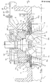
- Fig. 1 is a partial longitudinal sectional elevation of a ball valve of the invention. 0
- Fig. 1 shows a ball valve 1 comprising a valve body 2 defining a valve chamber 3 with inlet and outlet openings 4,5 respectively at opposite upstream and downstream ends 6,7 along its longitudinal axis X-X.
- a ball-shaped valve member 8 is mounted in the valve chamber 3 between two annular sealing means 9,10 around said openings 4,5 with a central through bore 11 concentric and of substantially equal internal diameter to, the openings 4,5.
- the valve member 8 has drivingly connected thereto via a spigot 12 and socket 13 connection a valve stem 14.
- each said sealing means 9,10 comprises a ring-shaped seal support 15 having in one end 16 an annular slot 17 for housing one end 18 of an annular sealing element 19 whose other end 20 is radially inwardly bevelled to provide an inclined, preferably part spheroidal, sealing surface 21 for engagement with the part-spheroidal outer surface 22 of the valve member 8.
- the seal support 15 is slidably mounted in an annular recess 23 with a resilient biasing means in the form of helical springs 24 in engagement with its other end 25 so as to urge it axially against the valve member 8 in generally conventional manner.
- the seal support is, however, additionally provided with a radially outwardly extending flange 26 which is reciprocably displacable in an annular cylinder chamber 27 provided with hydraulic fluid connections 28,29 of a hydraulic fluid circuit 30 (indicated schematically) formed and arranged for applying driving force to each side of the flange 26 for controlling movement of the seal support 15 as with a double acting piston and cylinder arrangement.
- the hydraulic circuit 30 is arranged to operate at a working pressure of 5000 p.s.i. so as to provide sufficient driving force to overcome the line pressure exerted on the seal support.
- valve In Fig.l the valve is essentially shown in its closed position with the valve member 8 orientated to close the inlet and outlet openings 4,5 with its outer surface 22, these openings being firmly sealed by the sealing elements 19 as shown in the left hand, down-stream, side of the drawing where the seal support 9 is shown in its sealing position.
- the hydraulic circuit 30 In order to open the valve, the hydraulic circuit 30 is activated to drive the seal support 9 back against the line pressure exerted on its other end 25 and the spring 24, to its retracted position as shown in the right-hand part of the drawing.
- both seals would be operated synchronously and the illustration of the two different positions at the same time is simply for purposes of illustration and explanation.
- valve member can be easily rotated, no longer being subject to any friction from the sealing means, via the valve stem 14 thereby reducing the operational and performance demands on the valve control system.
- the sealing elements can be brought back into sealing engagement with the valve member around the through bore ends to provide a continuous sealed passage right through the valve.
- sealing element 19 Since the sealing element 19 is no longer subject to any significant frictional or other transverse or torsional forces, the design criteria relating thereto in particular the choice of suitable materials are considerably relaxed.
- the sealing elements may be made of plastics materials, natural or synthetic rubber, or even metal.
- valve stem seals 31 With the reduced stresses imposed on the sealing means it will be appreciated that the working life thereof will be substantially increased and the need for maintenance thereof considerably reduced. Thus the main service requirement becomes the maintenance and replacement of the valve stem seals 31. This can now be readily achieved though without necessarily shutting down the pipeline by the use of a back seat seal 32 on a radially outer flange surface 33 of the valve stem 14 which engages with an inner canopy 34 immediately any line pressure is applied to the radially inner flange surface 35. This provides an important safeguard to maintenance personnel involved in removing the outer canopy 36 to provide access to the valve stem seals 31.
- valve stem 14 Since such movement of the valve stem 14 tends to lead to a partial disengagement of the spigot and socket connection 12,13 with the valve member, re-engagement (after relief of the line pressure from below the valve stem) can present difficulties in conventional designs due to movement of the valve member. With the present design though these can be substantially avoided by virtue of the very accurate precise positioning of the valve member via its sealing means which can be achieved.
- the hydraulic circuit 30 includes a reservoir 31, a pump 32 e.g. a hand pump for use in pressurizing the circuit via a non-return valve when ball-valve operation is required, a pressure accumulator 33, a change-over valve 34 and a safety valve 35.
- a pump 32 e.g. a hand pump for use in pressurizing the circuit via a non-return valve when ball-valve operation is required
- a pressure accumulator 33 e.g. a hand pump for use in pressurizing the circuit via a non-return valve when ball-valve operation is required
- a pressure accumulator 33 e.g. a pressure accumulator
- a change-over valve 34 e.g. a change-over valve
Landscapes
- Engineering & Computer Science (AREA)
- General Engineering & Computer Science (AREA)
- Mechanical Engineering (AREA)
- Taps Or Cocks (AREA)
- External Artificial Organs (AREA)
- Multiple-Way Valves (AREA)
Abstract
Description
- The present invention relates to a ball valve and in particular to ball valves suitable for use in oil and gas well pipelines and in petrochemical plant.
- Ball valves are relatively widely used in oil-well pipelines but due to the relatively high operating pressures involved and more particularly the relatively heterogeneous nature of crude oil recovered from most oil-wells the oil often containing significant amounts of particulate matter the relatively soft seals used for sealing between the valve openings and the ball shaped valve member are subject to frequent damage resulting in significant down-time and costly maintenance involving substantial dismantling of the valve.
- It is an object of the present invention to avoid or minimize one or more of the above disadvantages.
- The present invention provides a ball valve comprising a valve body having a valve chamber with first and second openings at respective ends along a longitudinal axis of the valve, and a ball-shaped valve member with a radially extending valve stem adapted for rotation of said valve member about an axis extending transversely of said longitudinal axis, said valve member having a spheroidal outer surface interrupted by a generally central through-bore extending transversely of the valve stem axis for movement into and out of communication with said first and second openings as said valve member is rotated about the valve stem axis, each of said first and second openings being provided with an annular sealing means formed and arranged for sealing engagement with the valve member outer surface in a closed position of the valve wherein at least said sealing means on an upstream side of the valve is in the form of an annular sealing element mounted in an annular seal support mounted in said valve body so as to be reciprocably displacable along the longitudinal valve axis between a sealing position in which said sealing element is held in sealing engagement with said valve member outer surface and a retracted position, in which said sealing element is held spaced from said outer surface, a seal support-drive means is formed and arranged for applying a driving force to said seal support, at least in the upstream direction for retraction of said seal support towards its retracted position.
- With a ball valve of the present invention the possibility of damage to the valve seals is substantially reduced leading to a corresponding increase in effective life and decrease in down time. Moreover opening and closing of the valve is made much easier with the result that the valve control means can be significantly downrated resulting in further important economies of construction.
- Conveniently the drive means comprises a piston means connected to the seal support and reciprocably displacable in a chamber connected to a pressurized fluid supply. Most conveniently the piston and chamber means is formed and arranged to operate as a double action piston. Desirably the downstream side sealing means also is of similar form to the upstream side sealing means.
- With the latter type of arrangement it will be appreciated that a balanced driving force can be applied to each side of the valve member so that it is accurately positioned with respect to the valve stem. This in turn has the further advantage of facilitating the use of a back seat sealing means on the valve stem to act as a safeguard against leakage of pressurized oil or other fluid upon removal of the valve stem access canopy when the valve has been accidentally left part open. In such cases the valve stem is forced upwards away from the valve member into a sealing position, correct subsequent re-engagement of the valve stem with the valve member being ensured by the accurate positioning of the valve member as will be further explained hereinbelow.
- Further preferred features and advantages of the invention will appear from the following detailed description given by way of example of a preferred embodiment illustrated with reference to the accompanying drawing in which:
- Fig. 1 is a partial longitudinal sectional elevation of a ball valve of the invention. 0
- Fig. 1 shows a ball valve 1 comprising a valve body 2 defining a
valve chamber 3 with inlet andoutlet openings 4,5 respectively at opposite upstream anddownstream ends 6,7 along its longitudinal axis X-X. A ball-shaped valve member 8 is mounted in thevalve chamber 3 between two annular sealing means 9,10 around saidopenings 4,5 with a central through bore 11 concentric and of substantially equal internal diameter to, theopenings 4,5. Thevalve member 8 has drivingly connected thereto via aspigot 12 andsocket 13 connection avalve stem 14. - In more detail each said sealing means 9,10 comprises a ring-
shaped seal support 15 having in oneend 16 anannular slot 17 for housing oneend 18 of anannular sealing element 19 whose other end 20 is radially inwardly bevelled to provide an inclined, preferably part spheroidal, sealingsurface 21 for engagement with the part-spheroidalouter surface 22 of thevalve member 8. Theseal support 15 is slidably mounted in anannular recess 23 with a resilient biasing means in the form ofhelical springs 24 in engagement with itsother end 25 so as to urge it axially against thevalve member 8 in generally conventional manner. - The seal support is, however, additionally provided with a radially outwardly extending
flange 26 which is reciprocably displacable in anannular cylinder chamber 27 provided withhydraulic fluid connections 28,29 of a hydraulic fluid circuit 30 (indicated schematically) formed and arranged for applying driving force to each side of theflange 26 for controlling movement of theseal support 15 as with a double acting piston and cylinder arrangement. Thehydraulic circuit 30 is arranged to operate at a working pressure of 5000 p.s.i. so as to provide sufficient driving force to overcome the line pressure exerted on the seal support. - In Fig.l the valve is essentially shown in its closed position with the
valve member 8 orientated to close the inlet andoutlet openings 4,5 with itsouter surface 22, these openings being firmly sealed by thesealing elements 19 as shown in the left hand, down-stream, side of the drawing where theseal support 9 is shown in its sealing position. In order to open the valve, thehydraulic circuit 30 is activated to drive theseal support 9 back against the line pressure exerted on itsother end 25 and thespring 24, to its retracted position as shown in the right-hand part of the drawing. Naturally in practice both seals would be operated synchronously and the illustration of the two different positions at the same time is simply for purposes of illustration and explanation. Once the seals have been retracted the valve member can be easily rotated, no longer being subject to any friction from the sealing means, via thevalve stem 14 thereby reducing the operational and performance demands on the valve control system. When the valve member has been rotated until its through bore is aligned with the openings i.e. the valve is in its open position, the sealing elements can be brought back into sealing engagement with the valve member around the through bore ends to provide a continuous sealed passage right through the valve. - Since the sealing
element 19 is no longer subject to any significant frictional or other transverse or torsional forces, the design criteria relating thereto in particular the choice of suitable materials are considerably relaxed. Thus the sealing elements may be made of plastics materials, natural or synthetic rubber, or even metal. - With the reduced stresses imposed on the sealing means it will be appreciated that the working life thereof will be substantially increased and the need for maintenance thereof considerably reduced. Thus the main service requirement becomes the maintenance and replacement of the
valve stem seals 31. This can now be readily achieved though without necessarily shutting down the pipeline by the use of aback seat seal 32 on a radiallyouter flange surface 33 of thevalve stem 14 which engages with aninner canopy 34 immediately any line pressure is applied to the radiallyinner flange surface 35. This provides an important safeguard to maintenance personnel involved in removing theouter canopy 36 to provide access to thevalve stem seals 31. Since such movement of thevalve stem 14 tends to lead to a partial disengagement of the spigot andsocket connection - The
hydraulic circuit 30 includes areservoir 31, apump 32 e.g. a hand pump for use in pressurizing the circuit via a non-return valve when ball-valve operation is required, apressure accumulator 33, a change-overvalve 34 and asafety valve 35. For simplicity the drawing shows the circuit to only one of the valve seal drive means but where both valve seals are in accordance with the present invention, the circuit would be connected to both so that both valve seals would operate in parallel with each other.
Claims (8)
Applications Claiming Priority (2)
| Application Number | Priority Date | Filing Date | Title |
|---|---|---|---|
| GB8409226 | 1984-04-10 | ||
| GB8409226 | 1984-04-10 |
Publications (2)
| Publication Number | Publication Date |
|---|---|
| EP0161056A2 true EP0161056A2 (en) | 1985-11-13 |
| EP0161056A3 EP0161056A3 (en) | 1988-03-16 |
Family
ID=10559458
Family Applications (1)
| Application Number | Title | Priority Date | Filing Date |
|---|---|---|---|
| EP85302253A Withdrawn EP0161056A3 (en) | 1984-04-10 | 1985-04-01 | Ball valve |
Country Status (3)
| Country | Link |
|---|---|
| EP (1) | EP0161056A3 (en) |
| JP (1) | JPS60260774A (en) |
| NO (1) | NO159681C (en) |
Cited By (8)
| Publication number | Priority date | Publication date | Assignee | Title |
|---|---|---|---|---|
| WO1991018229A1 (en) * | 1990-05-16 | 1991-11-28 | Aarnes Raag | Arrangement in closing valves |
| EP0690253A1 (en) * | 1994-07-01 | 1996-01-03 | BORSIG KUGELHAHN GmbH | Obturator sealing device |
| EP1258662A3 (en) * | 2001-05-17 | 2003-12-10 | Weinhold, Karl Dipl.-Ing. (FH) | Device for shutting off a fluid flow in a pipeline by a a ball-shaped shut-off member |
| EP2487392A3 (en) * | 2011-02-11 | 2013-10-23 | Yeary & Associates, Inc. | Differential pressure sealing device for ball valves |
| WO2014161207A1 (en) * | 2013-04-04 | 2014-10-09 | Qiu Jinquan | New high-pressure micro-torque ball valve |
| ITMI20132031A1 (en) * | 2013-12-05 | 2015-06-06 | Ast Internat S R L | VALVE ASSEMBLY |
| WO2018083278A1 (en) * | 2016-11-04 | 2018-05-11 | Franz Schuck Gmbh | Ball valve for a pipe system for conveying liquid or gaseous media |
| CN108343757A (en) * | 2018-04-03 | 2018-07-31 | 浙江精嘉阀门有限公司 | Hydraulic control band bypasses linkage ball valve |
Families Citing this family (8)
| Publication number | Priority date | Publication date | Assignee | Title |
|---|---|---|---|---|
| JPH01109666U (en) * | 1988-01-18 | 1989-07-25 | ||
| WO1991019921A1 (en) * | 1990-06-20 | 1991-12-26 | Den Norske Stats Oljeselskap A/S | Valve arrangement, in particular a large ball valve |
| KR100782900B1 (en) | 2005-05-13 | 2007-12-06 | 이성수 | Ball valve and valve open-close system with it |
| DE202008011406U1 (en) * | 2007-12-20 | 2009-06-18 | Xomox International Gmbh & Co | Valve |
| CN102425678B (en) * | 2011-12-05 | 2014-05-14 | 广东明珠流体机械有限公司 | Mobile sealed valve |
| CN105065706B (en) * | 2015-08-07 | 2018-05-29 | 张鹤鸣 | Air sac sealing type stainless steel semisphere valve |
| BR112019019979A2 (en) | 2017-03-31 | 2020-04-28 | Ant Applied New Tech Ag | aqueous abrasive suspension cutting installation |
| CN113685574A (en) * | 2021-09-03 | 2021-11-23 | 浙江力诺流体控制科技股份有限公司 | Ball valve of external air source control valve seat |
Citations (4)
| Publication number | Priority date | Publication date | Assignee | Title |
|---|---|---|---|---|
| FR2094215A5 (en) * | 1970-05-22 | 1972-02-04 | Tarn Ste Nouvelle Saut | |
| US3749357A (en) * | 1972-04-07 | 1973-07-31 | Acf Ind Inc | Valve structure having fluid pressure actuated seats |
| DE2527573A1 (en) * | 1975-06-20 | 1977-02-03 | Taimei Kinzoku Kogyo K K | Rotary hydraulic valve with pressure loaded seal - is unloaded when dog clutch actuator moves to open valve to minimise required turning moment |
| DE2938265A1 (en) * | 1979-09-21 | 1981-04-16 | M.A.N. Maschinenfabrik Augsburg-Nürnberg AG, 8500 Nürnberg | Pipe line coupling with controlled seal pressure - has triple piston with floating seal |
-
1985
- 1985-04-01 EP EP85302253A patent/EP0161056A3/en not_active Withdrawn
- 1985-04-09 NO NO851404A patent/NO159681C/en unknown
- 1985-04-10 JP JP7633185A patent/JPS60260774A/en active Pending
Patent Citations (4)
| Publication number | Priority date | Publication date | Assignee | Title |
|---|---|---|---|---|
| FR2094215A5 (en) * | 1970-05-22 | 1972-02-04 | Tarn Ste Nouvelle Saut | |
| US3749357A (en) * | 1972-04-07 | 1973-07-31 | Acf Ind Inc | Valve structure having fluid pressure actuated seats |
| DE2527573A1 (en) * | 1975-06-20 | 1977-02-03 | Taimei Kinzoku Kogyo K K | Rotary hydraulic valve with pressure loaded seal - is unloaded when dog clutch actuator moves to open valve to minimise required turning moment |
| DE2938265A1 (en) * | 1979-09-21 | 1981-04-16 | M.A.N. Maschinenfabrik Augsburg-Nürnberg AG, 8500 Nürnberg | Pipe line coupling with controlled seal pressure - has triple piston with floating seal |
Cited By (12)
| Publication number | Priority date | Publication date | Assignee | Title |
|---|---|---|---|---|
| WO1991018229A1 (en) * | 1990-05-16 | 1991-11-28 | Aarnes Raag | Arrangement in closing valves |
| US5322261A (en) * | 1990-05-16 | 1994-06-21 | Rag Aarnes | Arrangement in closing valves |
| EP0690253A1 (en) * | 1994-07-01 | 1996-01-03 | BORSIG KUGELHAHN GmbH | Obturator sealing device |
| EP1258662A3 (en) * | 2001-05-17 | 2003-12-10 | Weinhold, Karl Dipl.-Ing. (FH) | Device for shutting off a fluid flow in a pipeline by a a ball-shaped shut-off member |
| EP2487392A3 (en) * | 2011-02-11 | 2013-10-23 | Yeary & Associates, Inc. | Differential pressure sealing device for ball valves |
| WO2014161207A1 (en) * | 2013-04-04 | 2014-10-09 | Qiu Jinquan | New high-pressure micro-torque ball valve |
| ITMI20132031A1 (en) * | 2013-12-05 | 2015-06-06 | Ast Internat S R L | VALVE ASSEMBLY |
| WO2018083278A1 (en) * | 2016-11-04 | 2018-05-11 | Franz Schuck Gmbh | Ball valve for a pipe system for conveying liquid or gaseous media |
| EP3754236A1 (en) * | 2016-11-04 | 2020-12-23 | Franz Schuck GmbH | Processes for a ball valve for a conduit system for conveying liquid or gaseous media |
| US11079034B2 (en) | 2016-11-04 | 2021-08-03 | Franz Schuck Gmbh | Ball valve for a pipe system for conveying liquid or gaseous media |
| CN108343757A (en) * | 2018-04-03 | 2018-07-31 | 浙江精嘉阀门有限公司 | Hydraulic control band bypasses linkage ball valve |
| CN108343757B (en) * | 2018-04-03 | 2023-09-12 | 浙江精嘉阀门有限公司 | Hydraulic control by-pass linkage ball valve |
Also Published As
| Publication number | Publication date |
|---|---|
| EP0161056A3 (en) | 1988-03-16 |
| JPS60260774A (en) | 1985-12-23 |
| NO851404L (en) | 1985-10-11 |
| NO159681C (en) | 1989-01-25 |
| NO159681B (en) | 1988-10-17 |
Similar Documents
| Publication | Publication Date | Title |
|---|---|---|
| EP0161056A2 (en) | Ball valve | |
| US4850392A (en) | Double poppet relief valve | |
| US5494256A (en) | Dual seal ball valve | |
| US4568058A (en) | Dual stage hydraulic actuator for expanding gate valve | |
| EP0244185B1 (en) | Bellows valve | |
| US4634099A (en) | High pressure inverted bellows valve | |
| US6698712B2 (en) | Ball valve assembly | |
| US6227240B1 (en) | Unitized spherical profile check valve with replaceable sealing element | |
| CA1294599C (en) | Modular hydraulic actuator | |
| US4921000A (en) | Break-away coupling for hoselines | |
| US4436279A (en) | Stem connection for gate valve | |
| US4527630A (en) | Hydraulic actuating means for subsurface safety valve | |
| US5727775A (en) | Gate valve with dual seal rings on a unitary seat ring | |
| US4535967A (en) | Expanding gate valve with fluid-powered actuator | |
| US5322261A (en) | Arrangement in closing valves | |
| US3763880A (en) | Gate valve structure | |
| US4272055A (en) | Single double backseat | |
| US2830620A (en) | Valve | |
| US4172470A (en) | Soft seat valve | |
| CN1013297B (en) | Hydraulic pressure opening check valve specially adapted for hydraulic support system | |
| US3857410A (en) | Switching valve | |
| US4669547A (en) | High temperature subsurface safety valve | |
| USRE32390E (en) | Hydraulic actuating means for subsurface safety valve | |
| GB2121090A (en) | Well safety valve | |
| US5904179A (en) | Inlet check valve |
Legal Events
| Date | Code | Title | Description |
|---|---|---|---|
| PUAI | Public reference made under article 153(3) epc to a published international application that has entered the european phase |
Free format text: ORIGINAL CODE: 0009012 |
|
| AK | Designated contracting states |
Designated state(s): DE FR GB IT SE |
|
| PUAL | Search report despatched |
Free format text: ORIGINAL CODE: 0009013 |
|
| AK | Designated contracting states |
Kind code of ref document: A3 Designated state(s): DE FR GB IT SE |
|
| 17P | Request for examination filed |
Effective date: 19880915 |
|
| 17Q | First examination report despatched |
Effective date: 19890511 |
|
| STAA | Information on the status of an ep patent application or granted ep patent |
Free format text: STATUS: THE APPLICATION IS DEEMED TO BE WITHDRAWN |
|
| 18D | Application deemed to be withdrawn |
Effective date: 19891101 |
|
| RIN1 | Information on inventor provided before grant (corrected) |
Inventor name: MCSORLEY, DAVID Inventor name: MACLEAN, MALCOLM ALEXANDER |