US484455A - Island - Google Patents
Island Download PDFInfo
- Publication number
- US484455A US484455A US484455DA US484455A US 484455 A US484455 A US 484455A US 484455D A US484455D A US 484455DA US 484455 A US484455 A US 484455A
- Authority
- US
- United States
- Prior art keywords
- bracket
- knee
- arbor
- cutter
- machine
- Prior art date
- Legal status (The legal status is an assumption and is not a legal conclusion. Google has not performed a legal analysis and makes no representation as to the accuracy of the status listed.)
- Expired - Lifetime
Links
- 210000003127 knee Anatomy 0.000 description 16
- 101100001671 Emericella variicolor andF gene Proteins 0.000 description 1
- 241000220010 Rhode Species 0.000 description 1
- 230000002452 interceptive effect Effects 0.000 description 1
- 238000003801 milling Methods 0.000 description 1
- 230000013707 sensory perception of sound Effects 0.000 description 1
Images

Classifications
-
- B—PERFORMING OPERATIONS; TRANSPORTING
- B23—MACHINE TOOLS; METAL-WORKING NOT OTHERWISE PROVIDED FOR
- B23Q—DETAILS, COMPONENTS, OR ACCESSORIES FOR MACHINE TOOLS, e.g. ARRANGEMENTS FOR COPYING OR CONTROLLING; MACHINE TOOLS IN GENERAL CHARACTERISED BY THE CONSTRUCTION OF PARTICULAR DETAILS OR COMPONENTS; COMBINATIONS OR ASSOCIATIONS OF METAL-WORKING MACHINES, NOT DIRECTED TO A PARTICULAR RESULT
- B23Q1/00—Members which are comprised in the general build-up of a form of machine, particularly relatively large fixed members
- B23Q1/70—Stationary or movable members for carrying working-spindles for attachment of tools or work
-
- Y—GENERAL TAGGING OF NEW TECHNOLOGICAL DEVELOPMENTS; GENERAL TAGGING OF CROSS-SECTIONAL TECHNOLOGIES SPANNING OVER SEVERAL SECTIONS OF THE IPC; TECHNICAL SUBJECTS COVERED BY FORMER USPC CROSS-REFERENCE ART COLLECTIONS [XRACs] AND DIGESTS
- Y10—TECHNICAL SUBJECTS COVERED BY FORMER USPC
- Y10T—TECHNICAL SUBJECTS COVERED BY FORMER US CLASSIFICATION
- Y10T409/00—Gear cutting, milling, or planing
- Y10T409/30—Milling
- Y10T409/309576—Machine frame
- Y10T409/309632—Overarm harness structure
Definitions
- My invention has for its object to provide a firm and steady support for the outer end of the cutter-arbor of a milling-machine; and to that end it consists in the combination and arrangement of parts hereinafter described.
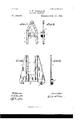
- Figure l is an end elevation
- Fig. 2 a side elevation, of a milling-machine embodying my invention.
- Figs. 3 to 6, inclusive, are detailed views, upon an enlarged scale, of certain of the parts.
- A represents the frame of a milling-machine With a driving-spindle, pulleys, and gearing mounted thereon, as usual.
- 13 represents the vertically-adj ustable knee, arranged to slide on ways upon the frame, the adjustment of which is eifected by the shaft a, operating the screw b in the usual manner.
- C represents the platen or work-carriage, arranged to slidein suitable ways upon the saddle C.
- c is the cutter-arbor, secured atone end to the driving-spindle and carrying the cutters c c D is a bar mounted in the frame and longitudinally adjustable therein.
- bracket E adj ustably secured to the knee B
- bracket F secured to the adjustable bar D.
- the bracket E which is provided with two arms 6 e, is secured in any adjusted position on the knee B by means of a gib e and clamp-screw e Serial No. 424,964. (No model.)
- the bracket F is likewise provided with two arms ff, and in a cross-bar f'of said bracket F is formed a bearing f for the outer end of the cutter-arbor.
- a bearing f for the outer end of the cutter-arbor.
- the brackets E andF are constructed to permit of such adjustment.
- the arms e e of the bracket E are provided with slots 8 as shown in Fig. 5, and the arms f f of the bracketF are likewise provided with corresponding slots f through which slots pass the clamp-bolts g, which clamp the two brackets together.
- the bracket E may be likewise raised or lowered with the knee and with relation to the bracket F without affecting the position of the bearing f which is in the bracket F, secured to the bar D.
- the cutter-arbor will be at all times firmly supported in all directions, but without interfering in any Way with the adjustment of the knee.
- the arm d may be arranged between the two cutters, the bearing f serving to furnish a firm and steady support for the outer end of the arbor.
- the bar D is not adjustable in the frame.
- bracket E will not require to be adjustable upon-the knee of the machine.
- the slots f in the bracket F may be omitted, said bracket being instead provided simply with holes for the reception of the clamp-bolts, and the slots e in the bracket E made continuous, which arrangement Will likewise serve to permit of the vertical adjustment of the knee without by said cutter-arbor will be. firmly supported I in all directions, substantially as described.
Landscapes
- Engineering & Computer Science (AREA)
- Mechanical Engineering (AREA)
- Milling Processes (AREA)
Description
(No Model.) 2 Sheets-Sheet 1.
G. H. PHILLIPS; MILLING MACHINE.
No. 484,455. Patented Oct. 18, 1892.
(No Model.) 2 SheetsSheet 2 O. H. PHILLIPS. MILLING MACHINE.
No. 484,455. Patentd 0'04. 18, 1892.
UNITED STATES PATENT OFFICE.
CHARLES H. PHILLIPS, OF PROVIDENCE, RHODE'ISLAND, ASSIGNOR TO THE BROWN & SHARPE MANUFACTURING COMPANY, OF SAME PLACE.
MILLING-MACHINE.
SPECIFICATION formingpart of Letters Patent No. 484.455, dated October 18, 1892.
Application filed March l5, 18 92.
To all whom it may concern:
Be it known that 1, CHARLES H. PHILLIPS, of the city and county of Providence, in the State of Rhode Island, have invented certain new and useful Improvementsin Milling-Machines; and I do hereby declare the following specification, taken in connection with the accompanying drawings, forming a part of the same, to be a full, clear, and exact description thereof.
My invention has for its object to provide a firm and steady support for the outer end of the cutter-arbor of a milling-machine; and to that end it consists in the combination and arrangement of parts hereinafter described.
Referring to the drawings, Figure l is an end elevation, and Fig. 2 a side elevation, of a milling-machine embodying my invention. Figs. 3 to 6, inclusive, are detailed views, upon an enlarged scale, of certain of the parts.
A represents the frame of a milling-machine With a driving-spindle, pulleys, and gearing mounted thereon, as usual.
13 represents the vertically-adj ustable knee, arranged to slide on ways upon the frame, the adjustment of which is eifected by the shaft a, operating the screw b in the usual manner.
C represents the platen or work-carriage, arranged to slidein suitable ways upon the saddle C.
cis the cutter-arbor, secured atone end to the driving-spindle and carrying the cutters c c D is a bar mounted in the frame and longitudinally adjustable therein.
It has been customary heretofore to employ an arm or bracket, as d, adj ustably mounted on the bar D for supporting the outer end of the cutter-arbor. Such arm or bracket, however, has been found not to furnish a sufficiently firm and steady support for the cutter-arbor, especially in alateral direction, under all conditions.
In order to secure the necessary firm and steady support for the cutter-arbor in all directions, I employ a bracket E, adj ustably secured to the knee B, and a second bracket F, secured to the adjustable bar D. The bracket E, which is provided with two arms 6 e, is secured in any adjusted position on the knee B by means of a gib e and clamp-screw e Serial No. 424,964. (No model.)
The bracket F is likewise provided with two arms ff, and in a cross-bar f'of said bracket F is formed a bearing f for the outer end of the cutter-arbor. By bolting firmly together the arms of the brackets E and F the cutterarbor c, with its end supported in the bearing f will be given a firm and steady supportin all directions, laterally as well as from both above and below. As the bar D is longitudinally adjustable in its bearings, and as the bracket E is likewise adjustable upon the knee B, the bearing f may be adjusted to accommodate arbors of different lengths.
To provide for the vertical adjustment of the knee B, the brackets E andF are constructed to permit of such adjustment. For this purpose the arms e e of the bracket E are provided with slots 8 as shown in Fig. 5, and the arms f f of the bracketF are likewise provided with corresponding slots f through which slots pass the clamp-bolts g, which clamp the two brackets together. With this arrangement when the knee B is to be raised or lowered by unclamping the bolts 9 the bracket E may be likewise raised or lowered with the knee and with relation to the bracket F without affecting the position of the bearing f which is in the bracket F, secured to the bar D. Thus the cutter-arbor will be at all times firmly supported in all directions, but without interfering in any Way with the adjustment of the knee. With the combination and arrangement above described two cutters may be employed simultaneously, as shown in Fig. 2, in which case the arm d may be arranged between the two cutters, the bearing f serving to furnish a firm and steady support for the outer end of the arbor.
In some forms of milling-machines the bar D is not adjustable in the frame.
It is plain that the invention hereinbefore set forth may be likewise applied to a machine of that character, in which case the bracket E will not require to be adjustable upon-the knee of the machine. If desired, the slots f in the bracket F may be omitted, said bracket being instead provided simply with holes for the reception of the clamp-bolts, and the slots e in the bracket E made continuous, which arrangement Will likewise serve to permit of the vertical adjustment of the knee without by said cutter-arbor will be. firmly supported I in all directions, substantially as described.
2. The combination, with the knee of a milling-machine, of a bracketadjustably secured to said knee, a bar adjustably mounted in hearings in the frame of the machine, and a bracket secured to said bar, said last-named bracket being provided with a bearing for the 20 outer end of the cutter-arbor and said two brackets being clamped together, whereby said cutter-arbor will be firmly supported in all directions, substantially as described.
3. The combination, with the knee ofa milling-machine, said knee being vertically adj ustable, of a bracket secured to said knee, a bar mounted in bearings in the frame of said machine, and a bracket secured to said bar, said last-named bracket being provided with a bearing for the outer end of the cutter-arbor and one or both of said brackets being provided with slots for the clamp-b0lts,whereby said knee with the bracket secured thereto may be adjusted vertically with relation to the other bracket and the bearing therein, substantially as described.
CHARLES H. PHILLIPS. Witnesses:
W. H. THURSTON, S. J. MURPHY.
Publications (1)
| Publication Number | Publication Date |
|---|---|
| US484455A true US484455A (en) | 1892-10-18 |
Family
ID=2553304
Family Applications (1)
| Application Number | Title | Priority Date | Filing Date |
|---|---|---|---|
| US484455D Expired - Lifetime US484455A (en) | Island |
Country Status (1)
| Country | Link |
|---|---|
| US (1) | US484455A (en) |
-
0
- US US484455D patent/US484455A/en not_active Expired - Lifetime
Similar Documents
| Publication | Publication Date | Title |
|---|---|---|
| US484455A (en) | Island | |
| US292927A (en) | Index head foe milling machines | |
| US333631A (en) | Universal head for milling-machin es | |
| US1180842A (en) | Strip-sawing machine. | |
| US650644A (en) | Machine-vise. | |
| US429880A (en) | Steady-rest for lathes | |
| US361105A (en) | Drill-press | |
| US491521A (en) | Island | |
| US696309A (en) | Multiple gage for lathe work. | |
| US497524A (en) | loteall | |
| US911639A (en) | Boring-machine. | |
| US1053296A (en) | Milling-machine. | |
| US111311A (en) | Improvement in head-stocks for milling-machines | |
| US593491A (en) | Horizontal drilling and boring machine | |
| US176568A (en) | Improvement in watchmakers lathes | |
| US578588A (en) | Milling-machine | |
| US414174A (en) | Work-holder for milling-machines | |
| US787690A (en) | Lathe. | |
| US509444A (en) | Machine | |
| US189812A (en) | Improvement in molding-machines | |
| US696951A (en) | Routing or engraving machine. | |
| US432529A (en) | James hollingworth | |
| US995420A (en) | Counterbalancing device for machine-tools. | |
| US170591A (en) | Improvement in metal-drilling machines | |
| US1058720A (en) | Cross-rail-securing device for machine-tools. |