US4836697A - Automated thermal transfer device and control system therefor - Google Patents
Automated thermal transfer device and control system therefor Download PDFInfo
- Publication number
- US4836697A US4836697A US07/170,796 US17079688A US4836697A US 4836697 A US4836697 A US 4836697A US 17079688 A US17079688 A US 17079688A US 4836697 A US4836697 A US 4836697A
- Authority
- US
- United States
- Prior art keywords
- tape
- ribbon
- printhead
- pixel data
- rotational speed
- Prior art date
- Legal status (The legal status is an assumption and is not a legal conclusion. Google has not performed a legal analysis and makes no representation as to the accuracy of the status listed.)
- Expired - Fee Related
Links
Images


Classifications
-
- G—PHYSICS
- G06—COMPUTING; CALCULATING OR COUNTING
- G06K—GRAPHICAL DATA READING; PRESENTATION OF DATA; RECORD CARRIERS; HANDLING RECORD CARRIERS
- G06K15/00—Arrangements for producing a permanent visual presentation of the output data, e.g. computer output printers
- G06K15/02—Arrangements for producing a permanent visual presentation of the output data, e.g. computer output printers using printers
- G06K15/12—Arrangements for producing a permanent visual presentation of the output data, e.g. computer output printers using printers by photographic printing, e.g. by laser printers
- G06K15/1295—Arrangements for producing a permanent visual presentation of the output data, e.g. computer output printers using printers by photographic printing, e.g. by laser printers using a particular photoreceptive medium
-
- B—PERFORMING OPERATIONS; TRANSPORTING
- B41—PRINTING; LINING MACHINES; TYPEWRITERS; STAMPS
- B41J—TYPEWRITERS; SELECTIVE PRINTING MECHANISMS, i.e. MECHANISMS PRINTING OTHERWISE THAN FROM A FORME; CORRECTION OF TYPOGRAPHICAL ERRORS
- B41J2/00—Typewriters or selective printing mechanisms characterised by the printing or marking process for which they are designed
- B41J2/315—Typewriters or selective printing mechanisms characterised by the printing or marking process for which they are designed characterised by selective application of heat to a heat sensitive printing or impression-transfer material
- B41J2/32—Typewriters or selective printing mechanisms characterised by the printing or marking process for which they are designed characterised by selective application of heat to a heat sensitive printing or impression-transfer material using thermal heads
- B41J2/325—Typewriters or selective printing mechanisms characterised by the printing or marking process for which they are designed characterised by selective application of heat to a heat sensitive printing or impression-transfer material using thermal heads by selective transfer of ink from ink carrier, e.g. from ink ribbon or sheet
-
- B—PERFORMING OPERATIONS; TRANSPORTING
- B41—PRINTING; LINING MACHINES; TYPEWRITERS; STAMPS
- B41J—TYPEWRITERS; SELECTIVE PRINTING MECHANISMS, i.e. MECHANISMS PRINTING OTHERWISE THAN FROM A FORME; CORRECTION OF TYPOGRAPHICAL ERRORS
- B41J2/00—Typewriters or selective printing mechanisms characterised by the printing or marking process for which they are designed
- B41J2/52—Arrangement for printing a discrete number of tones, not covered by group B41J2/205, e.g. applicable to two or more kinds of printing or marking process
Definitions
- the present invention relates generally to the field of printing apparatus or composing systems, and more particularly, to an improved control means for a printing apparatus or composing system of the type involving the use of a thermal process to transfer pixel images of a desired character or design from a color carrying ribbon onto an image carrying tape as a result of the localized application heat and pressure at each pixel.
- This type of printing apparatus or composing system has particular application in the printing of relatively large characters or sequences of characters of varying type sizes and fonts for us in preparing lettering for engineering drawings, flip charts, overhead, transparencies, posters, advertising brochures, identification labels and the like.
- the characters printed by this type of printing apparatus or system are generally larger than characters produced by most typewriters or the like and include a wide variety of type sizes and fonts for alphanumeric characters, along with any number of special characters or images such as symbols, logos and trademarks.
- Thermal transfer printing devices also exist in which an image of a desired character is formed on a strip of image carrying tape by transferring ink or other color from a color carrying ribbon to the tape as a result of the localized application of heat and a small amount of pressure.
- a typical thermal transfer device of this type is described in U.S. Pat. No. 4,666,319.
- Another thermal transfer device presently available employs a thermal print head for transferring images from a strip of ribbon to a strip of tape and has a cooperating tape-ribbon cartridge for providing a supply of tape and ribbon to the device. While such devices are useful for printing smaller point size characters represented in a dot-matrix array font format, the control systems required by such devices are incapable of handling the precision and accuracy required for the high speed generation of high quality characters, particularly characters of larger point sizes.
- a platen roller located directly opposite the printhead is used to frictionally engage the tape and ribbon and advance the same past the printhead.
- This arrangement is undesirable in that the pressure necessary to insure that the tape and ribbon will be frictionally advanced by the platen roller is greater than the optimum pressure necessary to achieve a high quality thermal transfer.
- a ribbon take-up spool or spindle is used to simply pull the tape and ribbon past the printhead. This arrangement is also undesirable, however, in that the driving force is applied only to the ribbon and misalignment between the ribbon and tape may occur.
- any variations in the speed of the platen drive roller or the ribbon take-up spindle negatively impact the quality of print by smearing or smudging the pixel images at a given vertical segment of the tape or by causing a gap between adjacent or corresponding columns of print.
- this smearing or smudging of pixels is desirable in many printers where the transfer ink will melt or smear together to create a consistent and uniform image, it is undesirable in a high quality, high speed tape printing apparatus of the type contemplated by the present invention.
- the ribbon used in high quality thermal transfer tape printing apparatus is usually some type of plastic based ribbon, the pixel images transferred from the ribbon to the tape are uniformly defined and do not smear or smudge into one another. Therefore, precise alignment between vertical columns of print is necessary to achieve high quality, high speed lettering results when using a thermal transfer tape printing apparatus of the type contemplated by the present invention.
- a thermal transfer device and in particular a control system for such a device, is provided in which an image of a desired character is transferred from a strip of color carrying ribbon to a strip of image carrying tape.
- a device includes an image transfer station defined by a printhead and a cylindrical platen and rotary drive means for advancing the tape and ribbon from a supply cartridge past the image transfer station. It may also include a tape-ribbon cartridge embodying an internal tape-cut mechanism and an input module for entering, editing, storing and transmitting the selected characters or designs to be printed on the tape.
- the control system of the present invention controls the mechanisms for transferring an image of a selected character or design from a ribbon to a tape.
- the control system is comprised of a programmable data processing means for receiving print data and control codes representing the desired characters or designs to be printed and for controlling the printing of that information by the image transfer station.
- the data processing means is also connected to a detector means for monitoring the speed and position of the rotary drive means.
- the speed of the rotary drive means as determined by the detector means is used by a feedback means to control the speed at which the rotary drive means advances the tape and ribbon past the image transfer station.
- the speed of the rotary drive means as determined by the detector means is also utilized to calculate position information of the tape and ribbon relative to the image transfer station. This position information is used by the data processing means to control the time at which print data is output to the printhead to insure that a precise alignment between corresponding vertical columns of print data is achieved.
- a primary object of the present invention is to provide an improved control system for a thermal transfer tape lettering device for transferring characters of a wide variety of type sizes and fonts from a strip of ribbon to a strip of image carrying tape.
- Another object of the present invention is to provide an improved control system for an image transfer station that will monitor and control the speed at which the tape and ribbon are advanced past the image transfer station and output the data to be printed by the image transfer station in relation to the position of the tape and ribbon as they are advanced past the image transfer station for the purpose of insuring a more accurate alignment between corresponding vertical columns of print data.
- Another object of the present invention is to provide an improved control system for a thermal transfer strip printer which monitors and controls the rotational speed of a rotary drive means and controls the position at which the image is transferred to the tape.
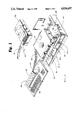
- FIG. 1 is an exploded pictorial view of a tape lettering printing apparatus in acccordance with the present invention showing a thermal transfer device with associated tape-ribbon cartridge, and an input module with an umbilical cord attachment to the thermal transfer device.
- FIG. 2 is a functional diagram of the control system for the thermal transfer device of the present invention showing various operative components of such system.
- FIG. 3 is a block diagram showing the data flow for processing means of the present invention.
- FIG. 4 is a simplified circuit diagram for the feedback means of the present invention.
- FIG. 5 is a pictorial view of the printhead assembly of the thermal transfer device.
- FIG. 6 is a functional schematic diagram of the input and output signals used to drive the printhead of the transfer device.
- FIG. 7 is a timing diagram of the input and output signals used to drive the printhead of the transfer device.
- FIG. 8 is a timing diagram of the overall data flow as controlled by the processing means fo the present invention.
- the operative components of the tape lettering or printing apparatus 10 gnerally include a thermal transfer device 12 embodying, a processing means 14, a pair of font cartridges 16 and 18, a rotary drive means 26 and an image transfer station 20 defined by and disposed between a printhead assembly 22 and a cooperating platen assembly 24.
- a thermal transfer device 12 embodying, a processing means 14, a pair of font cartridges 16 and 18, a rotary drive means 26 and an image transfer station 20 defined by and disposed between a printhead assembly 22 and a cooperating platen assembly 24.
- a movable cartridge service or receiving tray 28 for receiving a tape-ribbon cartridge 30.
- the cartridge 30 includes a supply of tape and ribbon for providing a tape 31 and a ribbon 32 to the image transfer station 20.
- the printing apparatus 10 further comprises an input means 40 for entering, editing, storing, manipulating, and/or transmitting input data to the processing means 14 via an umbilical cord interface 42.
- the input means 40 comprises a programmable digital microprocessor 44, a keyboard 46 and a display 48.
- the input means 40 may also, however, be a digital computer or other device capable of interfacing with the processing means 14 through the interface 42.
- the interface 42 is an RS-232-C communication port.
- control system has applicability to various lettering apparatus and strip printers, it has particular applicability to a thermal transfer device and associated tape-ribbon cartridge of the type shown and disclosed in co-pending applications entitled TAPE-RIBBON SUPPLY SYSTEM FOR A THERMAL TRANSFER DEVICE OR THE LIKE, Ser. No. 151,103, THERMAL TRANSFER DEVICE AND TAPE-RIBBON CARTRIDGE THEREFOR, Ser. No. 151,110, and THERMAL TRANSFER DEVICE AND TAPE-RIBBON CARTRIDGE EMBODYING A TAPE CUT-OFF MECHANISM, Ser. No. 151,109, all filed on Feb. 1, 1988 and all of which are incorporated by reference herein.
- the operative components of the thermal transfer device utilizing the control system of the present invention include a printhead assembly 22, a platen assembly 24 and a tape-ribbon drive means 26.
- the drive means 26 is a rotary drive means comprised of a drive motor 54 and an associated pair of drive roller 60 and 34 located downstream from the printhead and platen assemblies 22 and 24.
- the drive rollers 22 and 24 function to advance the tape 31 and ribbon 32 past the transfer station 20 defined by and positioned between the printhead and platen assemblies.
- the drive roller 60 is rotatably mounted within a drive roller housing 61 with top end of the drive roller shaft journaled in a portion of the housing 61.
- a drive gear 62 Adjacent to the lower end of the drive roller 60 is a drive gear 62 that is designed for meshing engagement with a corresponding drive gear 33 associated with the drive roller 34.
- the drive roller 34 is rotatably journaled in a housing portion 35.
- the roller 60 of the preferred embodiment is mounted in a portion of the machine housing 61, while the roller 34 is mounted in a portion of a tape-ribbon cartridge housing 35.
- the drive roller 34 is biased into engagement with the driver roller 60 by a pair of spring members (not shown) in the cartridge 30 (FIG. 1).
- a drive roller shaft 63 extends downwardly from the drive roller 60 and is connected at its lower end with a toothed gear 64.
- the toothed gear 64 is connected via an appropriate gear assembly 65 and a motor shaft 66 to the drive motor 54.
- the gear assembly 65 can comprise either a single gear as shown in the drawings or multiple gears.
- the drive motor 54 is a DC-servo motor, Model EN35-151N1B, available from Canon Precision of Tokyo, Japan.
- the motor 54 is a pulse driven motor or a servo motor driven with a pulse-width-modulated voltage pulse for high efficiency.
- an optical detection means or rotational optical encoder 70 for detecting the rotational speed of the shaft 66 so that the speed of the tape 31 and ribbon 32 and the position of the tape 31 and ribbon 32 relative to the printhead assembly 22 can be determined.
- the detection means 70 is implemented using a conventional rotational optical encoder or chopper wheel photo-detector having an optical interrupter 74 mounted on the motor shaft 66 and positioned between the motor 54 and the gear assembly 65.
- the optical interrupter is a plastic disc having a plurality of vanes 75.
- the interrupter 74 is coupled to the motor shaft 66 and is disposed between a light source and a photo-detector located in the detector housing 72. By detecting the presence or absence of light within the photo-detector 72, the detection means 70 translates the rotational speed of the shaft 66 into a digital pulse train or Processed Encoded Tick (V pet ) 76 having a frequency corresponding to the rotational speed of shaft 66.
- the platen assembly 24 includes a rotatable, cylindrically shaped platen 25 which is movable into an image transfer position relative to the printhead assembly 22. Movement of the platen 25 into such position is caused by the linear actuator 27 to create the desired printing pressure between the platen 25 and the printhead assembly 22.
- the structure illustrated in FIG. 2 also includes an electronic tape-ribbon sensor 230 positioned from the printhead assembly 22 and a tape cut-off mechanism 220 positioned downstream from the tape-ribbon drive means 26.
- an electronic tape-ribbon sensor 230 positioned from the printhead assembly 22
- a tape cut-off mechanism 220 positioned downstream from the tape-ribbon drive means 26.
- the printhead assembly 22 comprises a printhead 90 and an associated heat sink 91 mounted to a frame (not shown) for operative alignment with the platen assembly 24 (FIG. 2).
- the printhead assembly 22 is electrically connected to the processing means 14 (FIG. 1) via an appropriate electrical connector.
- the printhead 90 is a single column 300 dpi (dots per inch) thin film thermal printhead with associated integrated circuit drivers and which is identified as Model KFT-22-12MPE1-PA available from Kyocera International of Framingham, Mass.
- the printhead 90 consists of a single column of square heating elements 94, each heating element 94 representing a unique pixel and being electrically connected to a driver circuit 95.
- the driver circuit 95 electronically controls the head temperature of all of the heating elements 94.
- the printhead 90 of the preferred embodiment includes 256 heating elements 94 serially driven by four sixty-four bit driver chips illustrated by reference numerals 96, 97, 98 and 99.
- the driver circuit 95 receives data from the four driver chips (HIGH to print and LOW to not print) and applies a printing voltage to each of the heating elements 94 to thermally transfer the square area corresponding to that heating element from the thermal ribbon 32 to the image carrying tape 31.
- a thermal transfer ribbon 32 suitable for use with the preferred embodiment of this invention is Thermal Transfer Ribbon, Model TRX-6-5-4 available from Fuji Kagakusi of Kogyo, Japan.
- the image carrying tape 31 may be any type of plastic or polymer based film that is capable of receiving a thermal transfer of an image without distorting the substrate or carrier material.
- control system of the present invention includes a processing means (generally illustrated in FIG. 1 by the reference numeral 14 and more specifically illustrated in FIGS. 2 and 3 by the reference numerals 50 and 52) for receiving various input data and processing the same to generate data and control signals to drive the printhead assembly 22. More specifically, the processor 52 receives Input Data 100 representing selected characters or designs to be printed and Font Data 110 generally representing a set of character outlines. The processor 52 then processes the Input Data 100 and Font Data 110 to generate Output Data 130 and Control Signals 140, through a FIFO Buffer 134, to be provided to the output processor 50 in response to an Interrupt Signal 160.
- a processing means generally illustrated in FIG. 1 by the reference numeral 14 and more specifically illustrated in FIGS. 2 and 3 by the reference numerals 50 and 52
- the processor 52 receives Input Data 100 representing selected characters or designs to be printed and Font Data 110 generally representing a set of character outlines.
- the processor 52 then processes the Input Data 100 and Font Data 110 to generate Output Data 130 and Control Signals
- the output processor 50 receives the Output Data 130 and Control Signals 140 and provides the printhead assembly 22 with Print Data 150 in the form of a single columnar set of pixel data representing the selected characters to be printed.
- the processor 50 also supplies Control Signals 140 to the printhead assembly 22 to print the characters represented by Output Data 130.
- processors 50 and 52 are programmable digital microprocessors with the output processor 50 being an 8051 microprocessor available from Intel Corporation of Santa Clara, Calif. and the processor 52 being an 80186 rasterization microprocessor, also available from Intel Corporation.
- Control Signals 140 and Print Data 150 are generated by a real-time rasterization system based on Input Data 100 representing the desired characters to be printed and Font Data 110 representing the outlines for such characters, it will be apparent to those skilled in the art that Control Signals 140 and Print Data 150 may be supplied by any number of methods or in any number of formats without departing from the spirit of the present invention.
- Print Data 150 might be generated from a dot-matrix representation of the selected characters to be printed, instead of being based on an outline representation of the characters; or Print Data 150 might be simultaneously transmitted as multiple columns of pixel data, instead of sequentially transmitted as single columns of pixel data.
- Control Signals 140 might be separate control lines connected to the output processor 50, or they might be incorporated as special control codes contained within Print Data 150.
- the present invention overcomes the inadequacies of the prior art by both controlling the speed at which the tape 31 and ribbon 32 are transported past the image transfer station 20 and by controlling and monitoring the position of the tape 31 and ribbon 32 so that each column of pixels is printed at the appropriate and predefined position on the tape. This is accomplished by the combination of a detection means 70 and a feedback means 80 that are connected to the drive motor 54 and the output processor 50.
- the tape 31 and ribbon 32 are advanced past the image transfer station 20 by the drive rollers 60 and 34 at a constant rate (1 inch per second) and the vertical columns of pixel data are printed at a width of 300 pixels per inch.
- the detector 70 since the detector 70 is used for sensing both the proper location of the 300 pixels per inch and the proper drive speed, it must provide an integer multiple of 300 counts per inch, which also means 300 counts per second. Because of the operational characteristics of the drive motor 54, and to enable realization of the control circuitry described below, the desired detector 70 count rate was set at 1200 Hz. It is contemplated that software modification can be made to provide for different pixel width and frequency. It will be seen that various other types of detection means 70 would work equally well with the present invention.
- any rotational detector means which produces position and speed information and which is mounted on the drive motor shaft 66 would achieve the same results as the rotational encoder 70. It is also seen that the placement of detection means 70 on the drive motor shaft 66 is optional, and that the detection means 70 could also be mounted on the drive roller shaft 63 and utilize a different detector count rate. Even though the objective is to monitor the speed and location of the drive roller 60, and thus the tape 31 and ribbon 32, locating the detection means 70 on the drive motor shaft 66 accomplishes this objective because the rotary drive means 26 is only operated in a forward direction and the gear ratio of gear assembly 65 is fixed and known.
- detection means other than rotational speed detection means could be utilized.
- detection means to detect the linear speed or movement of the tape 31 or ribbon 32 could be used as long as the means is capable of generating the tape-ribbon position and speed data needed for use in the processors 50 and 52.
- FIG. 4 illustrating the feedback means 80 used to monitor and control the speed of the motor 54.
- the feedback means 80 cooperates with the rotary drive means 26 to operate in a fashion similar to a conventional Phase Locked Loop (PLL).
- PLL Phase Locked Loop
- the rotational frequency sensed by the detector 70 is compared to a reference frequency (Vref 78) in a phase comparator 82.
- the output of this comparison is then used to modify the speed of the motor 54.
- the mechanical inertia and electrical inductance of the motor operate as a filter for the PLL and the motor operates as the voltage controlled oscillator since, as the voltage to the motor is changed, the speed of the motor changes and so does the frequency of the signal from the detector.
- FIG. 4 illustrating the feedback means 80 used to monitor and control the speed of the motor 54.
- the motor rotational frequency signal V pet 76 is one of two signals fed into the phase comparator 82 for generating the output voltage (V out ) 77 used to control the motor 54; the other is the reference frequency Vref 78.
- phase comparator 82 is comprised of a portion of a conventional PLL integrated circuit, in this case a 14046 Phase Locked Loop available from Motorola, Inc., of Austin, Tex.
- Also utilized in the feedback means 80 is an associated pull up circuitry 83 and a power driver 84 for presenting Vout 77 to the motor 54.
- the comparator 82 compares the frequency of V pet 76 at pin 3 with a reference frequency V ref 78 at pin 14.
- V ref 78 is selected to be exactly equal to the desired operating frequency for V out 77, namely, 1200 Hz. This establishes V ref 78 as the center frequency of the lock range of the feedback means 80.
- V ref 78 is generated by the rasterization processor 52 based upon the master clock signal used to operate the 80186 microprocessor.
- V out 77 is comprised of two outputs of the power driver 84, V m 85 and GND m 86, that are connected to the input terminals of the motor 54. It should be understood that the motor 54 is operated in a pulse-width-modulated fashion whereby the frequency of V out 77 controls the speed at which the motor 54 turns by determining how often the motor 54 is on.
- V out 77 is also gated with MOTOR ON 88 to prevent applying a voltage to the motor 54 when motor operation is not desired.
- V pet 76 is also connected to the output processor 50 for determining when to print the next column of Print Data 150.
- the output processor 50 uses V pet 76 as a position indicator to identify the current position of the tape 31 and ribbon 32 disposed between the printhead assembly 22 and the platen assembly 24.
- the output processor 50 uses the digital pulses of V pet 76 to directly determine when to print the pixel data as a function of counting a specified number of pulses on V pet 76.
- a reference position for the beginning of each column of pixel data is established.
- the reference position ties the outputting of the Print Data 150 directly to the advancement of the tape 31 and ribbon 32 past the transfer station 20 to insure that each succeeding column of Print Data 150 will be properly aligned.
- Print Data 150 is clocked into the driver chips 96, 97, 98 and 99 by serially placing Print Data 150 on DATA IN 200, waiting until CLOCK 206 has clocked all of the pixel data that comprises one column of Print Data 150 and then enabling LATCH 202 to latch Print Data 150 into the respective driver chips.
- Pixel data bits 1-64 of Print Data 150 are latched into driver chip 99, pixel data bits 65-128 are latched into driver chip 98, pixel data bits 129-192 are latched into driver chip 97, and pixel data bits 193-256 are latched into driver chip 96.
- the driver chips allow the next column of pixel data to be transferred and latched into one of the driver chips 96-99 of the printhead 90 while the current column of pixel data is being printed.
- the output processor 50 enables STROBE 210 AND STROBE 212 for a specific time period to apply the heating voltages to the selected heating elements 94.
- the printhead 90 is equipped with two separate STROBE lines, STROBE 1 (210) and STROBE 2 (212) to allow for the more efficient driving of the driver chips.
- STROBE 210 and STROBE 212 are tied together and do not operate independently of one another.
- STROBE 210 and STROBE 212 activate the driver circuit 95 to apply a specific heating voltage to each of the heating elements 94 in the printhead 90 for a predetermined time peirod.
- STROBE 210 and STROBE 212 are activated for a fixed time period of 1.4 ms to achieve the optimum print quality.
- Print Data 150 is being strobed into the driver chips 96, 97, 98, and 99, the output processor 50 also signals the rasterization processor 52 by means of Interrupt Signal 160 (shown in FIG. 3) that another column of Print Data 150 may be loaded into FIFO Buffer 134.
- Print Data 150 is stored in FIFO 134 as a series of 33 bytes representing 1 byte of control information or Control Signals 140 and 32 bytes of pixel data 130 organized to be printed as a single vertical column.
- each of the heating elements 94 is preheated with a unique pixel preheat data value.
- the pixel preheat value for the next pixel to be printed is determined by the value of the next pixel to be printed and the value of the current pixel to be printed. Because the preferred embodiment of the driver circuit 95 is provided with Data Out 214, the output processor 50 can make use of the current pixel values as they are being shifted out of the driver circuit 95 to calculate the pixel preheat values for the next column of pixel data.
- FIG. 8 The timing sequence and data flow is shown for the transfer of a single column of Print Data 150 from the rasterization processor 52 to the output processor 50, to the printhead 90 to be printed, and then finally back to the output processor 50 to be used in calculate the pixel preheat values for the next column of Print Data 150. This entire process is completed once every 3.3 ms. This results in an effective printing rate of 1 inch per second.
- V pet 76 defines the duration of each cycle, with the leading edge of every fourth pulse indicating the start of a new column to be printed. At AA of FIG.
- the output processor 52 raises Interrupt Signal 160 to tell the rasterization processor 52 to load FIFO Buffer 134 with a new column of Print Data 150 which occurs at BB.
- the output processor 50 unloads Print Data 150 from FIFO Buffer 134 and examines the control byte for a control code as explained below. If the data in FIFO Buffer 134 is pixel data to be printed, the output processor 50 sets up Print Data 150 to be combined with the pixel data currently in the printhead 90 and shifted out beginning at DD to generate the pixel preheat values.
- the pixel preheat values for Print Data 150 are strobed into the driver chips 96, 97, 98, and 99 and subsequently latched at FF.
- the actual pixel values for Print Data 150 are strobed into the driver chips 96, 97, 98, and 99 and will remain ready to be latched into the printhead elements 94 at the beginning of the next print cycle.
- the printhead elements 94 are on the cool-down phase of their heating cycle from the previous print cycle and by HH all of the heating elements 94 should have returned to a temperature just below the threshold transfer temperature of the thermal ribbon 32.
- STROBE 210 and STROBE 212 are activated for 1.4 ms and the printing voltage is applied to the pixel values for each of the heating elements 94, which at HH will be the pixel preheat values that were latched at FF.
- the pixel preheat voltages are applied for approximately 0.2 ms, after which LATCH 206 is enabled and the actual pixel values for Print Data 150 are provided to the heating elements 94.
- the heating voltage will still be applied to the heating elements 94 and the pixel value will be transient, but will not be sufficiently heated or cooled to affect the temperature of each heating element 94. Consequently, the temperature of each heating element 94 will be determined by the pixel value of Print Data 150 now shifted into each of the heating elements 94.
- the printing voltage is applied or not applied depending on the pixel data value for the duration of the 1.4 ms period until KK, when the applied printing voltage is removed. The temperature of those heating elements to which printing voltage was applied are then allowed to return to just below the threshold temperature.
- the application of the printing voltages to the heating elements 94 is controlled by the driver circuit 95.
- the printhead 90 is supplied by two voltage supples, a logic voltage level (+5V) and a printing voltage level (+16V).
- the printhead 90 is provided with a gross feedback mechanism in the form of a thermistor 214 to regulate the overall temperature of the printhead 90 and associated heat sink 91.
- the output of the thermistor 214 is used by the driver circuit 95 to adjust the amplitude of the printing voltage used to drive the heating elements 94 based on the measured temperature of the heat sink 91.
- An alternative embodiment of the present invention allows the output processor 50 to monitor the overall temperature of the printhead 90 and associated heat sink 91, and adjust the power level of the printing voltages by adjusting the duration of STROBE 210 and STROBE 212 to compensate for changes in ambient temperature, whether those temperature changes are external or internal to transfer device 12. In either case, it is advantageous to be able to adjust the power level of the printing voltages so as to prolong the life of the heating elements 94 and to prevent over-heating or over-liquefying of the transfer ribbon 32 which may result in running or smearing of the characters on the tape 31.
- the output processor 50 may also perform various other control functions inherent in controlling a thermal transfer device 10 of the type contemplated by the present invention.
- the output processor 50 examines the control byte in FIFO Buffer 134 to determine whether the next set of Print Data 150 is pixel data to be output to printhead 90 or whether the control byte of Print Data 150 is one of several control functions that may be requested of the output processor 50. These functions include: Stop Print, Start Print, Advance Tape, Cut Tape, and Tape Inquiry.
- Stop Print instructs the system to immediately cease printing of data and causes output processor 50 to stop drive motor 54.
- the Stop Print instruction also causes the platen assembly 24 to disengage from the printhead assembly 22 via a control signal 216.
- Start Print instructs the system to begin printing and causes the output processor 50 to engage the platen assembly 24 and then start drive motor 54.
- the output processor 50 monitors V pet 76 for a specified time period to determine if the expected number of signals are received. The output processor 50 will not begin printing any pixel data until it determines that V pet 76 is within a specified range of the expected rotational speed for the drive motor 54. If the drive motor 54 does not come up to speed within a second specified time period, the output processor 50 would report an error condition and no printing would be performed.
- Advance Tape instructs the system to advance the tape 31 and ribbon 32 a specified number of print columns past the transfer station 20.
- the output processor 50 disengages the platen assembly 24 and then monitor V pet 76 to count the number of print columns that are advanced past the transfer station 20.
- the drive motor 54 is stopped and the output processor 50 waits until either a Start Print or Cut Tape control command is received.
- Tape Cut instructs the system to activate a tape-cut mechanism 220 by causing the output processor to activate an actuator 222 via an appropriate control signal 224 causing forward movement of a blade to cut the tape 31 and ribbon 32.
- the output processor 50 deactivates the tape-cut mechanism 220 causing the return of the blade to its retracted positon.
- the output processor 50 also monitors the tape indicator 230 to check whether the tape 31 and ribbon 32 are being presented to the transfer station 20.
- the tape indicator 230 uses a light source and a photo-detector located in a photo-detector housing 232 to sense the presence or absence of the tape 31 and ribbon 32 and reports this information to the output processor 50 via the control signal 234.
- the output processor 50 will execute a Stop Print command and send a control message to the input module 40, for example, indicating that an out of tape message should be displayed to the operator.
- control commands for the output processor 50 may be used in conjunction to cause the output processor 50 to perform a series of operations. For example, a sequence of control commands of Stop Print, Advance Tape, Cut Tape, Advance Tape, and then Start Print might be used to cause the transfer device 10 to end a first strip of tape and begin a second strip of tape. It is also apparent that multiple control commands could be combined into a single control command, for example Stop Print, Advance Tape, and Cut Tape might be received by the output processor 50 as an End of Line Cut Command.
Abstract
Description
Claims (15)
Priority Applications (4)
| Application Number | Priority Date | Filing Date | Title |
|---|---|---|---|
| US07/170,796 US4836697A (en) | 1988-03-21 | 1988-03-21 | Automated thermal transfer device and control system therefor |
| CA000594221A CA1329415C (en) | 1988-03-21 | 1989-03-20 | Automated thermal transfer device and control system therefor |
| PCT/US1989/001155 WO1989009381A1 (en) | 1988-03-21 | 1989-03-21 | Automated thermal transfer device and control system |
| AU34361/89A AU3436189A (en) | 1988-03-21 | 1989-03-21 | Automated thermal transfer device and control system |
Applications Claiming Priority (1)
| Application Number | Priority Date | Filing Date | Title |
|---|---|---|---|
| US07/170,796 US4836697A (en) | 1988-03-21 | 1988-03-21 | Automated thermal transfer device and control system therefor |
Publications (1)
| Publication Number | Publication Date |
|---|---|
| US4836697A true US4836697A (en) | 1989-06-06 |
Family
ID=22621292
Family Applications (1)
| Application Number | Title | Priority Date | Filing Date |
|---|---|---|---|
| US07/170,796 Expired - Fee Related US4836697A (en) | 1988-03-21 | 1988-03-21 | Automated thermal transfer device and control system therefor |
Country Status (4)
| Country | Link |
|---|---|
| US (1) | US4836697A (en) |
| AU (1) | AU3436189A (en) |
| CA (1) | CA1329415C (en) |
| WO (1) | WO1989009381A1 (en) |
Cited By (28)
| Publication number | Priority date | Publication date | Assignee | Title |
|---|---|---|---|---|
| US4917513A (en) * | 1987-11-06 | 1990-04-17 | Victor Company Of Japan | Thermal imprint recording apparatus |
| EP0426116A2 (en) * | 1989-10-30 | 1991-05-08 | Brother Kogyo Kabushiki Kaisha | Apparatus and method of producing indication tape |
| FR2671784A1 (en) * | 1991-01-23 | 1992-07-24 | Pontegnier Laurent | Protective device for character font cartridges for a laser printer |
| US5160943A (en) * | 1988-08-12 | 1992-11-03 | Esselte Meto International Produktions Gmbh | Printing systems |
| US5222818A (en) * | 1990-08-29 | 1993-06-29 | Seiko Epson Corporation | Tape printer apparatus and control method |
| US5295753A (en) * | 1990-05-17 | 1994-03-22 | Seiko Epson Corporation | Label tape printing system using thermal head and transfer ink ribbon |
| US5389959A (en) * | 1992-04-09 | 1995-02-14 | Eastman Kodak Company | Thermal printing system |
| US5393148A (en) * | 1993-12-20 | 1995-02-28 | Pitney Bowes Inc. | Postage dispensing apparatus having a thermal printer and method of using the same |
| US5425586A (en) * | 1993-12-20 | 1995-06-20 | Pitney Bowes Inc. | Apparatus and method of creating pre-formed images on a thermal ribbon used in a postage dispensing device |
| US5435657A (en) * | 1993-12-28 | 1995-07-25 | Smith Corona Corporation | Label printer and tape and ink ribbon cartridge for use therein |
| US5447380A (en) * | 1992-06-01 | 1995-09-05 | Nai Technologies, Inc. | Thermal printer |
| US5480246A (en) * | 1992-09-29 | 1996-01-02 | Brother Kogyo Kabushiki Kaisha | Tape printing apparatus |
| US5538352A (en) * | 1993-09-21 | 1996-07-23 | Brother Kogyo Kabushiki Kaisha | Tape printing system |
| US5608443A (en) * | 1993-11-05 | 1997-03-04 | Esselte N.V. | Drive system for a thermal label printer |
| US5623297A (en) * | 1993-07-07 | 1997-04-22 | Intermec Corporation | Method and apparatus for controlling a thermal printhead |
| US5700098A (en) * | 1992-07-24 | 1997-12-23 | Esselte N.V. | Printing device |
| US5918992A (en) * | 1994-08-09 | 1999-07-06 | Seiko Epson Corporation | Tape cartridges |
| US5971634A (en) * | 1995-04-12 | 1999-10-26 | Prestek Limited | Method of printing |
| US6025860A (en) * | 1997-01-28 | 2000-02-15 | Gsi Lumonics, Inc. | Digital decorating system |
| US6190065B1 (en) * | 1998-03-27 | 2001-02-20 | Kroy Llc | Thermal imaging tape cartridge |
| US6503005B1 (en) * | 1997-08-22 | 2003-01-07 | Esselte N.V. | Hand-held tape printing device |
| WO2004028819A1 (en) * | 2002-09-25 | 2004-04-08 | Polaroid Corporation | Registration error reduction in a tandam printer |
| US20050000337A1 (en) * | 2003-07-02 | 2005-01-06 | Ahne Adam Jude | Perforation forming mechanism for use in an imaging apparatus |
| US20050001891A1 (en) * | 2003-07-02 | 2005-01-06 | Ahne Adam Jude | Method for forming perforations in a sheet of media with a perforation system |
| WO2005051667A1 (en) * | 2003-11-27 | 2005-06-09 | Dymo | A method and apparatus adjusting the position of a printhead |
| US20050178254A1 (en) * | 2003-07-02 | 2005-08-18 | Lexmark International Inc. | Method for setting a location of an incising boundary around one or more objects |
| US20050206707A1 (en) * | 2004-03-17 | 2005-09-22 | Wesley Schalk | System and a method for printing small print jobs |
| US20060039736A1 (en) * | 2004-08-23 | 2006-02-23 | Sony Corporation | Printing media feeding apparatus, printing apparatus provided with the feeding apparatus, printing media feeding speed control method and computer program |
Citations (18)
| Publication number | Priority date | Publication date | Assignee | Title |
|---|---|---|---|---|
| US3941051A (en) * | 1974-08-08 | 1976-03-02 | Printronix, Inc. | Printer system |
| EP0012858A1 (en) * | 1978-12-26 | 1980-07-09 | International Business Machines Corporation | Display and recording apparatus |
| JPS55128478A (en) * | 1979-03-29 | 1980-10-04 | Nec Home Electronics Ltd | Circuit for setting printing time required for thermal printer |
| JPS57144773A (en) * | 1981-03-03 | 1982-09-07 | Nippon Telegr & Teleph Corp <Ntt> | High speed record driving |
| JPS58201686A (en) * | 1982-05-20 | 1983-11-24 | Ricoh Co Ltd | Thermal transfer type printer |
| US4459050A (en) * | 1982-04-21 | 1984-07-10 | Chroma | Servo control system for carriage of matrix printer |
| US4462708A (en) * | 1981-04-09 | 1984-07-31 | Kroy Inc. | Automated tape lettering machine |
| US4492482A (en) * | 1982-01-25 | 1985-01-08 | Sony Corporation | Thermal head driving system |
| JPS6071273A (en) * | 1983-09-28 | 1985-04-23 | Canon Inc | Thermal transfer recorder |
| US4556892A (en) * | 1985-03-28 | 1985-12-03 | Polaroid Corporation | Thermal transfer recording system and method |
| US4564848A (en) * | 1983-03-30 | 1986-01-14 | Kyocera Corporation | Printer |
| JPS61114866A (en) * | 1984-11-09 | 1986-06-02 | Hitachi Ltd | Thermal transfer recorder |
| US4603337A (en) * | 1985-03-28 | 1986-07-29 | Polaroid Corporation | Thermal transfer recording medium |
| US4630069A (en) * | 1985-05-24 | 1986-12-16 | Polaroid Corporation | Color thermal transfer recording system and ribbon |
| US4666319A (en) * | 1984-07-16 | 1987-05-19 | Tokyo Electric Co., Ltd. | Label printer |
| US4673304A (en) * | 1985-08-13 | 1987-06-16 | Sanders Associates, Inc. | Thermal printer ribbon cartridge for wide ribbons |
| US4695850A (en) * | 1985-08-26 | 1987-09-22 | Data Card Corporation | Card guide apparatus for use in a non-inpact printer |
| US4788426A (en) * | 1986-06-11 | 1988-11-29 | Kuehnle Manfred R | Interactive image recording method and means |
Family Cites Families (4)
| Publication number | Priority date | Publication date | Assignee | Title |
|---|---|---|---|---|
| US3834507A (en) * | 1973-01-30 | 1974-09-10 | Kroy Ind Inc | Printing apparatus |
| US4243333A (en) * | 1978-07-07 | 1981-01-06 | Kroy Industries, Inc. | Printing apparatus |
| US4402619A (en) * | 1981-03-30 | 1983-09-06 | Kroy, Inc. | Printing apparatus and printing cartridge therefor |
| FR2599672A1 (en) * | 1986-06-05 | 1987-12-11 | Sagem | METHOD AND DEVICE FOR CONTROLLING THERMAL PRINTING HEAD |
-
1988
- 1988-03-21 US US07/170,796 patent/US4836697A/en not_active Expired - Fee Related
-
1989
- 1989-03-20 CA CA000594221A patent/CA1329415C/en not_active Expired - Fee Related
- 1989-03-21 AU AU34361/89A patent/AU3436189A/en not_active Abandoned
- 1989-03-21 WO PCT/US1989/001155 patent/WO1989009381A1/en unknown
Patent Citations (19)
| Publication number | Priority date | Publication date | Assignee | Title |
|---|---|---|---|---|
| US3941051A (en) * | 1974-08-08 | 1976-03-02 | Printronix, Inc. | Printer system |
| EP0012858A1 (en) * | 1978-12-26 | 1980-07-09 | International Business Machines Corporation | Display and recording apparatus |
| JPS55128478A (en) * | 1979-03-29 | 1980-10-04 | Nec Home Electronics Ltd | Circuit for setting printing time required for thermal printer |
| JPS57144773A (en) * | 1981-03-03 | 1982-09-07 | Nippon Telegr & Teleph Corp <Ntt> | High speed record driving |
| US4462708A (en) * | 1981-04-09 | 1984-07-31 | Kroy Inc. | Automated tape lettering machine |
| US4462708B1 (en) * | 1981-04-09 | 1987-08-04 | ||
| US4492482A (en) * | 1982-01-25 | 1985-01-08 | Sony Corporation | Thermal head driving system |
| US4459050A (en) * | 1982-04-21 | 1984-07-10 | Chroma | Servo control system for carriage of matrix printer |
| JPS58201686A (en) * | 1982-05-20 | 1983-11-24 | Ricoh Co Ltd | Thermal transfer type printer |
| US4564848A (en) * | 1983-03-30 | 1986-01-14 | Kyocera Corporation | Printer |
| JPS6071273A (en) * | 1983-09-28 | 1985-04-23 | Canon Inc | Thermal transfer recorder |
| US4666319A (en) * | 1984-07-16 | 1987-05-19 | Tokyo Electric Co., Ltd. | Label printer |
| JPS61114866A (en) * | 1984-11-09 | 1986-06-02 | Hitachi Ltd | Thermal transfer recorder |
| US4603337A (en) * | 1985-03-28 | 1986-07-29 | Polaroid Corporation | Thermal transfer recording medium |
| US4556892A (en) * | 1985-03-28 | 1985-12-03 | Polaroid Corporation | Thermal transfer recording system and method |
| US4630069A (en) * | 1985-05-24 | 1986-12-16 | Polaroid Corporation | Color thermal transfer recording system and ribbon |
| US4673304A (en) * | 1985-08-13 | 1987-06-16 | Sanders Associates, Inc. | Thermal printer ribbon cartridge for wide ribbons |
| US4695850A (en) * | 1985-08-26 | 1987-09-22 | Data Card Corporation | Card guide apparatus for use in a non-inpact printer |
| US4788426A (en) * | 1986-06-11 | 1988-11-29 | Kuehnle Manfred R | Interactive image recording method and means |
Non-Patent Citations (4)
| Title |
|---|
| "Pulse Width Energy Control for Resistive Ribbon Thermal Transfer Printer Using Pel Counting", Stored value Energy Control for Resistive Ribbon Thermal Transfer printer, Research Disclosure, Jul. 1987, No. 279, Kenneth Mason Publications Ltd., England, 400/120. |
| Product Brochure, Merlin Express, by Varitronic Systems, Inc., Dec. 1986, Part No. 1358 1400. * |
| Product Brochure, Merlin Express, by Varitronic Systems, Inc., Dec. 1986, Part No. 1358-1400. |
| Pulse Width Energy Control for Resistive Ribbon Thermal Transfer Printer Using Pel Counting , Stored value Energy Control for Resistive Ribbon Thermal Transfer printer, Research Disclosure, Jul. 1987, No. 279, Kenneth Mason Publications Ltd., England, 400/120. * |
Cited By (41)
| Publication number | Priority date | Publication date | Assignee | Title |
|---|---|---|---|---|
| US4917513A (en) * | 1987-11-06 | 1990-04-17 | Victor Company Of Japan | Thermal imprint recording apparatus |
| US5160943A (en) * | 1988-08-12 | 1992-11-03 | Esselte Meto International Produktions Gmbh | Printing systems |
| EP0426116A2 (en) * | 1989-10-30 | 1991-05-08 | Brother Kogyo Kabushiki Kaisha | Apparatus and method of producing indication tape |
| EP0426116A3 (en) * | 1989-10-30 | 1991-11-27 | Brother Kogyo Kabushiki Kaisha | Apparatus and method of producing indication tape |
| US5295753A (en) * | 1990-05-17 | 1994-03-22 | Seiko Epson Corporation | Label tape printing system using thermal head and transfer ink ribbon |
| US5222818A (en) * | 1990-08-29 | 1993-06-29 | Seiko Epson Corporation | Tape printer apparatus and control method |
| FR2671784A1 (en) * | 1991-01-23 | 1992-07-24 | Pontegnier Laurent | Protective device for character font cartridges for a laser printer |
| US5389959A (en) * | 1992-04-09 | 1995-02-14 | Eastman Kodak Company | Thermal printing system |
| US5447380A (en) * | 1992-06-01 | 1995-09-05 | Nai Technologies, Inc. | Thermal printer |
| US5700098A (en) * | 1992-07-24 | 1997-12-23 | Esselte N.V. | Printing device |
| US5480246A (en) * | 1992-09-29 | 1996-01-02 | Brother Kogyo Kabushiki Kaisha | Tape printing apparatus |
| US5623297A (en) * | 1993-07-07 | 1997-04-22 | Intermec Corporation | Method and apparatus for controlling a thermal printhead |
| US5538352A (en) * | 1993-09-21 | 1996-07-23 | Brother Kogyo Kabushiki Kaisha | Tape printing system |
| US5608443A (en) * | 1993-11-05 | 1997-03-04 | Esselte N.V. | Drive system for a thermal label printer |
| US5425586A (en) * | 1993-12-20 | 1995-06-20 | Pitney Bowes Inc. | Apparatus and method of creating pre-formed images on a thermal ribbon used in a postage dispensing device |
| US5393148A (en) * | 1993-12-20 | 1995-02-28 | Pitney Bowes Inc. | Postage dispensing apparatus having a thermal printer and method of using the same |
| US5435657A (en) * | 1993-12-28 | 1995-07-25 | Smith Corona Corporation | Label printer and tape and ink ribbon cartridge for use therein |
| US5918992A (en) * | 1994-08-09 | 1999-07-06 | Seiko Epson Corporation | Tape cartridges |
| US5971634A (en) * | 1995-04-12 | 1999-10-26 | Prestek Limited | Method of printing |
| US6025860A (en) * | 1997-01-28 | 2000-02-15 | Gsi Lumonics, Inc. | Digital decorating system |
| US6503005B1 (en) * | 1997-08-22 | 2003-01-07 | Esselte N.V. | Hand-held tape printing device |
| US6190065B1 (en) * | 1998-03-27 | 2001-02-20 | Kroy Llc | Thermal imaging tape cartridge |
| WO2004028819A1 (en) * | 2002-09-25 | 2004-04-08 | Polaroid Corporation | Registration error reduction in a tandam printer |
| US6739688B2 (en) | 2002-09-25 | 2004-05-25 | Polaroid Corporation | Registration error reduction in a tandem printer |
| US20070127969A1 (en) * | 2003-07-02 | 2007-06-07 | Lexmark International, Inc. | Perforation forming mechanism for use in an imaging apparatus |
| US20050001891A1 (en) * | 2003-07-02 | 2005-01-06 | Ahne Adam Jude | Method for forming perforations in a sheet of media with a perforation system |
| US7396173B2 (en) | 2003-07-02 | 2008-07-08 | Lexmark International Inc. | Perforation forming mechanism for use in an imaging apparatus |
| US20050178254A1 (en) * | 2003-07-02 | 2005-08-18 | Lexmark International Inc. | Method for setting a location of an incising boundary around one or more objects |
| US7354211B2 (en) | 2003-07-02 | 2008-04-08 | Lexmark International, Inc. | Perforation forming mechanism for use in an imaging apparatus |
| US20050000337A1 (en) * | 2003-07-02 | 2005-01-06 | Ahne Adam Jude | Perforation forming mechanism for use in an imaging apparatus |
| US7066671B2 (en) | 2003-07-02 | 2006-06-27 | Adam Jude Ahne | Method for forming perforations in a sheet of media with a perforation system |
| US7204654B2 (en) | 2003-07-02 | 2007-04-17 | Lexmark International, Inc. | Perforation forming mechanism for use in an imaging apparatus |
| US20070092327A1 (en) * | 2003-07-02 | 2007-04-26 | Lexmark International, Inc. | Perforation forming mechanism for use in an imaging apparatus |
| US20070110491A1 (en) * | 2003-11-27 | 2007-05-17 | Dymo | Method and apparatus adjusting the position of a printhead |
| JP2007516863A (en) * | 2003-11-27 | 2007-06-28 | ダイモ | Method and apparatus for adjusting print head position |
| WO2005051667A1 (en) * | 2003-11-27 | 2005-06-09 | Dymo | A method and apparatus adjusting the position of a printhead |
| CN1902054B (en) * | 2003-11-27 | 2010-06-09 | 迪默公司 | A method and apparatus adjusting the position of a printhead |
| US20050206707A1 (en) * | 2004-03-17 | 2005-09-22 | Wesley Schalk | System and a method for printing small print jobs |
| US7422384B2 (en) | 2004-03-17 | 2008-09-09 | Hewlett-Packard Development, L.P. | System and a method for printing small print jobs |
| US20060039736A1 (en) * | 2004-08-23 | 2006-02-23 | Sony Corporation | Printing media feeding apparatus, printing apparatus provided with the feeding apparatus, printing media feeding speed control method and computer program |
| US8376640B2 (en) * | 2004-08-23 | 2013-02-19 | Sony Corporation | Printing media feeding apparatus, printing apparatus provided with the feeding apparatus, printing media feeding speed control method and computer program |
Also Published As
| Publication number | Publication date |
|---|---|
| CA1329415C (en) | 1994-05-10 |
| AU3436189A (en) | 1989-10-16 |
| WO1989009381A1 (en) | 1989-10-05 |
Similar Documents
| Publication | Publication Date | Title |
|---|---|---|
| US4836697A (en) | Automated thermal transfer device and control system therefor | |
| US6742858B2 (en) | Label printer-cutter with mutually exclusive printing and cutting operations | |
| US7170538B2 (en) | Thermal and inkjet printer | |
| EP0573187A1 (en) | Thermal printing device | |
| US6788324B2 (en) | Encoder-based control of printhead firing in a label printer | |
| US5454653A (en) | Printing device having record medium feed means | |
| US4859093A (en) | Pixel preheat system for an automated thermal transfer device | |
| US6874962B2 (en) | Tape printer | |
| US7004654B2 (en) | Tape printer | |
| EP2723572B1 (en) | Apparatus and method for determining and adjusting printhead pressure | |
| GB1423080A (en) | Printing apparatus | |
| EP0958923A2 (en) | Multipurpose printing apparatus | |
| US5610648A (en) | Thermal printing device | |
| CN1328060C (en) | Ribbon printing device and its printing controlling method, procedure and memory medium | |
| JP2001514582A (en) | Method and apparatus for compensating for printer top-of-form and image stretch errors | |
| EP0116382B1 (en) | Printing method and apparatus | |
| JPS62162556A (en) | Wire projection controller for wire-matrix-printer | |
| GB2214133A (en) | Disfiguring used ink ribbons by perforation | |
| US4707703A (en) | Method of performing thermal multicolor printing | |
| JP2003048349A (en) | Printer | |
| JPH07214849A (en) | Control device of take-up of ink ribbon | |
| JPH1178099A (en) | Thermal recorder | |
| JPH04118260A (en) | Label printer | |
| JPH02274584A (en) | Thermal transfer serial printer | |
| JPH02151460A (en) | Printer |
Legal Events
| Date | Code | Title | Description |
|---|---|---|---|
| AS | Assignment |
Owner name: KROY, INC., 14555 NORTH HAYDEN ROAD, SCOTTSDALE, A Free format text: ASSIGNMENT OF ASSIGNORS INTEREST.;ASSIGNORS:PLOTNICK, MICHAEL A.;SHAPIRO, PAUL J.;STOLFI, FRED R.;REEL/FRAME:004923/0909;SIGNING DATES FROM 19880524 TO 19880531 Owner name: KROY, INC., A CORP OF MN., ARIZONA Free format text: ASSIGNMENT OF ASSIGNORS INTEREST;ASSIGNORS:PLOTNICK, MICHAEL A.;SHAPIRO, PAUL J.;STOLFI, FRED R.;SIGNING DATES FROM 19880524 TO 19880531;REEL/FRAME:004923/0909 |
|
| CC | Certificate of correction | ||
| AS | Assignment |
Owner name: STANCHART BUSINESS CREDIT, INC., ILLINOIS Free format text: SECURITY INTEREST;ASSIGNOR:KROY, INC.;REEL/FRAME:005709/0013 Effective date: 19901116 |
|
| REMI | Maintenance fee reminder mailed | ||
| LAPS | Lapse for failure to pay maintenance fees | ||
| FP | Lapsed due to failure to pay maintenance fee |
Effective date: 19930606 |
|
| AS | Assignment |
Owner name: KROY, INC., ARIZONA Free format text: MORTGAGE;ASSIGNOR:LASALLE BUSINESS CREDIT, INC. F/K/A STANCHART BUSINESS CREDIT, INC.;REEL/FRAME:007570/0187 Effective date: 19950412 |
|
| AS | Assignment |
Owner name: KROY, LLC, OHIO Free format text: ASSIGNMENT OF ASSIGNORS INTEREST;ASSIGNOR:KROY, INC.;REEL/FRAME:009564/0722 Effective date: 19971231 |
|
| AS | Assignment |
Owner name: KROY, LLC, OHIO Free format text: MERGER;ASSIGNOR:KROY, INC.;REEL/FRAME:009556/0190 Effective date: 19971231 |
|
| STCH | Information on status: patent discontinuation |
Free format text: PATENT EXPIRED DUE TO NONPAYMENT OF MAINTENANCE FEES UNDER 37 CFR 1.362 |