US4813109A - Clip for fastening the ends of an elongate flexible band - Google Patents
Clip for fastening the ends of an elongate flexible band Download PDFInfo
- Publication number
- US4813109A US4813109A US07/087,418 US8741887A US4813109A US 4813109 A US4813109 A US 4813109A US 8741887 A US8741887 A US 8741887A US 4813109 A US4813109 A US 4813109A
- Authority
- US
- United States
- Prior art keywords
- elongate strip
- body portion
- bore
- threaded
- clip
- Prior art date
- Legal status (The legal status is an assumption and is not a legal conclusion. Google has not performed a legal analysis and makes no representation as to the accuracy of the status listed.)
- Expired - Fee Related
Links
- 239000000463 material Substances 0.000 claims abstract description 47
- 230000002093 peripheral effect Effects 0.000 claims 4
- 230000000717 retained effect Effects 0.000 abstract description 2
- 238000000034 method Methods 0.000 description 9
- 229920003023 plastic Polymers 0.000 description 3
- 239000004033 plastic Substances 0.000 description 3
- 238000012986 modification Methods 0.000 description 2
- 230000004048 modification Effects 0.000 description 2
- 230000002411 adverse Effects 0.000 description 1
- 230000000694 effects Effects 0.000 description 1
- 238000001125 extrusion Methods 0.000 description 1
- 238000004519 manufacturing process Methods 0.000 description 1
- 238000000465 moulding Methods 0.000 description 1
- 239000002420 orchard Substances 0.000 description 1
- 238000003825 pressing Methods 0.000 description 1
Images

Classifications
-
- B—PERFORMING OPERATIONS; TRANSPORTING
- B65—CONVEYING; PACKING; STORING; HANDLING THIN OR FILAMENTARY MATERIAL
- B65D—CONTAINERS FOR STORAGE OR TRANSPORT OF ARTICLES OR MATERIALS, e.g. BAGS, BARRELS, BOTTLES, BOXES, CANS, CARTONS, CRATES, DRUMS, JARS, TANKS, HOPPERS, FORWARDING CONTAINERS; ACCESSORIES, CLOSURES, OR FITTINGS THEREFOR; PACKAGING ELEMENTS; PACKAGES
- B65D63/00—Flexible elongated elements, e.g. straps, for bundling or supporting articles
- B65D63/10—Non-metallic straps, tapes, or bands; Filamentary elements, e.g. strings, threads or wires; Joints between ends thereof
- B65D63/14—Joints produced by application of separate securing members
- B65D63/16—Joints using buckles, wedges, or like locking members attached to the end of the element
-
- F—MECHANICAL ENGINEERING; LIGHTING; HEATING; WEAPONS; BLASTING
- F16—ENGINEERING ELEMENTS AND UNITS; GENERAL MEASURES FOR PRODUCING AND MAINTAINING EFFECTIVE FUNCTIONING OF MACHINES OR INSTALLATIONS; THERMAL INSULATION IN GENERAL
- F16B—DEVICES FOR FASTENING OR SECURING CONSTRUCTIONAL ELEMENTS OR MACHINE PARTS TOGETHER, e.g. NAILS, BOLTS, CIRCLIPS, CLAMPS, CLIPS OR WEDGES; JOINTS OR JOINTING
- F16B35/00—Screw-bolts; Stay-bolts; Screw-threaded studs; Screws; Set screws
- F16B35/02—Screw-bolts; Stay-bolts; Screw-threaded studs; Screws; Set screws divided longitudinally
-
- Y—GENERAL TAGGING OF NEW TECHNOLOGICAL DEVELOPMENTS; GENERAL TAGGING OF CROSS-SECTIONAL TECHNOLOGIES SPANNING OVER SEVERAL SECTIONS OF THE IPC; TECHNICAL SUBJECTS COVERED BY FORMER USPC CROSS-REFERENCE ART COLLECTIONS [XRACs] AND DIGESTS
- Y10—TECHNICAL SUBJECTS COVERED BY FORMER USPC
- Y10T—TECHNICAL SUBJECTS COVERED BY FORMER US CLASSIFICATION
- Y10T24/00—Buckles, buttons, clasps, etc.
- Y10T24/14—Bale and package ties, hose clamps
- Y10T24/1412—Bale and package ties, hose clamps with tighteners
- Y10T24/1433—Integral thread
- Y10T24/1435—External thread
-
- Y—GENERAL TAGGING OF NEW TECHNOLOGICAL DEVELOPMENTS; GENERAL TAGGING OF CROSS-SECTIONAL TECHNOLOGIES SPANNING OVER SEVERAL SECTIONS OF THE IPC; TECHNICAL SUBJECTS COVERED BY FORMER USPC CROSS-REFERENCE ART COLLECTIONS [XRACs] AND DIGESTS
- Y10—TECHNICAL SUBJECTS COVERED BY FORMER USPC
- Y10T—TECHNICAL SUBJECTS COVERED BY FORMER US CLASSIFICATION
- Y10T24/00—Buckles, buttons, clasps, etc.
- Y10T24/14—Bale and package ties, hose clamps
- Y10T24/1412—Bale and package ties, hose clamps with tighteners
- Y10T24/1439—Radial screw
Definitions
- This invention relates to a clip and more particularly to a trellis clip suitable for use in supporting plants and the like.
- Such an arrangement may be further provided with a nut which is engageable to the head of the arrangement, in order to further secure the young tree relative to the head and wire.
- the abovementioned methods suffer from various disadvantages. For example, some strings or ropes perish, others are difficult to remove, and often the knot in the string or rope may loosen and come undone, with result that the young tree is no longer supported. Similarly, with the strap, head and nut arrangement, the nut often works itself loose, thereby increasing the risk of the arrangement failing totally. In addition, these arrangements often allow for sideways movement of the young tree relative to the wire, which can in itself cause damage to the tree.
- a clip comprising a body portion and a securing means; said body portion being provided with at least one protrusion extending outwardly therefrom, and including at least one slot in at least one side thereof, at or adjacent said at least one protrusion, said slot opening into a bore extending through said body portion; and said securing means including at least one cavity formed in at least one face thereof, said cavity being adapted in use to locate and house said at least one protrusion; said body portion and said securing means being engageable one with the other, so as to secure at least one elongate strip of material at least partially within and about said bore.
- a clip comprising a body portion and securing means; said body portion being provided with at least one protrusion extending outwardly therefrom, and including at least one slot in at least one side thereof, at or adjacent said at least one protrusion, said at least one slot opening into a bore extending through said body portion; and said securing means including at least one cavity formed in at least one face thereof, said cavity being adapted in use to locate and house said at least one protrusion; the arrangement being such that in use at least two portions of an elongate strip of material are located within said bore, thereby forming a loop in which an article to be secured is located, in use, said body portion being located relative to a support means, and said body portion and said securing means thereafter being engaged one with the other, such that said article is located and retained relative to said clip and said support means.
- a clip comprising a body portion, a securing means and an elongate strip of material; said body portion being provided with at least one protrusion extending outwardly therefrom, and including at least one slot in at least one side thereof, at or adjacent said at least one protrusion, said at least one slot opening into a bore extending through said body portion; and said securing means including at least one cavity formed in at least one face thereof, said cavity being adapted in use to locate and house said at least one protrusion; said elongate strip of material including at least one free end, and at least one end attached or engaged in or adjacent said bore of said body portion; the arrangement being such that in use at least a portion of said elongate strip of material is located about or adjacent an article to be secured, with said free end of said elongate strip of material being located at least partially within or adjacent said bore of said body portion, so as to locate and retain said body portion relative to said article; at least a portion of a support
- a method of securing an article to a support means including the steps of locating a clip relative to said support means; said clip comprising a body portion and securing means, said body portion being provided with at least one protrusion extending outwardly therefrom, and including at least one slot in at least one side thereof, at or adjacent said at least one protrusion, said slot opening into a bore extending through said locating portion, and said securing means including at least one cavity formed in at least one face thereof, said cavity being adapted in use to locate and house said at least one protrusion; thereafter locating at least two portions of an elongate strip of material through or adjacent said bore, at least a portion of said elongate strip of material extending at least partially around or adjacent at least a portion of said article, so as to locate and retain said body portion relative to said article; thereafter locating at least a portion of said support means relative to said body portion; and thereafter releasably engaging said securing means with
- FIG. 1 Shows a side view of a body portion of a clip according to one aspect of the present invention
- FIG. 2 Shows a plan view of the body portion shown in FIG. 1,
- FIG. 3 Shows a cross-sectional view of a securing portion according to one aspect of the present invention
- FIG. 4 Shows a plan view of the securing portion shown in FIG. 3,
- FIG. 5 Shows a perspective exploded view of a clip according to one aspect of the present invention
- FIG. 6 Shows a perspective exploded view of a clip according to one aspect of the present invention, in use
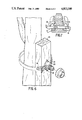
- FIG. 7 Shows a cross-sectional view of a portion of a clip according to one aspect of the present invention, in use.
- the body portion 1 includes protrusions 2 and 3 extending outwardly from one side thereof. Extending between said protrusion 2 and 3 is a slot 4. In one preferred form of the invention, the slot 4 opens into a bore or cavity 5, the bore or cavity 5 extending through the body portion 1.
- the bore 5 is provided with a rib or ridge 6 extending at least partially along the length thereof, as shown in FIG. 2.
- At least one of the protrusions 2 or 3 is provided with a notch 7, the notch 7 extending at least partially into the slot 4.
- the protrusions 2 and 3 are substantially curved, so as to be substantially semi-circular in shape, in one preferred form of the invention.
- the protrusions 2 and 3 form a substantially circular protrusion, with the slot 4 extending substantially through the center thereof.
- the protrusions 2 and 3 are at least partially threaded, as will be further described hereinafter.
- a clip according to the present invention also includes a securing portion in the form of a nut 8.
- the nut 8 has a cavity 9 therein.
- the cavity 9 extends through the nut 8. However, it will be appreciated that the cavity 9 may extend only partially through the nut 8.
- the nut 8 also comprises a lower portion 11 and an upper portion 12.
- the upper portion 12 is of lesser diameter than the lower portion 11.
- the lower portion 11 further comprises an extension 13 extending around the periphery thereof.
- the upper portion 12 is provided with a series of spaced apart radial ribs 14, which assist in the tightening of the nut 8 relative to the body portion 1, as will be further described hereinafter.
- a clip according to the present invention is preferably used in conjunction with an elongate strip of material.
- an elongate strip of material according to one preferred form of the invention comprises a substantially flexible strip with at least one opening extending therethrough.
- the elongate strip of material 16 as shown in FIG. 5 comprises a series of openings 15 therein. This allows for straight forward and convenient adjustment of the length of the strip of material relative to the clip, during use, as will be further described hereinafter.
- a clip according to the present invention may be used to facilitate the supporting and securing of an article, such as for example a plant, tree or the like, relative to a suitable support.
- At least a portion of one end of the elongate strip of material 16 is located within the bore 5 of the body portion 1.
- the elongate strip of material 16 may be releasably engaged or secured relative to the body portion 1, by engagement of at least one opening 15 of the elongate strip of material 16 about or adjacent the rib or ridge 6, as shown in FIG. 7. Thus, at least one portion of the elongate strip of material 16 is secured relative to the body portion 1.
- At least a portion of the elongate strip of material 16 is then located about or around an article to be secured and supported.
- the elongate strip of material 16 may be located around or about a trunk of a young tree, so that the trunk is located within the space 17.
- a further portion of the elongate strip of material 16 is then located within the bore or cavity 5 of the body portion 1.
- a substantially free end of the elongate strip of material 16 is located within the bore 5 of the body portion 1.
- an article (such as for example a tree) to be secured and supported is secured relative to a wire, for example a wire of a fence or the like.
- the wire 18 is located at least partially within the bore 5 of the body portion 1, by movement of the wire 15 through the slot 4.
- the wire 18 may need to be forced past the notch 7, which then acts as a retaining means. Considerable force is then required in order to remove the wire 18 from the slot 4.
- the wire 18 is moved through the slot 4, and at least a portion thereof is located within the bore 5, so as to be juxtaposed at least a portion of the elongate strip of material 16.
- the locking nut 8 is releasably engaged with the body portion 1.
- the locking nut 8 is releasably engaged with a body portion 1 by securing the locking nut 8 onto and about the protrusions 2 and 3.
- the locking nut 8 is secured firmly against the body portion 1.
- the locking nut 8 may be tightened by turning the same in the appropriate direction, an engagement of the nut 8 and body portion 1 being facilitated by applying pressure against the ribs 14, by hand or by use of a suitable tool.
- the extension 13 extending around the periphery of the nut 8 comes into contact with the wire 18 and the elongate strip of material 16. By forcing the extension 13 against the wire 18, the same are further secured relative to the clip.
- the nut 8 In order to release engagement of the nut 8 and the body portion 1, the nut 8 is turned in the opposite direction, thereby loosening the nut and removing the nut from the body portion 1.
- the clip may be removed, or adjusted relative to the elongate strip of material 16, and article to be secured and the like.
- FIGS. 6 and 7 Another preferred form of the invention is shown in FIGS. 6 and 7.
- the body portion 20 is substantially similar to the body portion 1, as shown in FIGS. 1 to 5 of the accompanying drawings.
- the body portion 20 is further provided with two extensions 21 and 22, extending outwardly from opposite sides thereof.
- the extensions 21 and 22 are provided with openings therein, which allow for the clip according to the present invention to be attached or fastened to a suitable support, such as, for example, a post 23.
- a suitable support such as, for example, a post 23.
- the clip provided in this preferred form of the invention is substantially similar in use to that shown in FIGS. 1 to 5, except that the wire 18 is not required.
- the body portion 20 is attached by means of the extensions 21 and 22 to the support means, by means of stapling, nailing and the like.
- the two portions of the elongate strip of material 16 only pass through the bore or cavity 5.
- a further advantage to be gained by securing the nut 8 firmly against the wire 18 is that movement in the direction indicated by the arrow A in FIG. 5 is prevented, or at least minimized. In effect, movement of the clip is prevented or minimized and therefore the plant or other article which is being supported and secured by the clip is prevented from movement relative to the wire. This is a particular advantage in conditions where the plant or other article is likely to move or be moved no matter which may otherwise cause damage to it.
- the elongate strip of material 16 may take other forms. There may be provided only one or two openings 15, or a plurality of openings 15, for example, extending entirely along the length of the elongate strip of material 16.
- the elongate strip of material 16 may be provided with no openings 15 therein, the ends thereof being secured within the wall 5 of the body portion 1 by other means.
- at least one end thereof may be integrally formed with the body portion 1.
- means of engaging the nut 8 with the protrusions 2 and 3 may take other forms.
- the protrusions 2 and 3 may be provided with a single ridge extending around the circumference thereof, the locking nut 8 being provided with a corresponding indent or recess therein, extending around an inner surface of the cavity 9.
- the nut 8 and body 1 would be releasably engaged one with the other by location of the ridge within the recess.
- protrusions there may be provided with the number of protrusions extending outwardly from the body portion 1.
- a clip according to the present invention may be formed of any suitable material and from any suitable technique.
- the clip may be formed of a suitable plastics material and preferably the elongate strip of materials is formed of a flexible material, for example, a plastic material. It is envisaged, however, that other materials may also be used to advantage.
- the clip according to the present invention may be formed by any suitable technique, according to the material used.
- molding or extrusion of a plastic material may be used to advantage.
- the body portion 1 according to the present invention is formed as an integral unit, and the securing nut 8 is also formed as an integral unit. It is also envisaged that the elongate strip of material is formed as an integral unit, however, in one preferred form of the invention the body portion 1 and elongate strip of material may be formed as an integral unit, such that one end of the elongate strip of material extends outwardly from the body portion 1.
- a clip suitable for use in supporting and securing plants and the like relative to a supporting means, such as for example, a wire, post and the like.
- the clip is simple and inexpensive to manufacture and is straight forward and useful in operation and use.
Landscapes
- Engineering & Computer Science (AREA)
- Mechanical Engineering (AREA)
- General Engineering & Computer Science (AREA)
- Clamps And Clips (AREA)
- Supports For Plants (AREA)
Abstract
Description
Claims (5)
Applications Claiming Priority (2)
| Application Number | Priority Date | Filing Date | Title |
|---|---|---|---|
| NZ21727586 | 1986-08-20 | ||
| NZ217275 | 1986-08-20 |
Publications (1)
| Publication Number | Publication Date |
|---|---|
| US4813109A true US4813109A (en) | 1989-03-21 |
Family
ID=19921747
Family Applications (1)
| Application Number | Title | Priority Date | Filing Date |
|---|---|---|---|
| US07/087,418 Expired - Fee Related US4813109A (en) | 1986-08-20 | 1987-08-20 | Clip for fastening the ends of an elongate flexible band |
Country Status (2)
| Country | Link |
|---|---|
| US (1) | US4813109A (en) |
| JP (1) | JPS63120908A (en) |
Cited By (10)
| Publication number | Priority date | Publication date | Assignee | Title |
|---|---|---|---|---|
| WO1993010728A1 (en) * | 1991-12-05 | 1993-06-10 | Danek Medical, Inc. | Split eyebolt for spinal rod |
| USD427053S (en) * | 1998-02-09 | 2000-06-27 | Masco Corporation Of Indiana | Fastener nut |
| US6792712B1 (en) * | 2003-04-29 | 2004-09-21 | Susan M. Houg-Blymyer | Fishing line leader holder system |
| US20070290100A1 (en) * | 2006-06-15 | 2007-12-20 | Panduit Corp. | Cable Mount for Cable Trays |
| US20090139064A1 (en) * | 2007-12-04 | 2009-06-04 | Norma Germany Gmbh | Worm thread clamp |
| US20100171003A1 (en) * | 2007-03-08 | 2010-07-08 | Panduit Corp. | Common Bonding Network Clamp |
| WO2015167346A1 (en) * | 2014-05-02 | 2015-11-05 | Rolling Stone Cleaning Co Limited | Plant support |
| US20170023048A1 (en) * | 2011-01-17 | 2017-01-26 | Thomas M. Espinosa | Checker nut for locking a threaded body to a threaded rod and concrete reinforcement assembly |
| US10266324B2 (en) | 2016-09-20 | 2019-04-23 | Michael William Horton | Adjustable fastening device and method of using same |
| US20210270308A1 (en) * | 2020-02-28 | 2021-09-02 | Caterpillar Inc. | Nut for fluid joint assembly having thread terminus located for cracking prevention |
Families Citing this family (1)
| Publication number | Priority date | Publication date | Assignee | Title |
|---|---|---|---|---|
| KR19990049162A (en) * | 1997-12-12 | 1999-07-05 | 정몽규 | Screw band structure for cable fixing |
Citations (12)
| Publication number | Priority date | Publication date | Assignee | Title |
|---|---|---|---|---|
| US1823677A (en) * | 1930-02-26 | 1931-09-15 | Charles A Bay | Electrical connecter |
| US2324780A (en) * | 1942-02-24 | 1943-07-20 | James T King | Hose clamp |
| US2374690A (en) * | 1942-02-09 | 1945-05-01 | Charles E Laue | Valve |
| US2576643A (en) * | 1950-04-20 | 1951-11-27 | Roerig Frank | Split wing nut |
| US2621383A (en) * | 1947-05-27 | 1952-12-16 | Tresidder Thomas Bruce | Hose clamp structure |
| GB868590A (en) * | 1957-07-11 | 1961-05-17 | James Stewart | Improvements in or relating to adjustable clamps for pipes |
| FR1267330A (en) * | 1960-06-13 | 1961-07-21 | Hellermann Gmbh P | Retaining device for very long parts such as cables, cable heads, pipes and the like |
| US3456547A (en) * | 1967-10-02 | 1969-07-22 | Gardner H Strong | Anchoring means |
| US3552257A (en) * | 1969-04-11 | 1971-01-05 | Atsushi Tanabe | Fastener adapted for wire cage |
| US4290171A (en) * | 1979-03-14 | 1981-09-22 | Wilcox Fred F | Clamping device |
| US4299520A (en) * | 1979-01-17 | 1981-11-10 | Iwata Bolt Kogyo Kabushiki Kaisha | Drive nut |
| US4439902A (en) * | 1980-06-05 | 1984-04-03 | Huxtable Peter John | Clip for securing around a member such as a pipe |
-
1987
- 1987-08-19 JP JP62204298A patent/JPS63120908A/en active Pending
- 1987-08-20 US US07/087,418 patent/US4813109A/en not_active Expired - Fee Related
Patent Citations (12)
| Publication number | Priority date | Publication date | Assignee | Title |
|---|---|---|---|---|
| US1823677A (en) * | 1930-02-26 | 1931-09-15 | Charles A Bay | Electrical connecter |
| US2374690A (en) * | 1942-02-09 | 1945-05-01 | Charles E Laue | Valve |
| US2324780A (en) * | 1942-02-24 | 1943-07-20 | James T King | Hose clamp |
| US2621383A (en) * | 1947-05-27 | 1952-12-16 | Tresidder Thomas Bruce | Hose clamp structure |
| US2576643A (en) * | 1950-04-20 | 1951-11-27 | Roerig Frank | Split wing nut |
| GB868590A (en) * | 1957-07-11 | 1961-05-17 | James Stewart | Improvements in or relating to adjustable clamps for pipes |
| FR1267330A (en) * | 1960-06-13 | 1961-07-21 | Hellermann Gmbh P | Retaining device for very long parts such as cables, cable heads, pipes and the like |
| US3456547A (en) * | 1967-10-02 | 1969-07-22 | Gardner H Strong | Anchoring means |
| US3552257A (en) * | 1969-04-11 | 1971-01-05 | Atsushi Tanabe | Fastener adapted for wire cage |
| US4299520A (en) * | 1979-01-17 | 1981-11-10 | Iwata Bolt Kogyo Kabushiki Kaisha | Drive nut |
| US4290171A (en) * | 1979-03-14 | 1981-09-22 | Wilcox Fred F | Clamping device |
| US4439902A (en) * | 1980-06-05 | 1984-04-03 | Huxtable Peter John | Clip for securing around a member such as a pipe |
Cited By (15)
| Publication number | Priority date | Publication date | Assignee | Title |
|---|---|---|---|---|
| US5242445A (en) * | 1991-12-05 | 1993-09-07 | Danek Medical, Inc. | Split eyebolt for spinal rod |
| AU668122B2 (en) * | 1991-12-05 | 1996-04-26 | Sdgi Holdings, Inc. | Split eyebolt for spinal rod |
| WO1993010728A1 (en) * | 1991-12-05 | 1993-06-10 | Danek Medical, Inc. | Split eyebolt for spinal rod |
| USD427053S (en) * | 1998-02-09 | 2000-06-27 | Masco Corporation Of Indiana | Fastener nut |
| US6792712B1 (en) * | 2003-04-29 | 2004-09-21 | Susan M. Houg-Blymyer | Fishing line leader holder system |
| US20070290100A1 (en) * | 2006-06-15 | 2007-12-20 | Panduit Corp. | Cable Mount for Cable Trays |
| US20100171003A1 (en) * | 2007-03-08 | 2010-07-08 | Panduit Corp. | Common Bonding Network Clamp |
| US20090139064A1 (en) * | 2007-12-04 | 2009-06-04 | Norma Germany Gmbh | Worm thread clamp |
| US8132301B2 (en) * | 2007-12-04 | 2012-03-13 | Norma Germany Gmbh | Worm thread clamp |
| US20170023048A1 (en) * | 2011-01-17 | 2017-01-26 | Thomas M. Espinosa | Checker nut for locking a threaded body to a threaded rod and concrete reinforcement assembly |
| US10527083B2 (en) * | 2011-01-17 | 2020-01-07 | Cetres Holdings, Llc | Checker nut for locking a threaded body to a threaded rod and concrete reinforcement assembly |
| WO2015167346A1 (en) * | 2014-05-02 | 2015-11-05 | Rolling Stone Cleaning Co Limited | Plant support |
| US10266324B2 (en) | 2016-09-20 | 2019-04-23 | Michael William Horton | Adjustable fastening device and method of using same |
| US20210270308A1 (en) * | 2020-02-28 | 2021-09-02 | Caterpillar Inc. | Nut for fluid joint assembly having thread terminus located for cracking prevention |
| US11549546B2 (en) * | 2020-02-28 | 2023-01-10 | Caterpillar Inc. | Nut for fluid joint assembly having thread terminus located for cracking prevention |
Also Published As
| Publication number | Publication date |
|---|---|
| JPS63120908A (en) | 1988-05-25 |
Similar Documents
| Publication | Publication Date | Title |
|---|---|---|
| US5542210A (en) | Apparatus for supporting plantlife growing in a ground area | |
| US4813109A (en) | Clip for fastening the ends of an elongate flexible band | |
| US6378175B1 (en) | Resilient fastening clip for plants | |
| US4971282A (en) | Clip | |
| US5349780A (en) | Ribbed plant support poles | |
| US4520590A (en) | Tree brace system | |
| US4145840A (en) | Fastening device | |
| US4738050A (en) | Plant and tree support clamp and system | |
| US2648879A (en) | Tying and fastening device | |
| US6138407A (en) | Cross arm and trellis apparatus and method | |
| US4750293A (en) | Plant support device | |
| US6138404A (en) | Seedling growth enhancing device | |
| US5301481A (en) | Garden stake | |
| US4299052A (en) | Tree anchoring device | |
| US4454681A (en) | Method and means of securing a plant pot to a shelf | |
| AU684468B2 (en) | Agricultural and industrial tie | |
| EP0868844A1 (en) | Ties | |
| GB2306288A (en) | Plant support | |
| EP1959723B1 (en) | Plant tie | |
| EP0476517B1 (en) | Holding device | |
| KR20220077254A (en) | Clips for connecting support strings for crop protection | |
| JP3724754B2 (en) | Square cap for prop support | |
| US11730088B2 (en) | Plant hold-down bracket | |
| JPH0711B2 (en) | Tree support construction method | |
| US587365A (en) | Means for fastening vines to trellises |
Legal Events
| Date | Code | Title | Description |
|---|---|---|---|
| AS | Assignment |
Owner name: ILLINOIS TOOL WORKS INC., CHICAGO, COOK COUNTY, IL Free format text: ASSIGNMENT OF ASSIGNORS INTEREST.;ASSIGNORS:FRENCH, EDWARD C.;MCCULLY, PETER K.;REEL/FRAME:004791/0224;SIGNING DATES FROM 19871023 TO 19871029 Owner name: ILLINOIS TOOL WORKS INC., CHICAGO, COOK COUNTY, IL Free format text: ASSIGNMENT OF ASSIGNORS INTEREST;ASSIGNORS:FRENCH, EDWARD C.;MCCULLY, PETER K.;SIGNING DATES FROM 19871023 TO 19871029;REEL/FRAME:004791/0224 |
|
| FEPP | Fee payment procedure |
Free format text: PAT HOLDER CLAIMS SMALL ENTITY STATUS - SMALL BUSINESS (ORIGINAL EVENT CODE: SM02); ENTITY STATUS OF PATENT OWNER: SMALL ENTITY |
|
| AS | Assignment |
Owner name: AGFAST CORPORATION, CALIFORNIA Free format text: ASSIGNMENT OF ASSIGNORS INTEREST.;ASSIGNOR:ILLINOIS TOOL WORKS, INC.;REEL/FRAME:006299/0133 Effective date: 19920825 |
|
| FPAY | Fee payment |
Year of fee payment: 4 |
|
| FEPP | Fee payment procedure |
Free format text: PAYOR NUMBER ASSIGNED (ORIGINAL EVENT CODE: ASPN); ENTITY STATUS OF PATENT OWNER: SMALL ENTITY |
|
| FPAY | Fee payment |
Year of fee payment: 8 |
|
| REMI | Maintenance fee reminder mailed | ||
| LAPS | Lapse for failure to pay maintenance fees | ||
| FP | Lapsed due to failure to pay maintenance fee |
Effective date: 20010321 |
|
| STCH | Information on status: patent discontinuation |
Free format text: PATENT EXPIRED DUE TO NONPAYMENT OF MAINTENANCE FEES UNDER 37 CFR 1.362 |