US48094A - Improvement in the mode of operating churns - Google Patents
Improvement in the mode of operating churns Download PDFInfo
- Publication number
- US48094A US48094A US48094DA US48094A US 48094 A US48094 A US 48094A US 48094D A US48094D A US 48094DA US 48094 A US48094 A US 48094A
- Authority
- US
- United States
- Prior art keywords
- shaft
- mode
- improvement
- churns
- operating
- Prior art date
- Legal status (The legal status is an assumption and is not a legal conclusion. Google has not performed a legal analysis and makes no representation as to the accuracy of the status listed.)
- Expired - Lifetime
Links
- 238000009432 framing Methods 0.000 description 6
- 238000004804 winding Methods 0.000 description 6
- 210000002683 Foot Anatomy 0.000 description 2
- 235000014121 butter Nutrition 0.000 description 2
- 239000006071 cream Substances 0.000 description 2
- 230000000694 effects Effects 0.000 description 2
Images
Classifications
-
- F—MECHANICAL ENGINEERING; LIGHTING; HEATING; WEAPONS; BLASTING
- F03—MACHINES OR ENGINES FOR LIQUIDS; WIND, SPRING, OR WEIGHT MOTORS; PRODUCING MECHANICAL POWER OR A REACTIVE PROPULSIVE THRUST, NOT OTHERWISE PROVIDED FOR
- F03G—SPRING, WEIGHT, INERTIA OR LIKE MOTORS; MECHANICAL-POWER PRODUCING DEVICES OR MECHANISMS, NOT OTHERWISE PROVIDED FOR OR USING ENERGY SOURCES NOT OTHERWISE PROVIDED FOR
- F03G1/00—Spring motors
Definitions
- This invention relates to a new and improved means for operating churns, whereby manual labor for that purpose is dispensed with, as hereinafter fully shown and described.
- A represents a framing in which a quadrilateral or other proper shaped cream-box, B, is placed, and O O are two dashers which work in the box B and have their rods D D connected at their upper ends by links a a to cross-heads or horizontal rods E E, the ends of which work in grooves in the sides of uprightsb of the framing.
- These cross heads or rods E E are connected by pitmen F F to cranks G G, having a reverse position on a horizontal shaft, H, so that when said shaft H is rotated the dashers C C will rise and fall and work or move in opposite directions rela tively with each other, as Will be fully understood by referring to the drawing.
- 0 is a cylindrical box or case, secured in the framing A below shaft N, and having within it a coil or barrel spring, which is connected to a shaft, I, having a cone-pulley, Q, upon it, around which a cord, R, is wound, said cord also winding over a drum, S, on shaft N,
- the shaft N has a pulley, T, upon it, against which a bar or plate, U, may be pressed with greater or less pressure by means of a screw, V.
- This bar or plate U serves as abrake to regulate or control the power of the spring and the speed of the dashers, as may be required.
- the operation is as follows:
- the coil or barrel spring is wound up by turning the shaft N through the medium of a crank-or key, the cord B being wound upon the drum S, and the wheel M remaining stationary in consequence of not being connected with shaft N when the latter is turned for thus winding up thespring.
- the coil or barrel spring rotates shaft N through the medium of the cord R, the gradually-diminishing power of the spring being compensated for by the cone Q, which is in effect a fusee, the cord R winding on Q from its larger to its smaller or outer end.
- Motion is communicated from the shaft N to shaft K by means of the gearing L M, and motion communicated to shaft H from K by means of the gearing J I.
- the churn may be operated without any manual application of power, and thereby much labor will be saved.
- the spring of course must be of such a size and strength as to operate the churn a sufficie'nt length of time to produce all the butter contained in the cream.
Description
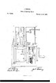
JQ'REDDING. Mode of Operating Chums.
Patented June 6, 1865;
wilgE-S s a r. Washulglo UNITED STATES PATENT OFFICE.
JACOB BEDDING, or New CASTLE, INDIANA.
IMPROVEMENT IN THE MODE OF OPERATING CHURNS.
Specification forming part of Letters Patent No. 48.094, dated June 6, 1865.
To all whom it may concern:
Be it known that I, JACOB BEDDING, of New Castle, in the county of Henry and State of Indiana, have inventedanew and Improved Means for Operating Churns; and I do hereby declare that the following is a full, clear, and exact description thereof, which will enable others skilled in the art to make and use the same, reference being had to the accompanying drawing, forming a part of this specification. I
The drawing Iepresents a sectional elevation of my invention.
This invention relates to a new and improved means for operating churns, whereby manual labor for that purpose is dispensed with, as hereinafter fully shown and described.
A represents a framing in which a quadrilateral or other proper shaped cream-box, B, is placed, and O O are two dashers which work in the box B and have their rods D D connected at their upper ends by links a a to cross-heads or horizontal rods E E, the ends of which work in grooves in the sides of uprightsb of the framing. These cross heads or rods E E are connected by pitmen F F to cranks G G, having a reverse position on a horizontal shaft, H, so that when said shaft H is rotated the dashers C C will rise and fall and work or move in opposite directions rela tively with each other, as Will be fully understood by referring to the drawing. On one end of the shaft H there is a beveLpinion, I, into which a bevel-wheel, J, on a vertical shaft,
' K, gears, the latter having a bevel-pinion, L,
upon it, which gears into a bevel-wheel, M, on ahorizontal shaft, N, the wheel M being placed loosely 011 shaft N, but connected to it bya ratchet, o, and paw] (I, so that said wheel will be turned when the shaft N is turned in one direction, but allowed to remain stationary when turned in the opposite direction.
0 is a cylindrical box or case, secured in the framing A below shaft N, and having within it a coil or barrel spring, which is connected to a shaft, I, having a cone-pulley, Q, upon it, around which a cord, R, is wound, said cord also winding over a drum, S, on shaft N,
and serving as a means for transmitting the power of the spring to the shaft N and machinery connected therewith. The shaft N has a pulley, T, upon it, against which a bar or plate, U, may be pressed with greater or less pressure by means of a screw, V. This bar or plate U serves as abrake to regulate or control the power of the spring and the speed of the dashers, as may be required.
The operation is as follows: The coil or barrel spring is wound up by turning the shaft N through the medium of a crank-or key, the cord B being wound upon the drum S, and the wheel M remaining stationary in consequence of not being connected with shaft N when the latter is turned for thus winding up thespring. The coil or barrel spring rotates shaft N through the medium of the cord R, the gradually-diminishing power of the spring being compensated for by the cone Q, which is in effect a fusee, the cord R winding on Q from its larger to its smaller or outer end. Motion is communicated from the shaft N to shaft K by means of the gearing L M, and motion communicated to shaft H from K by means of the gearing J I. By this arrangement it will be seen that the churn may be operated without any manual application of power, and thereby much labor will be saved. The spring of course must be of such a size and strength as to operate the churn a sufficie'nt length of time to produce all the butter contained in the cream.
I am aware that helical springs and fusees have before been used for driving churns.
While. disclaiining novelty in the separate devices of which my invention is made up, I claim and desire to secure by Letters Patent The general arrangement of the Vertical dashers O D, pitman F, crank-shaft GH, gearing I J K L M, drum S, cord R, pulley Q, and springbox 0, all as herein described, and for the purposes set forth.
JACOB BEDDING.
Witnesses:
THOMAS B. BEDDING, F. E. BARNARD.
Publications (1)
| Publication Number | Publication Date |
|---|---|
| US48094A true US48094A (en) | 1865-06-06 |
Family
ID=2117649
Family Applications (1)
| Application Number | Title | Priority Date | Filing Date |
|---|---|---|---|
| US48094D Expired - Lifetime US48094A (en) | Improvement in the mode of operating churns |
Country Status (1)
| Country | Link |
|---|---|
| US (1) | US48094A (en) |
-
0
- US US48094D patent/US48094A/en not_active Expired - Lifetime
Similar Documents
| Publication | Publication Date | Title |
|---|---|---|
| US48094A (en) | Improvement in the mode of operating churns | |
| US328830A (en) | Motor | |
| US41107A (en) | Improvement in churn-powers | |
| US148922A (en) | Llvlprovesviemt in churns | |
| US50687A (en) | Improvement in mechanical movements | |
| US639470A (en) | Regulator for power or propeller shafts. | |
| US233734A (en) | Steam-engine governor | |
| US506926A (en) | Motor | |
| US215383A (en) | Improvement in horse-powers | |
| US512896A (en) | penuela | |
| US43738A (en) | Improvement in horse-powers | |
| US155478A (en) | Improvement in spring-motors | |
| US215435A (en) | Improvement in automatically and positively adjustable cranks | |
| US44505A (en) | Improved churn | |
| US131215A (en) | Improvement in apparatus for multiplying power | |
| US115379A (en) | Improvement in motive powers for sewing-machines | |
| US231774A (en) | Motor | |
| US191948A (en) | Improvement in mechanical movements | |
| US409231A (en) | Motor | |
| US285372A (en) | Device for converting motion | |
| US322798A (en) | Gearing for reverse-shafts | |
| US630899A (en) | Power-transmitting mechanism. | |
| US238518A (en) | Mechanism for transmission of power and imparting motion | |
| US312307A (en) | Motor | |
| US274203A (en) | Addison lance and madison yolton |