This invention relates generally to an improved closed looped power regeneration system. This is related to application Ser. No. 819,500 entitled "Radiation Augmented Electrolysis Cell for Generating Hydrogen and Oxygen" and application Ser. No. 814,031 entitled "Hydrogen and Oxygen Generation System". It is also related to Ser. No. 804,518 entitled "Solar Augmented Power System" all of which are assigned to the common assignee herewith.
In the past, efforts have been made to generate molecular hydrogen and chlorine for use as primary fuel reagents in a combustion chamber. Such hydrogen and chlorine are combined to form HCl at high pressures and temperatures in order to drive a suitable output device, such as, a turbine. The difficulty has been to recycle the hydrogen chloride efficiently to regenerate molecular hydrogen and chlorine for continuous use in the power system.
In the past as disclosed in Melor's Comprehensive Treatise on Inorganic and Theoretical Chemistry, Volume 3, 1923, pages 80 and 81 and as disclosed in Japanese Patent Publication (Kokai) No. 51-54892, techniques are disclosed for the generation of hydrogen and chlorine from HCl. However, neither reference teaches both the generation of hydrogen and chlorine in a practical system for generating power.
In the aforementioned application, Ser. No. 814,031 entitled "Augmented Power System", a reactor chamber is provided having an input for a reactor material such as a halogen or interhalogen. Radiation is applied to the chamber to disassociate the reaction materials in the chamber and to provide reaction products having high temperatures and pressures. These materials are utilized to generate work such as to drive a turbine with the reacting materials then passing through a heat sink. The reaction materials reassociate to the original reactants and thereafter are stored for recycling. This application does not teach how to generate hydrogen and chlorine from HCl but does teach a method and apparatus for generating power in a closed loop system using halogens or interhalogens.
It is an object of this invention to provide an improved system for efficiently regenerating hydrogen and chlorine for use in a closed loop power system.
SHORT STATEMENT OF THE INVENTION
Accordingly, this invention relates to a method and apparatus for generating hydrogen and chlorine for use in a power system. Molecular hydrogen and chlorine are coupled to a combustion chamber wherein the hydrogen and chlorine combine to form HCl under high pressure and temperatures. The HCl is used to drive a suitable output device such as a turbine for generating mechanical and/or electrical power. The exhaust pipes from the turbine are directed to a heat sink where a substantial remaining portion of the heat of the HCl is removed. The HCl is then coupled to a hydrogen-chlorine regeneration system which includes a pair of reactors. In the first reactor, copper and cuprous chloride are located on beds through which the HCl is passed. The HCl combines with the copper and cuprous chloride to form hydrogen in molecular form and cuprous chloride and cupric chloride. At the same time heat extracted from the HCl after leaving the turbine is coupled to a second reactor containing cuprous chloride and cupric chloride. The heat causes the cuprous chloride and cupric chloride to form copper and molecular chlorine and cuprous chloride and molecular chlorine respectively. The molecular chlorine is then supplied back to the combustion chamber for recombination with the molecular hydrogen. After the cuprous chloride and cupric chloride have been substantially converted to copper and cuprous chloride respectively, the mode of operation has changed such that the hydrogen chloride is coupled to the second reactor to form a hydrogen and cuprous chloride. The heat from the output heat sink of the turbine is coupled to the first reactor to form molecular chlorine and cuprous chloride.
In an alternative embodiment of the invention, silver rather than copper is used as a base material wherein HCl combines with silver to form silver chloride and hydrogen. The silver chloride is then irradiated with light energy to form molecular silver and molecular chlorine. The process then repeats itself on a continuous basis.
BRIEF DESCRIPTION OF THE DRAWINGS
Other objects, features and advantages of the present invention will become more fully apparent from the following detailed description of the preferred embodiment, the appended claims and the accompanying drawings in which:
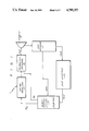
FIG. 1 is a schematic block diagram of the system of the preferred embodiment of the present invention.
FIG. 2 is a block diagram of the hydrogen-chlorine regeneration system of the preferred embodiment of the present invention when in a first mode of operation.
FIG. 3 is a schematic block diagram of the hydrogen-chlorine regeneration system of the preferred embodiment of the present invention when in a second mode of operation.
FIG. 4 is an alternative embodiment of the present invention for generating hydrogen and chlorine when in a first mode of operation; and
FIG. 5 is an alternative embodiment of the invention for generating hydrogen and chlorine when in the second mode of operation.
DETAILED DESCRIPTION OF THE PREFERRED EMBODIMENT
Refer now to FIG. 1 which is a schematic block diagram of the preferred embodiment of the system of the present invention. The molecular chlorine is coupled to a solar reactor 11 wherein electromagnetic radiation such as from the sun is directed into the chlorine to excite the chlorine to a higher energy level. The excited chlorine is coupled to a combustion chamber 12 together with molecular hydrogen wherein the hydrogen and chlorine is combined to form a hydrogen chloride. The hydrogen chloride is generated at high temperatures and pressures and is used to drive a suitable output power conversion device such as a turbine 13.
Turbine 13 is utilized to generate mechanical and/or electrical power as desired. The exhaust from the turbine is passed through a suitable heat sink 15 of a type known in the art for cooling the HCl. The heat extracted from the HCl is directed to the hydrogen-chlorine regeneration system 17 which will be described in greater detail hereinbelow. The cooled HCl is coupled to a storage unit 19 or in the alternative may be coupled directly to the regeneration system 17.
In the regeneration system, the HCl is converted back to molecular hydrogen and chlorine for coupling to the solar reactor 11 and the combustion chamber 12.
Refer now to FIG. 2 which is a more detailed block diagram of the regeneration system 17. As illustrated HCl from the storage tank 19 or directly from the heat sink 15 is coupled to the first reactor 21 wherein the HCl passes through beds of copper and cuprous chloride in the first reactor 21. The copper and cuprous chloride is preferably deposited as a refractory material, such as, alumina or a silica gel of porous pellets of, for example, 1/4 inch diameter. The following reactions take place in the reactor 21:
Cu+HCl→CuCl+1/2H.sub.2
Cu+2HCl→CuCl2 +H2
CuCl+HCl→CuCl2 +1/2H2
The reactions take place at a preferable temperature of 230° C. but may take place at a temperature of anywhere from 100° C. at the low end up to 400° C. at the upper end.
At the output of the first reactor 21 is molecular hydrogen which is coupled to a hydrogen storage tank or directly to the combustion chamber 12. In the meantime, the copper and cuprous chloride in reactor 21 is converted to cuprous chloride and cupric chloride, respectively. As aforementioned, this reaction preferably takes place in the neighborhood of 230° C. At the same time, heat from the heat sink 15 and from another source such as solar heat is coupled to a second reactor chamber 25. The temperature of the reactor chamber 25 should preferably be in the range of 700° C. to 800° C. but could be as high as 1500° C. In the second reactor chamber 25 are beds of cuprous chloride and cupric chloride. As in the reactor 21, the cuprous and cupric chloride is deposited as a suitable refractory material. Thermal energy from the heat sink and another source (not shown) is directed into this reactor. The cupric chloride is converted to cuprous chloride and chlorine while the cuprous chloride is converted to copper and molecular chlorine, each in accordance with the following reactions:
CuCl.sub.2 →CuCl+1/2Cl.sub.2
CuCl.sub.2 →Cu+Cl.sub.2
CuCl→Cu+1/2Cl.sub.2
The chlorine thus formed in reactor 25 is coupled to a suitable storage device 27 or directly to the solar reactor chamber 11.
In order to improve the efficiency of the reaction in reactor 25, an inert gas, such as, argon, helium or nitrogen may be passed through the reactor 25 to sweep the chlorine from the beds of cuprous and cupric chloride. In such a case, the chlorine will be mixed with the inert gas at the output of the reactor 25. The inert gas can be separated from the chlorine by techniques known in the art either before the chlorine is coupled to the combustion chamber 12 or thereafter.
After a time the cuprous chloride and cupric chloride in the reactor 25 becomes exhausted with only copper and cuprous chloride remaining therein. When this occurs, the system is switched as shown in FIG. 3, such that the incoming HCl from the heat sink is coupled to the second reactor 25 such that the following reactions take place therein:
Cu+HCl→CuCl+1/2H.sub.2
Cu+2HCl→CuCl.sub.2 +H.sub.2
CuCl+HCl→CuCl.sub.2 +1/2H.sub.2
At the same time, heat from the heat sink 15 is coupled to the reactor chamber 21 wherein the copper and cuprous chloride therein is converted to chlorine, copper and cuprous chloride in accordance with the following reactions:
CuCl.sub.2 →CuCl+1/2Cl.sub.2
CuCl.sub.2 →Cu+Cl.sub.2
CuCl→Cu+1/2Cl.sub.2
The chlorine thus generated in reactor 21 is coupled to the storage unit 27 whereas hydrogen formed in the reactor 25 is coupled to the hydrogen storage unit 23 or, as aforementioned, directly to the combustion chamber 12. This process repeats itself as the copper and cuprous chloride is substantially depleted.
In an alternative embodiment of the invention, silver is used as the reactant rather than copper or cuprous chloride. As shown in FIGS. 4 and 5, in the second embodiment, hydrogen chloride is coupled to a reaction chamber 31 having a bed of silver positioned on a suitable refractory material therein. When the hydrogen chloride passes over the silver, silver chloride and molecular hydrogen is formed in accordance with the following reaction:
HCl+Ag→Ag Cl+1/2H.sub.2
This reaction takes place at a temperature in the range of 150° C. to 400° C. At the same time silver chloride in reactor 33 is converted to silver and chlorine by photons from, for example, a solar flux. Preferably the light energy should be in the range of 300 to 500 nanometers which is in the blue to ultraviolet range. The photons directly disassociate the silver chloride. This reaction takes place as follows at a temperature which should not exceed 220° C.
The silver chloride can thereafter be converted to metallic silver and molecular chlorine by directing suitable electromagnetic radiation thereto in accordance with the following reaction:
AgCl+hr→Ag+1/2Cl.sub.2
While this latter reaction involves an expensive reactant, namely, silver the process can operate at lower temperature levels and thus would be more efficient in practice. Whether using silver or copper as a reactant, applicants' invention results in an approved system for generating power by combining HCl to generate high pressure and temperature exhaust products for driving a turbine and for thereafter separating the HCl into molecular hydrogen and chlorine for subsequent recombination.
While the present invention has been disclosed in connection with the prefered embodiment thereof, it should be appreciated that this embodiment can be made in keeping with the present invention.