US479230A - Compensator for signals - Google Patents
Compensator for signals Download PDFInfo
- Publication number
- US479230A US479230A US479230DA US479230A US 479230 A US479230 A US 479230A US 479230D A US479230D A US 479230DA US 479230 A US479230 A US 479230A
- Authority
- US
- United States
- Prior art keywords
- lever
- pinion
- levers
- compensator
- wire
- Prior art date
- Legal status (The legal status is an assumption and is not a legal conclusion. Google has not performed a legal analysis and makes no representation as to the accuracy of the status listed.)
- Expired - Lifetime
Links
- 230000033001 locomotion Effects 0.000 description 9
- 230000000694 effects Effects 0.000 description 2
- 230000005540 biological transmission Effects 0.000 description 1
Images
Classifications
-
- B—PERFORMING OPERATIONS; TRANSPORTING
- B61—RAILWAYS
- B61L—GUIDING RAILWAY TRAFFIC; ENSURING THE SAFETY OF RAILWAY TRAFFIC
- B61L19/00—Arrangements for interlocking between points and signals by means of a single interlocking device, e.g. central control
- B61L19/02—Interlocking devices having mechanical or fluid-pressure operation
-
- Y—GENERAL TAGGING OF NEW TECHNOLOGICAL DEVELOPMENTS; GENERAL TAGGING OF CROSS-SECTIONAL TECHNOLOGIES SPANNING OVER SEVERAL SECTIONS OF THE IPC; TECHNICAL SUBJECTS COVERED BY FORMER USPC CROSS-REFERENCE ART COLLECTIONS [XRACs] AND DIGESTS
- Y10—TECHNICAL SUBJECTS COVERED BY FORMER USPC
- Y10T—TECHNICAL SUBJECTS COVERED BY FORMER US CLASSIFICATION
- Y10T74/00—Machine element or mechanism
- Y10T74/21—Elements
- Y10T74/2142—Pitmans and connecting rods
- Y10T74/2151—Longitudinally adjustable
Definitions
- the invention described in this specification which is a division of application Serial No. 421,165, filed February 6, 1892, relates generally to certain improvements in compensators for signal connections of that class or kind described and claimed in Letters Patent No. 470,148, granted March 1, 1892; but said improvements relate more particularly to that species of compensator wherein are employed two pairs of connected bellcrank levers, one member of each pair being connected to an operating-lever and the other member of each pair to a signal, and mechanism whereby motion is transmitted from the lever-operated member of one pair to the signal-operating member of the other pair.
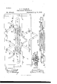
- Figure 1 is a top plan view of my improved compensator.
- Fig. 2 is a side elevation of the same.
- Fig. 3 is a sectional view, the plane of section being indicated by the line a: as, Fig. 1.
- the bed-plate 1 of the compensator is provided at its ends with suitable flanges or feet 2, wherebyit may be secured to the track-ties or any other suitable foundation.
- Bell-crank levers 3 and 4 are pivotally mounted on the bed-plate in suitable relation to each other and have their arms 3 and 4 connected by links 5 to corresponding arms 6 and 7 b of bellcrank levers 6 and 7, also pivotally mounted on the bed-plate in suitable relation to each other and to the levers 3 and 4.
- the arms 3 and 4 of the levers 3 and 4 are connected by wires 8 and 9 or other suitable means to an operating-lever, and the arms 6 and 7 a of the levers 6 and 7 are connected by wires 10 and 11 to the signal, or the levers 3 and 4 may be connected to the signal and the levers 6 and 7 to the operating-lever.
- the connections to the lever and signal are flexible, it will be evident by reference to Fig. 1 that the motion imparted to the lever 4 by a pull on the wire 9 must be transmitted to the lever 6 in order to pull the wire 10, as the lever 7 is so shifted by the lever 4 when actuated by a pull on the wire 9 as to exert a push on the wire 11, and will not therefore operate to shift the signal.
- Asimilar movement of the lever 3 to shift a signal must be transferred to the lever 7.
- curved racks 12 are attached to or formed on the ends of the arms a of the several levers 3, 4, 6, and 7, the racks of the arms of the levers 3 and 4 intermeshing with a pinion 13 on opposite sides thereof, while the racks on the arms of the levers 6 and 7 similarly engageapinion 14.
- the journals of these pinions 13 and 14 are mounted in horizontal slots 15, formed in the bedplate 1 and the cap-plate 16, which is attached to the bed-plate by suitable bolts 17.
- This block is slotted for the reception of the journal of the pinion 14 and is mounted in suitable guides on the bedplate 1.
- the block is normally held away from the bar 31 by a spring 21, as shown in Figs. 1 and 3.
- the serrated end of the bar 31 is supported in proper relation to theblock by suitable guideways on the bed-plate.
- the operating-lever when shifted pulls the wire 9 and lever 4 in the direction of the arrow 01, the lever 7 being thereby shifted in the opposite direction and slackening the wire 11.
- the pinion 14 begins to rotate, being actuated by the lever 7, the block 20 is raised into engagement with the bar 31.
- the continued rotation of the pinion 14 shifts the lever 6 in the direc tion of the arrow (1, and through the wire 10 shifts the signal, the wire 11 being slackened, as stated.
- the lever 6 is also actuated by the lever 4 through the medium of the pinion 13 and lever 3, which is shifted by the rotation of the pinion 13 an equal amount in a direction opposite to that of the movement of the lever 4, thereby slackening the wire 8.
- a compensator for signals the combination of two pairs of connected bell-crank levers, one member of each pair being connected to an operating-lever and the other member of each pair to a signal, rack-bars secured to one arm of a member of each pair of bel1-cranks, and a pinion intermeshing with said rack-bars, substantially as set forth.
- a compensator for signals the combination of two pairs of connected bell-crank levers, one member of each pair being connected to an operating-lever and the other member of each pair to a signal, rack-bars secured to one arm of a member of each pair of bell-cranks, a laterally-movable pinion engaging said rack-bars, and a spring for shifting the pinion, substantially as set forth.
- a compensator for signals the combination of two pairs of connected bell-crank levers, one member of each pair being connected to an operating-lever and the other member of each pair to a signal, rack-bars secured to one arm of a member of each pair of bell-cranks, a movable pinion engaging said rack-bars, a spring for shifting the pinion, and a lock for holding the pinion as against movement, substantially as set forth.
Landscapes
- Engineering & Computer Science (AREA)
- Mechanical Engineering (AREA)
- Transmission Devices (AREA)
Description
(No Model.)
J. J. TURNER. GOMPENSATOR FOR SIGNALS.
No. 479,230. Patented July 19, \1892.
INVEIITOITOVZ j WITNESSES:
' UNITED STATES PATENT OFFICE.
JAMES J. TURNER, OF PITTSBURG, PENNSYLVANIA.
COMPENSATOR FOR SIGNALS.
SPECIFICATION forming part of Letters Patent No. 479,230, dated July 19, 1892.
Original application filed February 6, 1392- Serial No. 421,165. Divided and this application filed May 25, 1892- Serial No. 434,345. (No model.)
To all whom it may concern.-
Be it known that I, JAMES J. TURNER, a citizen of the United States, residing at Pittsburg, in the county of Allegheny and State of Pennsylvania, have invented or discovered a certain new and useful Improvement in Compensators for Signals, of which improvement the following is a specification.
The invention described in this specification, which is a division of application Serial No. 421,165, filed February 6, 1892, relates generally to certain improvements in compensators for signal connections of that class or kind described and claimed in Letters Patent No. 470,148, granted March 1, 1892; but said improvements relate more particularly to that species of compensator wherein are employed two pairs of connected bellcrank levers, one member of each pair being connected to an operating-lever and the other member of each pair to a signal, and mechanism whereby motion is transmitted from the lever-operated member of one pair to the signal-operating member of the other pair.
In the accompanying drawings, forming a part of this specification, Figure 1 is a top plan view of my improved compensator. Fig. 2 is a side elevation of the same. Fig. 3 is a sectional view, the plane of section being indicated by the line a: as, Fig. 1.
The bed-plate 1 of the compensator isprovided at its ends with suitable flanges or feet 2, wherebyit may be secured to the track-ties or any other suitable foundation. Bell-crank levers 3 and 4 are pivotally mounted on the bed-plate in suitable relation to each other and have their arms 3 and 4 connected by links 5 to corresponding arms 6 and 7 b of bellcrank levers 6 and 7, also pivotally mounted on the bed-plate in suitable relation to each other and to the levers 3 and 4. The arms 3 and 4 of the levers 3 and 4 are connected by wires 8 and 9 or other suitable means to an operating-lever, and the arms 6 and 7 a of the levers 6 and 7 are connected by wires 10 and 11 to the signal, or the levers 3 and 4 may be connected to the signal and the levers 6 and 7 to the operating-lever. As the connections to the lever and signal are flexible, it will be evident by reference to Fig. 1 that the motion imparted to the lever 4 by a pull on the wire 9 must be transmitted to the lever 6 in order to pull the wire 10, as the lever 7 is so shifted by the lever 4 when actuated by a pull on the wire 9 as to exert a push on the wire 11, and will not therefore operate to shift the signal. Asimilar movement of the lever 3 to shift a signal must be transferred to the lever 7.
In order to effect simultaneous and'equal movement of all the levers, curved racks 12 are attached to or formed on the ends of the arms a of the several levers 3, 4, 6, and 7, the racks of the arms of the levers 3 and 4 intermeshing with a pinion 13 on opposite sides thereof, while the racks on the arms of the levers 6 and 7 similarly engageapinion 14. The journals of these pinions 13 and 14 are mounted in horizontal slots 15, formed in the bedplate 1 and the cap-plate 16, which is attached to the bed-plate by suitable bolts 17.
In order to maintain the wires 8, 9, 10, and 11 at a uniform tension under all atmospheric conditions, the journals of the pinions 13 and 14 are connected by springs 18, which are placed under such tension as to draw the pinions toward each other, and as the pinions are in engagement with the rack-bars 12 of the several levers the .wires on both ends of the compensator will be subjected to the same tension. In case one of the wires, as 8, should stretch more than the wire 9 the pull of the springs 18 on the journals of the pinion 13, the lever 4 being held stationary by its wire 9, will cause the pinion to roll on the rack of the lever 4 in the direction of the arrow 0, and thereby shift the lever 3 in the same direction until the tension of the wire 8 is equal, or approximately so, to that of the wire 9. The adjustment of the tension of the wires 10 and 11 is effected automatically in the same manner as that of the wires 8 and 9.
In order to effect a transmission of movement from one of the levers to another through the medium of the pinions 13 and 14, it is necessary to lock said pinions as against any movement toward or from each other. This locking is effected by a bar 31, having one end attached to the journal of one of the pinions, as 13, while the opposite end extends toward and beyond the other pinion and is provided on its under side with a series of teeth, as shown in Figs. 1 and 2. On the journal of the pinion 14 is secured a cam 19, which as the journal begins to rotate engages a shoulder on the sliding block 20 and raises said block until a series of teeth on its upper face engage the teeth or serrations on the bar 31. This block is slotted for the reception of the journal of the pinion 14 and is mounted in suitable guides on the bedplate 1. The block is normally held away from the bar 31 by a spring 21, as shown in Figs. 1 and 3. The serrated end of the bar 31 is supported in proper relation to theblock by suitable guideways on the bed-plate.
When the parts are in the position shown in Fig. 1, the operating-lever (not shown) when shifted pulls the wire 9 and lever 4 in the direction of the arrow 01, the lever 7 being thereby shifted in the opposite direction and slackening the wire 11. As the pinion 14 begins to rotate, being actuated by the lever 7, the block 20 is raised into engagement with the bar 31. The continued rotation of the pinion 14 shifts the lever 6 in the direc tion of the arrow (1, and through the wire 10 shifts the signal, the wire 11 being slackened, as stated. The lever 6 is also actuated by the lever 4 through the medium of the pinion 13 and lever 3, which is shifted by the rotation of the pinion 13 an equal amount in a direction opposite to that of the movement of the lever 4, thereby slackening the wire 8.
It will be seen from the foregoing that the several parts of the device operate synchronously and equally on the movement of one of. the parts.
I claim herein as my invention- 1. In a compensator for signals, the combination of two pairs of connected bell-crank levers, one member of each pair being connected to an operating-lever and the other member of each pair to a signal, rack-bars secured to one arm of a member of each pair of bel1-cranks, and a pinion intermeshing with said rack-bars, substantially as set forth.
2. In a compensator for signals, the combination of two pairs of connected bell-crank levers, one member of each pair being connected to an operating-lever and the other member of each pair to a signal, rack-bars secured to one arm of a member of each pair of bell-cranks, a laterally-movable pinion engaging said rack-bars, and a spring for shifting the pinion, substantially as set forth.
3. In a compensator for signals, the combination of two pairs of connected bell-crank levers, one member of each pair being connected to an operating-lever and the other member of each pair to a signal, rack-bars secured to one arm of a member of each pair of bell-cranks, a movable pinion engaging said rack-bars, a spring for shifting the pinion, and a lock for holding the pinion as against movement, substantially as set forth.
In testimony whereof I have hereunto set my hand.
JAMES J. TURNER. Witnesses:
DARWIN S. WOLCOTT, R. H. WHITTLESEY.
Publications (1)
| Publication Number | Publication Date |
|---|---|
| US479230A true US479230A (en) | 1892-07-19 |
Family
ID=2548084
Family Applications (1)
| Application Number | Title | Priority Date | Filing Date |
|---|---|---|---|
| US479230D Expired - Lifetime US479230A (en) | Compensator for signals |
Country Status (1)
| Country | Link |
|---|---|
| US (1) | US479230A (en) |
Cited By (1)
| Publication number | Priority date | Publication date | Assignee | Title |
|---|---|---|---|---|
| TWI726909B (en) * | 2015-09-09 | 2021-05-11 | 美商伊雷克托科學工業股份有限公司 | Laser processing apparatus, methods of laser-processing workpieces and related arrangements |
-
0
- US US479230D patent/US479230A/en not_active Expired - Lifetime
Cited By (1)
| Publication number | Priority date | Publication date | Assignee | Title |
|---|---|---|---|---|
| TWI726909B (en) * | 2015-09-09 | 2021-05-11 | 美商伊雷克托科學工業股份有限公司 | Laser processing apparatus, methods of laser-processing workpieces and related arrangements |
Similar Documents
| Publication | Publication Date | Title |
|---|---|---|
| US479230A (en) | Compensator for signals | |
| US470148A (en) | Compensator for signals | |
| US1670006A (en) | Wireworking machine | |
| US486303A (en) | Compensator for signals | |
| US515722A (en) | Compensator for signals | |
| US1251024A (en) | Spring-switch. | |
| US528962A (en) | And george f | |
| US6683A (en) | And john w | |
| US445723A (en) | Island | |
| US543778A (en) | Switch and signal mechanism | |
| US512610A (en) | Ernst gessner | |
| US344104A (en) | Continuous rolling-mill | |
| US403195A (en) | Apparatus for operating railway-switches | |
| US367214A (en) | Nicolas koenig | |
| US904281A (en) | Narrow-ware loom. | |
| US354407A (en) | James lorenzo gage | |
| US813141A (en) | Machine for bending cast-iron. | |
| US1081708A (en) | Point-lever for use on railways and the like. | |
| US943967A (en) | Bending apparatus. | |
| US481922A (en) | Samuel w | |
| US1382020A (en) | Valve-operating lever | |
| US909232A (en) | Brake-rigging for railway-cars. | |
| US714120A (en) | Automatic stop mechanism for wire-mills. | |
| US497754A (en) | Planing machine for metal | |
| US406213A (en) | Switch and signal apparatus |