US4789448A - Device for control of scale formation - Google Patents
Device for control of scale formation Download PDFInfo
- Publication number
- US4789448A US4789448A US06/822,025 US82202586A US4789448A US 4789448 A US4789448 A US 4789448A US 82202586 A US82202586 A US 82202586A US 4789448 A US4789448 A US 4789448A
- Authority
- US
- United States
- Prior art keywords
- water
- anode
- scale
- cathode
- particles
- Prior art date
- Legal status (The legal status is an assumption and is not a legal conclusion. Google has not performed a legal analysis and makes no representation as to the accuracy of the status listed.)
- Expired - Fee Related
Links
Images


Classifications
-
- C—CHEMISTRY; METALLURGY
- C02—TREATMENT OF WATER, WASTE WATER, SEWAGE, OR SLUDGE
- C02F—TREATMENT OF WATER, WASTE WATER, SEWAGE, OR SLUDGE
- C02F1/00—Treatment of water, waste water, or sewage
- C02F1/48—Treatment of water, waste water, or sewage with magnetic or electric fields
- C02F1/481—Treatment of water, waste water, or sewage with magnetic or electric fields using permanent magnets
-
- C—CHEMISTRY; METALLURGY
- C02—TREATMENT OF WATER, WASTE WATER, SEWAGE, OR SLUDGE
- C02F—TREATMENT OF WATER, WASTE WATER, SEWAGE, OR SLUDGE
- C02F1/00—Treatment of water, waste water, or sewage
- C02F1/46—Treatment of water, waste water, or sewage by electrochemical methods
- C02F1/4602—Treatment of water, waste water, or sewage by electrochemical methods for prevention or elimination of deposits
-
- Y—GENERAL TAGGING OF NEW TECHNOLOGICAL DEVELOPMENTS; GENERAL TAGGING OF CROSS-SECTIONAL TECHNOLOGIES SPANNING OVER SEVERAL SECTIONS OF THE IPC; TECHNICAL SUBJECTS COVERED BY FORMER USPC CROSS-REFERENCE ART COLLECTIONS [XRACs] AND DIGESTS
- Y10—TECHNICAL SUBJECTS COVERED BY FORMER USPC
- Y10S—TECHNICAL SUBJECTS COVERED BY FORMER USPC CROSS-REFERENCE ART COLLECTIONS [XRACs] AND DIGESTS
- Y10S204/00—Chemistry: electrical and wave energy
- Y10S204/05—Magnetic plus electrolytic
Definitions
- This invention relates to methods and means for countering the deposition of hardwater scale in containers or on the inner surfaces of conduits or apparatus in which the water is contained or through which it flows.
- a device for treating hard water to counter the deposition of scale comprising an anode and a cathode spaced apart to define a passage through which water to be treated passes during operation of the device, said anode and cathode being connected in an electrical circuit externally of the water and including the water as an electrolyte, the anode being a sacrificial anode which releases negatively charged salt particles and ions into the water during operation of the device, at least a substantial proportion of such particles and ions being non-adherent to the anode and cathode and thereby forming sites in the water for formation of crystals of scale forming impurities which remain in suspension in the water thereby reducing deposition of scale on the surfaces of vessels, pipes or the like into or through which the water subsequently flows.
- the anode is composed of a metal which is non-toxic, forms an amphoteric hydroxide in aqueous solution, and is sufficiently separated on the galvanic scale from the cathode metal to form an electrolytic current consuming cell.
- a zinc anode combined with a copper cathode.
- the zinc is preferably of high purity, that is in excess of 99% pure.
- the anode is arranged to have a mass loss rate of less than 10 ⁇ 10 -6 grammes/hour.
- the anode comprises a series of rings spaced apart axially of the device and defining a central passage for flow of water therethrough, the cathode comprising a tube surrounding said rings but electrically insulated therefrom other than by way of said electrical connection.
- the anode comprises a bar of castellated form around which the water flows during its passage through the device, the castellated bar presenting a substantial surface area to the water and the cathode comprising a tube surrounding said bar but insulated therefrom except by way of said electrical connection.
- the anode may be mounted on or retained within a support of a more rigid material having little or no electrolytic action with the material of the anode under cold water conditions.
- the support may be of stainless steel which remains anodic to copper due to the configuration of the device and the cold water operating conditions.
- Said electrical circuit may be adapted to enable an external electrical potential to be applied across the circuit to cause an externally generated current to pass through the cell.
- the circuit may be provided with means for adjusting the current passing through the cell and for monitoring the performance of the device.
- control may be effected by maintaining substantially constant the ratio of the surface area of the anode to the average maximum flow rate of water through the device for different sizes of device adapted to different operating conditions.
- the ratio of surface area in square centimetres to average maximum flow rate in litres per minute is between 1.55 and 1.75, and preferably approximately 1.65.
- the device incorporates a region of high magnetic field disposed downstream of said anode and cathode.
- a device for treating hard water to counter the deposition of scale comprising means for causing release of electrically charged particles and ions of random orientation into water flowing through the device to act as sites for formation of crystals of scale forming impurities in suspension in the water and means downstream thereof for generating a magnetic field through which said particles and ions pass during their travel through the device in suspension in the water, whereby to accelerate orientation of the particles and assist coagulation and crystal formation, thereby reducing deposition of scale on the surfaces of vessels, pipes or the like into or through which the water subsequently flows.
- Said means for causing release of particles and ions preferably comprises a sacrificial anode incorporated in an electrical circuit with a cathode and the water as electrolyte.
- Said means for generating a magnetic field preferably comprises a permanent magnet the poles of which define a passage for water passing through the device and which generates a magnetic field of 10,000 gauss or greater.
- FIG. 1 is an external side elevation of one form of device according to the invention.
- FIG. 2 is an enlarged vertical cross-section through one end of the device shown in FIG. 1;
- FIG. 3 is a cross-section on the line III--III in FIG. 2;
- FIG. 4 is a vertical cross-section through an alternative form of device
- FIG. 5 is an enlarged detail view showing a modification
- FIG. 6 is a diagram of an electrical control circuit incorporated in an alternative form of device
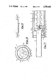
- FIG. 7 is a fragmentary cross-section through a modified form of device
- FIG. 8 is a side view of a magnetic element incorporated in the device of FIG. 7;
- FIG. 9 is a view in the direction of arrow A in FIG. 8;
- FIG. 10 is a section on the line X--X in FIG. 8.
- FIG. 11 is a view in the direction of arrow B in FIG. 8.
- the device comprises an outer casing 5 of plastics or other electrically insulating material from the opposite ends of which copper connectors 6 project for connection to a section of pipe in which the device is to be fitted.
- the copper connectors 6 are supported in end plugs 7 of plastics or other electrically insulating material and are connected at their inner ends through copper end plates 8 to a section 9 of copper tube located within and spaced from the outer casing 5 of the device.
- a support member 10 mounted within each end of the copper tube 9 is a support member 10 in the form of a cradle of plastic or other electrically insulating material incorpoating openings 10A (FIG. 3) through which liquid may flow and having a central aperture 11 (FIG. 3) through which a stainless steel rod 12 extends and is secured at each end by nuts 13 also of stainless steel.
- a bar 14 of high purity zinc preferably in excess of 99% pure and advantageously 99.99% pure.
- the bar 14 is of castellated form in order to present a substantial surface area to liquid flowing through the device in use which passes between the bar 14 and the inner surface of the copper tube 9. Longitudinal movement of the assembly consisting of the stainless steel rod 12, zinc bar 14 and support devices 10 is prevented by spacer members 15 of plastics or other electrically insulating material interposed between the end plates 8 and the support members 10.
- One of the copper end connectors 6 is electrically connected to the stainless steel rod 12 by means of an electrical circuit 16 incorporating a resistor 17 and passing through the associated end plate 8 by means of an insulated connector 18.
- Electrical connection to the zinc anode is achieved by arranging for the latter to be a tight push fit on the rod 12. This also ensures there is no gap between the anode and the rod 12 which might give rise to corrosion in use.
- the resistor controls and stabilizes the current flow in the circuit and is preferably a 0.5 watt resistor of 500 ohms or greater.
- the device In operation the device is inserted into a supply conduit of, for example, a water system.
- a supply conduit of, for example, a water system.
- the connecting members 6 and tube 9 on the one hand and the castellated bar 14 on the other hand are formed from different metals, a potential difference exists between them due to their different positions on the galvanic scale.
- liquid passes through the device it forms a conducting path allowing current to flow round the circuit formed by the wire 16.
- the liquid passing through the device is therefore subjected to a self-induced electric field which affects the electrical potential of the suspended particles in the liquid and counters the deposition of scale.
- Visual indication of correct operation may be provided by replacing the resistor 17 with a miniature moving coil ammeter 19A and associated resistor 19B as shown in FIG. 5, such that the total resistance of the ammeter plus resistor is 500 ohms or greater and the ammeter registers a significant fraction of full scale deflection when the device is operating normally. Any variation in the operating conditions, particularly a reduction or interruption of the action of the electrolytic current consuming cell, is indicated by a change in the ammeter deflection.
- FIG. 4 shows an alternative form of device in which the zinc bar of the FIGS. 1 to 3 arrangement is replaced by a plurality of rings 20 of zinc which are a tight push fit within a stainless steel support tube 21.
- the tube 21 is surrounded at each end by a bush 22 of nylon or other electrically insulating material which is mounted in turn within a copper tube 23 connected to copper end connectors 24 similar to those shown in FIGS. 1 and 2.
- the device is enclosed in a tubular outer casing 25 of plastics material fitted with electrically insulating end caps 26.
- a section of the copper tube 23 is cut away to form an opening 27 through which passes a wire 28 incorporating a resistor 29.
- the opposite ends of the wire are connected to the tubes 21 and 23 thus forming an electrical connection between the copper tube 23 which acts as the cathode and the steel tube 21 and hence the zinc rings 20 which act as the anode. It has been found that the zinc maintains the stainless steel in an anodic mode.
- the device of FIG. 4 may also be modified in the manner shown in FIG. 5 if desired.
- the device of FIGS. 2 and 3 is more suited to applications where higher flow rates are involved and greater anode surface areas are required.
- the embodiments of the device described above are passive electrolytic devices, that is, no external power source is required for the electrolytic action, the current flow deriving from electrical potential generated by chemical reaction at the surface of the electrodes.
- the effectiveness of such a device and its performance depend on the structure and condition of the electrodes and the water passing through the device and no control of the operation of the device is possible.
- suitable control means the device may be adjusted to cope with variation in conditions or build-up of coating on the electrode surfaces without ceasing to function.
- FIG. 6 shows a control circuit employing feedback to ensure that a constant current passes through the electrolytic cell device which is indicated at D.
- the main part of the circuit comprises two operational amplifiers OA1 and OA2 with associated resistors R 1 , R 2 and R L .
- Amplifier OA1 acts to polarise the anode such that an electrolytic current passes between the anode and the cathode. This current is also passed through the load resistor R L , and gives rise to a potential drop across the resistor.
- the potential at the cell end of the load resistor R L thus depends on the current flowing through the cell.
- This potential is measured by amplifiere OA2, which is an operational amplifier arranged as a unity gain buffer.
- the feedback loop is completed by resistors R 1 and R 2 which form the summing mode of amplifier OA1.
- the circuit operates such that the potential difference between the two inputs of amplifier OA1 is zero. Since the positive input is grounded, the negative input must also be at ground potential, which implies that the currents flowing through the two resistors of the summing mode are equal and opposite. Since the potential V 2 is dependent on the current flowing through the cell, the current can be controlled by adjusting V 1 . Variation of input voltage V 1 will allow the current to be set over a wide range. The polarisation potential applied to the cell by amplifier OA1 may thus be varied to take account of any variations in electrode condition or water characteristics. A feedback capacitor C F is connected across amplifier OA1 to stabilise the response of the circuit and prevent oscillations. The actual current flowing will be monitored by an ammeter or a voltmeter module A. The resitance R L is the total resistance between the electrode and ground.
- the performance of the circuit may be monitored using a comparator amplifier. This has the property that the voltage at the output changes state when the potential at one input changes from being less than the other input to greater than the other input. Failure of the circuit would be indicated by the output of amplifier OA1 going to maximum output voltage in an attempt to maintain current through the cell. By applying a reference potential V REF to one input which is slightly lower than the maximum output of amplifier OA1, if a failure occurs and amplifier OA1 goes to maximum output voltage, then the output of capacitor C1 will change state causing a visual and/or audible alarm W to be triggered.
- This control circuit will cope with such faults as:
- the total amount of crystal growth is thought to remain the same as in untreated liquid, but as a substantial proportion is in the form of suspended precipitate carried in the liquid it is withdrawn from the system with the liquid and as a result the scale formed on the internal surfaces of the system is reduced.
- the device acts as an electrolytic cell with the water flowing through the device acting as the electrolyte.
- the zinc anode is sacrificial and gives off minute particles of zinc oxide and zinc hydroxide at a controlled rate. These particles are substantially non-adherent to the anode, remain in suspension in the water and are carried out of the device by the water flow. They thus form sites for crystallization or coagulation of the impurities in the water, inhibiting scale formation on the surfaces of the pipe, container or the like.
- scale formation is reduced by virtue of association of calcium particles in the water with zinc oxide and zinc hydroxide particles released by the electrochemical action of the cell.
- the performance of the device may be improved by passage of the treated water emanating from the device through a region of high magnetic field.
- the field is preferably produced by a permanent magnet arranged such that its two poles define a passage for water passing through the device, and the magnetic field between the two poles is preferably 10,000 gauss or greater. Particles released by the anode of the electrolytic cell device form nucleation sites in the water for treatment by the magnetic field.
- FIGS. 7 to 11 show a form of magnetic device which may be incorporated at the downstream end of an electrolytic cell device.
- the magnetic device is incorporated in a device of the kind shown in FIG. 4 in which the anode comprises a plurality of zinc rings 20 through which the water to be treated flows to a copper outlet pipe 24.
- the treated water Before entering the pipe 24 the treated water passes through the magnetic device which comprises a mild steel body acting both as a return circuit and as a housing 40 enclosing a cylindrical magnet 41. Water enters the housing through an arcuate slot 42 of proportional area to the supply pipe and may pass around the sides of the magnet through a passage-way 43 and leave by way of an annular outlet slot 45.
- the inlet slot 42 may be replaced by a plurality of arcuate slots or a series of annularly arranged holes if desired.
- the entire assembly is coated with a thin layer of a non-magnetic corrosion protection material.
- Devices of the kind described inserted in a supply pipe are found to induce coagulation of the colloid or other particles and ions in the liquid.
- hard water is treated in this way the tendency to form scale deposits on the inner surfaces of conduits and containers is reduced.
- Extra devices may however be required in some cases and in the case of industrial applications.
- the internal construction of the device may be modified and different materials meeting the criteria referred to above may be employed.
- the additional magnetic treatment may be omitted if desired or may be effected by a self-contained magnetic device arranged to be fitted in the supply pipe downstream of the electrolytic device.
- the various monitoring and control means referred to may also be omitted if desired.
- the invention is also applicable to the treatment of other liquids including, for example, fuel oil.
Landscapes
- Chemical & Material Sciences (AREA)
- Water Supply & Treatment (AREA)
- Environmental & Geological Engineering (AREA)
- Hydrology & Water Resources (AREA)
- Life Sciences & Earth Sciences (AREA)
- Organic Chemistry (AREA)
- Engineering & Computer Science (AREA)
- Electrochemistry (AREA)
- Chemical Kinetics & Catalysis (AREA)
- General Chemical & Material Sciences (AREA)
- Water Treatment By Electricity Or Magnetism (AREA)
- Electrical Discharge Machining, Electrochemical Machining, And Combined Machining (AREA)
- Control Of Motors That Do Not Use Commutators (AREA)
- Vending Machines For Individual Products (AREA)
- Steam Or Hot-Water Central Heating Systems (AREA)
- Processing Of Solid Wastes (AREA)
- Refuse Collection And Transfer (AREA)
Applications Claiming Priority (2)
| Application Number | Priority Date | Filing Date | Title |
|---|---|---|---|
| GB8502078 | 1985-01-28 | ||
| GB858502078A GB8502078D0 (en) | 1985-01-28 | 1985-01-28 | Control of scale formation |
Publications (1)
| Publication Number | Publication Date |
|---|---|
| US4789448A true US4789448A (en) | 1988-12-06 |
Family
ID=10573511
Family Applications (1)
| Application Number | Title | Priority Date | Filing Date |
|---|---|---|---|
| US06/822,025 Expired - Fee Related US4789448A (en) | 1985-01-28 | 1986-01-24 | Device for control of scale formation |
Country Status (7)
| Country | Link |
|---|---|
| US (1) | US4789448A (fr) |
| EP (1) | EP0194012B1 (fr) |
| AT (1) | ATE51855T1 (fr) |
| AU (1) | AU591090B2 (fr) |
| DE (1) | DE3670278D1 (fr) |
| ES (1) | ES8701239A1 (fr) |
| GB (1) | GB8502078D0 (fr) |
Cited By (17)
| Publication number | Priority date | Publication date | Assignee | Title |
|---|---|---|---|---|
| US5359769A (en) * | 1989-03-06 | 1994-11-01 | Silveri Michael A | Installation method for pool purifier |
| US5389210A (en) * | 1989-08-18 | 1995-02-14 | Silveri; Michael A. | Method and apparatus for mounting an electrolytic cell |
| US5545310A (en) | 1995-03-30 | 1996-08-13 | Silveri; Michael A. | Method of inhibiting scale formation in spa halogen generator |
| WO1996030563A1 (fr) * | 1995-03-30 | 1996-10-03 | Ceramatec, Inc. | Dispositif pour production electrochimique de gaz efficace sur le plan coulombien |
| US5580438A (en) * | 1989-08-18 | 1996-12-03 | Silveri; Michael A. | Pool purifier attaching apparatus and method |
| US5676805A (en) | 1995-03-30 | 1997-10-14 | Bioquest | SPA purification system |
| US5752282A (en) | 1995-03-30 | 1998-05-19 | Bioquest | Spa fitting |
| US5759384A (en) | 1995-03-30 | 1998-06-02 | Bioquest | Spa halogen generator and method of operating |
| US6007693A (en) | 1995-03-30 | 1999-12-28 | Bioquest | Spa halogen generator and method of operating |
| EP1046616A2 (fr) * | 1999-02-06 | 2000-10-25 | Vallendar, Hubertus | Configuration d'électrodes pour le traitement galvanique d'un fluide en écoulement |
| USRE37055E1 (en) | 1989-08-18 | 2001-02-20 | Michael A. Silveri | Pool purifier attaching apparatus and method |
| WO2004108607A1 (fr) * | 2003-06-10 | 2004-12-16 | Marc Flettner | Dispositif pour traiter l'eau |
| US6937686B2 (en) * | 2002-09-30 | 2005-08-30 | General Electric Company | Iron control in BWR's with sacrificial electrodes |
| US20070138104A1 (en) * | 2005-12-16 | 2007-06-21 | Gabi Elgressy | Depressing precipitation of sparingly soluble salts in a water supply |
| US8187444B2 (en) | 2007-08-10 | 2012-05-29 | Eric John Kruger | Fluid treatment device |
| CN110054264A (zh) * | 2018-06-01 | 2019-07-26 | 北京中电聚能新技术有限公司 | 一种基于量子能量信息铸录的防垢阻垢方法及装置与坯料加工系统 |
| US10800677B2 (en) | 2017-02-22 | 2020-10-13 | Ecowater Systems Llc | Electrolytic zinc dosing device and method for reducing scale |
Families Citing this family (12)
| Publication number | Priority date | Publication date | Assignee | Title |
|---|---|---|---|---|
| BE1003186A4 (fr) * | 1989-09-15 | 1992-01-07 | Kritikos Eleftherios | Procede de traitement d'eau et dispositif pour un tel procede. |
| DE4108336A1 (de) * | 1991-03-14 | 1992-09-17 | Bwt Ag | Vorrichtung zur behandlung von stroemendem hartem wasser |
| GB9106512D0 (en) * | 1991-03-27 | 1991-05-15 | Woodhouse Derek A | Control of scale formation |
| GB2256649B (en) * | 1991-06-11 | 1995-03-22 | Salamander | Water treatment |
| GB2285441B (en) * | 1994-01-28 | 1995-12-06 | Derek Alfred Woodhouse | Method and device for the treatment of water |
| GB2345917A (en) * | 1999-01-25 | 2000-07-26 | Waveney Pumps Ltd | Device for introducing biocidal ions into water |
| GB2384536B (en) * | 2001-11-22 | 2005-01-26 | V A Heating Ltd | Scale inhibiting apparatus |
| AU2003901121A0 (en) * | 2003-03-12 | 2003-03-27 | Uden, Robert | Soil desalination system |
| GB2405644B (en) * | 2003-09-03 | 2008-02-27 | Salamander | Water treatment system |
| ITPN20060090A1 (it) * | 2006-11-10 | 2008-05-11 | Electrolux Professional Spa | Forno perfezionato per la cottura a vapore |
| KR100948338B1 (ko) * | 2008-05-14 | 2010-03-22 | 심학섭 | 유체의 정전처리 장치 |
| GB2505251B (en) * | 2012-08-24 | 2018-06-13 | Sentinel Performance Solutions Ltd | A Fluid Treatment Device |
Citations (20)
| Publication number | Priority date | Publication date | Assignee | Title |
|---|---|---|---|---|
| US966025A (en) * | 1910-06-18 | 1910-08-02 | Witt A Slemmer De | Apparatus for purification of sewage and other waters. |
| US1159699A (en) * | 1915-06-28 | 1915-11-09 | John H Hirst | Water-purification apparatus. |
| US2490730A (en) * | 1946-02-12 | 1949-12-06 | Dubilier William | Device for electrically treating liquids |
| US2652925A (en) * | 1945-10-06 | 1953-09-22 | Vermeiren Theophile Isi Sophie | Magnetic treatment device for liquids |
| US2939830A (en) * | 1956-10-04 | 1960-06-07 | William G Green | Water conditioner |
| US3342712A (en) * | 1959-11-04 | 1967-09-19 | Sr William O'keefe | Water conditioning method and apparatus |
| US3425925A (en) * | 1964-12-24 | 1969-02-04 | Aqua Vel | Electrolytic water conditioning unit and electrode assembly therefor |
| US3522162A (en) * | 1965-02-18 | 1970-07-28 | Richard L Davies | Electrolytic reactions under influence of magnetic field |
| US3637482A (en) * | 1967-08-22 | 1972-01-25 | Geza L Vajda | Ionic corrosion and scale removal system for plumbing |
| US3835018A (en) * | 1969-10-28 | 1974-09-10 | Diffusion De Procedes Et Breve | Apparatus for the treatment by metallic ions of aqueous liquids |
| US3873434A (en) * | 1971-08-23 | 1975-03-25 | Arthur S King | Corrosion control assembly |
| US3919068A (en) * | 1972-11-15 | 1975-11-11 | Wildon A Gary | System stabilizer |
| US3928155A (en) * | 1968-09-20 | 1975-12-23 | Derek A Woodhouse | Method and means for promoting co-agulation of particles in a liquid |
| US4014766A (en) * | 1974-10-28 | 1977-03-29 | Mitsubishi Petrochemical Company Limited | Electrolytic treatment of waste water |
| US4119518A (en) * | 1975-07-16 | 1978-10-10 | Jorge Miller | Electrolytic cell for treatment of water |
| US4525272A (en) * | 1984-02-21 | 1985-06-25 | Swimaid, Inc. | Electrochemical ionization system for purifying water |
| US4525253A (en) * | 1983-02-15 | 1985-06-25 | Med Products, Inc. | Method and apparatus for purification of water |
| US4552664A (en) * | 1984-05-09 | 1985-11-12 | Benner Philip E | Method and apparatus for removing ions from a liquid |
| US4606828A (en) * | 1985-02-26 | 1986-08-19 | Wells Marvin E | Scale formation preventor and/or remover |
| US4623436A (en) * | 1985-01-10 | 1986-11-18 | Showakoki Co., Ltd. | Method and apparatus for removing impurities from liquids |
Family Cites Families (7)
| Publication number | Priority date | Publication date | Assignee | Title |
|---|---|---|---|---|
| FR448386A (fr) * | 1912-09-17 | 1913-01-29 | Claude Achille Meygret | Procédé de décalcification des eaux |
| US2401546A (en) * | 1942-11-20 | 1946-06-04 | Ual J Brown | Scale remover and scale and corrosion preventer |
| BE492308A (fr) * | 1949-11-22 | |||
| US2805988A (en) * | 1954-01-11 | 1957-09-10 | Clarence M Rader | Electrolytic liquid treating device |
| US3891394A (en) * | 1974-04-10 | 1975-06-24 | Love Oil Company Inc | Crystal generator to inhibit scale formation and corrosion in fluid handling systems |
| US4278549A (en) * | 1979-11-19 | 1981-07-14 | Abrams Joseph L | Magnetic conditioning of liquids |
| EP0169901A1 (fr) * | 1984-01-24 | 1986-02-05 | Alexander Corrosion Technology Ltd. | Dispositif et procede de controle d'une protection cathodique |
-
1985
- 1985-01-28 GB GB858502078A patent/GB8502078D0/en active Pending
-
1986
- 1986-01-24 US US06/822,025 patent/US4789448A/en not_active Expired - Fee Related
- 1986-01-27 AT AT86300505T patent/ATE51855T1/de not_active IP Right Cessation
- 1986-01-27 ES ES551265A patent/ES8701239A1/es not_active Expired
- 1986-01-27 EP EP86300505A patent/EP0194012B1/fr not_active Expired - Lifetime
- 1986-01-27 DE DE8686300505T patent/DE3670278D1/de not_active Expired - Fee Related
- 1986-01-28 AU AU52754/86A patent/AU591090B2/en not_active Ceased
Patent Citations (20)
| Publication number | Priority date | Publication date | Assignee | Title |
|---|---|---|---|---|
| US966025A (en) * | 1910-06-18 | 1910-08-02 | Witt A Slemmer De | Apparatus for purification of sewage and other waters. |
| US1159699A (en) * | 1915-06-28 | 1915-11-09 | John H Hirst | Water-purification apparatus. |
| US2652925A (en) * | 1945-10-06 | 1953-09-22 | Vermeiren Theophile Isi Sophie | Magnetic treatment device for liquids |
| US2490730A (en) * | 1946-02-12 | 1949-12-06 | Dubilier William | Device for electrically treating liquids |
| US2939830A (en) * | 1956-10-04 | 1960-06-07 | William G Green | Water conditioner |
| US3342712A (en) * | 1959-11-04 | 1967-09-19 | Sr William O'keefe | Water conditioning method and apparatus |
| US3425925A (en) * | 1964-12-24 | 1969-02-04 | Aqua Vel | Electrolytic water conditioning unit and electrode assembly therefor |
| US3522162A (en) * | 1965-02-18 | 1970-07-28 | Richard L Davies | Electrolytic reactions under influence of magnetic field |
| US3637482A (en) * | 1967-08-22 | 1972-01-25 | Geza L Vajda | Ionic corrosion and scale removal system for plumbing |
| US3928155A (en) * | 1968-09-20 | 1975-12-23 | Derek A Woodhouse | Method and means for promoting co-agulation of particles in a liquid |
| US3835018A (en) * | 1969-10-28 | 1974-09-10 | Diffusion De Procedes Et Breve | Apparatus for the treatment by metallic ions of aqueous liquids |
| US3873434A (en) * | 1971-08-23 | 1975-03-25 | Arthur S King | Corrosion control assembly |
| US3919068A (en) * | 1972-11-15 | 1975-11-11 | Wildon A Gary | System stabilizer |
| US4014766A (en) * | 1974-10-28 | 1977-03-29 | Mitsubishi Petrochemical Company Limited | Electrolytic treatment of waste water |
| US4119518A (en) * | 1975-07-16 | 1978-10-10 | Jorge Miller | Electrolytic cell for treatment of water |
| US4525253A (en) * | 1983-02-15 | 1985-06-25 | Med Products, Inc. | Method and apparatus for purification of water |
| US4525272A (en) * | 1984-02-21 | 1985-06-25 | Swimaid, Inc. | Electrochemical ionization system for purifying water |
| US4552664A (en) * | 1984-05-09 | 1985-11-12 | Benner Philip E | Method and apparatus for removing ions from a liquid |
| US4623436A (en) * | 1985-01-10 | 1986-11-18 | Showakoki Co., Ltd. | Method and apparatus for removing impurities from liquids |
| US4606828A (en) * | 1985-02-26 | 1986-08-19 | Wells Marvin E | Scale formation preventor and/or remover |
Cited By (27)
| Publication number | Priority date | Publication date | Assignee | Title |
|---|---|---|---|---|
| US5359769A (en) * | 1989-03-06 | 1994-11-01 | Silveri Michael A | Installation method for pool purifier |
| US5389210A (en) * | 1989-08-18 | 1995-02-14 | Silveri; Michael A. | Method and apparatus for mounting an electrolytic cell |
| US5401373A (en) * | 1989-08-18 | 1995-03-28 | Silveri; Michael A. | Electrolytic pool purifier |
| USRE37055E1 (en) | 1989-08-18 | 2001-02-20 | Michael A. Silveri | Pool purifier attaching apparatus and method |
| US5580438A (en) * | 1989-08-18 | 1996-12-03 | Silveri; Michael A. | Pool purifier attaching apparatus and method |
| US5593552A (en) * | 1993-05-07 | 1997-01-14 | Ceramatec, Inc. | Device for electrochemical generation of gas |
| US5545310A (en) | 1995-03-30 | 1996-08-13 | Silveri; Michael A. | Method of inhibiting scale formation in spa halogen generator |
| US5676805A (en) | 1995-03-30 | 1997-10-14 | Bioquest | SPA purification system |
| US5752282A (en) | 1995-03-30 | 1998-05-19 | Bioquest | Spa fitting |
| US5759384A (en) | 1995-03-30 | 1998-06-02 | Bioquest | Spa halogen generator and method of operating |
| US5885426A (en) | 1995-03-30 | 1999-03-23 | Bioquest | Spa purification system |
| US6007693A (en) | 1995-03-30 | 1999-12-28 | Bioquest | Spa halogen generator and method of operating |
| WO1996030563A1 (fr) * | 1995-03-30 | 1996-10-03 | Ceramatec, Inc. | Dispositif pour production electrochimique de gaz efficace sur le plan coulombien |
| EP1046616A2 (fr) * | 1999-02-06 | 2000-10-25 | Vallendar, Hubertus | Configuration d'électrodes pour le traitement galvanique d'un fluide en écoulement |
| EP1046616A3 (fr) * | 1999-02-06 | 2001-03-21 | Vallendar, Hubertus | Configuration d'électrodes pour le traitement galvanique d'un fluide en écoulement |
| US6937686B2 (en) * | 2002-09-30 | 2005-08-30 | General Electric Company | Iron control in BWR's with sacrificial electrodes |
| WO2004108607A1 (fr) * | 2003-06-10 | 2004-12-16 | Marc Flettner | Dispositif pour traiter l'eau |
| US20060231503A1 (en) * | 2003-06-10 | 2006-10-19 | Marc Flettner | Water treatment device |
| US7815779B2 (en) | 2003-06-10 | 2010-10-19 | Marc Flettner | Water treatment device |
| CN100475711C (zh) * | 2003-06-10 | 2009-04-08 | 马克·弗莱特纳 | 水处理装置 |
| US7638031B2 (en) | 2005-12-16 | 2009-12-29 | Elgressy Engineering Services Ltd. | Depressing precipitation of sparingly soluble salts in a water supply |
| US20070138104A1 (en) * | 2005-12-16 | 2007-06-21 | Gabi Elgressy | Depressing precipitation of sparingly soluble salts in a water supply |
| US8187444B2 (en) | 2007-08-10 | 2012-05-29 | Eric John Kruger | Fluid treatment device |
| US8388817B2 (en) | 2007-08-10 | 2013-03-05 | Eric John Kruger | Method and apparatus for treating a fluid |
| US10800677B2 (en) | 2017-02-22 | 2020-10-13 | Ecowater Systems Llc | Electrolytic zinc dosing device and method for reducing scale |
| US10974975B2 (en) | 2017-02-22 | 2021-04-13 | Ecowater Systems Llc | Electrolytic zinc dosing device and method for reducing scale |
| CN110054264A (zh) * | 2018-06-01 | 2019-07-26 | 北京中电聚能新技术有限公司 | 一种基于量子能量信息铸录的防垢阻垢方法及装置与坯料加工系统 |
Also Published As
| Publication number | Publication date |
|---|---|
| EP0194012B1 (fr) | 1990-04-11 |
| GB8502078D0 (en) | 1985-02-27 |
| ES551265A0 (es) | 1986-11-16 |
| AU591090B2 (en) | 1989-11-30 |
| DE3670278D1 (de) | 1990-05-17 |
| ES8701239A1 (es) | 1986-11-16 |
| EP0194012A1 (fr) | 1986-09-10 |
| ATE51855T1 (de) | 1990-04-15 |
| AU5275486A (en) | 1986-07-31 |
Similar Documents
| Publication | Publication Date | Title |
|---|---|---|
| US4789448A (en) | Device for control of scale formation | |
| EP0128782B1 (fr) | Purificateur d'eau | |
| US5074998A (en) | Apparatus for treating liquid to prevent and/or remove scale deposits | |
| US4902391A (en) | Method and device for ionizing fluid | |
| CA2001785C (fr) | Protection anti-salisseures pour les corps plonges dans l'eau de mer | |
| US5304302A (en) | Apparatus for treating a liquid with alternating magnetic and electric fields | |
| US5683579A (en) | Magnetic fluid conditioner and separation apparatus | |
| CA1236046A (fr) | Systeme anticorrosion a electrode faite d'une ame et d'une gaine en polymere electroconductrices | |
| US10974975B2 (en) | Electrolytic zinc dosing device and method for reducing scale | |
| US3928155A (en) | Method and means for promoting co-agulation of particles in a liquid | |
| US5496458A (en) | Electromagnetic enriching device for electrolytes | |
| US3476675A (en) | An electrolytic cell for chlorine production | |
| KR960001035B1 (ko) | 유체 처리시에 삼전극을 이용하는 이중 시스템 | |
| US4902390A (en) | Electrostatic water treatment | |
| US6821403B1 (en) | Method and device for cleaning and disinfecting treatment of water | |
| JP3307449B2 (ja) | 純水の鉄バクテリア発生防止方法及び装置 | |
| JPS6342708B2 (fr) | ||
| JPH11290856A (ja) | 殺菌洗浄水の生成装置 | |
| JP2889927B2 (ja) | 電極式スケール付着防止装置 | |
| US3558465A (en) | Electrolytic cell | |
| RU2076073C1 (ru) | Устройство для электрохимической обработки жидкости | |
| JPH0368957B2 (fr) | ||
| JPH01123691A (ja) | 液体のイオン化装置 | |
| JPH07159082A (ja) | 循環水管路の防錆方法 | |
| CA1321975C (fr) | Procede de traitement d'un liquide aqueux, et appareil connexe |
Legal Events
| Date | Code | Title | Description |
|---|---|---|---|
| FEPP | Fee payment procedure |
Free format text: PAYOR NUMBER ASSIGNED (ORIGINAL EVENT CODE: ASPN); ENTITY STATUS OF PATENT OWNER: SMALL ENTITY |
|
| FPAY | Fee payment |
Year of fee payment: 4 |
|
| REMI | Maintenance fee reminder mailed | ||
| LAPS | Lapse for failure to pay maintenance fees | ||
| FP | Lapsed due to failure to pay maintenance fee |
Effective date: 19961211 |
|
| STCH | Information on status: patent discontinuation |
Free format text: PATENT EXPIRED DUE TO NONPAYMENT OF MAINTENANCE FEES UNDER 37 CFR 1.362 |