US478449A - Miter-machine - Google Patents
Miter-machine Download PDFInfo
- Publication number
- US478449A US478449A US478449DA US478449A US 478449 A US478449 A US 478449A US 478449D A US478449D A US 478449DA US 478449 A US478449 A US 478449A
- Authority
- US
- United States
- Prior art keywords
- base
- saw
- posts
- slide
- arm
- Prior art date
- Legal status (The legal status is an assumption and is not a legal conclusion. Google has not performed a legal analysis and makes no representation as to the accuracy of the status listed.)
- Expired - Lifetime
Links
Images

Classifications
-
- B—PERFORMING OPERATIONS; TRANSPORTING
- B27—WORKING OR PRESERVING WOOD OR SIMILAR MATERIAL; NAILING OR STAPLING MACHINES IN GENERAL
- B27G—ACCESSORY MACHINES OR APPARATUS FOR WORKING WOOD OR SIMILAR MATERIALS; TOOLS FOR WORKING WOOD OR SIMILAR MATERIALS; SAFETY DEVICES FOR WOOD WORKING MACHINES OR TOOLS
- B27G5/00—Machines or devices for working mitre joints with even abutting ends
- B27G5/02—Machines or devices for working mitre joints with even abutting ends for sawing mitre joints; Mitre boxes
-
- Y—GENERAL TAGGING OF NEW TECHNOLOGICAL DEVELOPMENTS; GENERAL TAGGING OF CROSS-SECTIONAL TECHNOLOGIES SPANNING OVER SEVERAL SECTIONS OF THE IPC; TECHNICAL SUBJECTS COVERED BY FORMER USPC CROSS-REFERENCE ART COLLECTIONS [XRACs] AND DIGESTS
- Y10—TECHNICAL SUBJECTS COVERED BY FORMER USPC
- Y10T—TECHNICAL SUBJECTS COVERED BY FORMER US CLASSIFICATION
- Y10T83/00—Cutting
- Y10T83/687—By tool reciprocable along elongated edge
- Y10T83/6905—With tool in-feed
- Y10T83/694—And means to prevent tool in-feed
-
- Y—GENERAL TAGGING OF NEW TECHNOLOGICAL DEVELOPMENTS; GENERAL TAGGING OF CROSS-SECTIONAL TECHNOLOGIES SPANNING OVER SEVERAL SECTIONS OF THE IPC; TECHNICAL SUBJECTS COVERED BY FORMER USPC CROSS-REFERENCE ART COLLECTIONS [XRACs] AND DIGESTS
- Y10—TECHNICAL SUBJECTS COVERED BY FORMER USPC
- Y10T—TECHNICAL SUBJECTS COVERED BY FORMER US CLASSIFICATION
- Y10T83/00—Cutting
- Y10T83/687—By tool reciprocable along elongated edge
- Y10T83/6905—With tool in-feed
- Y10T83/6945—With passive means to guide tool directly
- Y10T83/695—By plural opposed guide surfaces
- Y10T83/696—With relative adjustment between guide and work or work-support
- Y10T83/6975—By rotation about an axis perpendicular to the work-support surface
Definitions
- ABRAHAML MAXIM, oF OMAHA, NEBRASKA.
- This invention relates to a new and improved miter-machine, and has forits objectthe production of-a device of this nature capable of quick and easy adjustment to any- ⁇ angle and ⁇ which shall be simpl-e in construction, inexpensive, compact and durable.V
- the invention comprises the detail construction, combination, and arrangement ot' parts, substantiallyas hereinafter fully set ⁇ forth, and particularly pointed out in the claims.
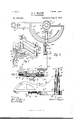
- Figure l is a View in perspective of my improved mitermachine.
- Fig 2 is a top plan view thereof.
- Fig. 3 is a bottomlvie'w.
- Fig. 4 is a front ele' vation, partly in section.
- Fig. 5 is an end view.
- Figli is a sectional view showing one of the guide-posts connected to its bed or base.
- Fig. 7 is a transverse sectional view on the'Y line zr, Fig. 2.
- Fig. 8 is an enlarged View of the scales of graduations.
- Fig. 9 shows one of the saw-guides in different positions.
- A designates tlie base or platform provided at one side with an elongated portion a.
- the front of this base or platform is curved to form a semicircle, and upon its upper surface aretwo scales of graduation a. a', the former scale serving as a guide for'the adjustment on the outer scales
- the numbers of the inner scale extend from the saw-line ninety degrees to right angle, and the numbers of the outerscale back ninety degrees to the forty-iive-degrees line.
- a circular slot or opening a2 adjacent to the inner scale of graduation, while' adjacent to the center of the cord of said base is a second but shorter-curved slot or opening a3.
- B B designate two supporting-posts provided with vertical slots b, extending from their upper down to near their lower ends. These posts have lower reduced ends b', which are threaded and screwed into corresponding holes or openings, one at about the center of Serial No. 399.3.09. (No model.)
- a pin or stud cl,projecting from each post, is inthe path ofV a lug d2 of each saw holder or guide, and thus limits the upward movement of thelatter.
- These lugs cl2 serve as stops toprevent the accidental removal of the saw holder or guide when being raised in the posts.
- Eis a slide-designed to move over the base A and describean arc of a circle, its inner end being coincident with post B.
- This slide consists of a lverti'c'al plate e, having an innerV widened right-angular portion c bearing on said base and an outer elongatedlportion c2 projecting beyond said base. At -its extreme outer end it is' provided witlna right-angular lip or tongue c3, designed to support the block or piece of wood or other articleto be sawed.
- F is a clamp, which consists of fan arm f, havingarear circular end f', throughau opening in which the lower end ofvpost-B is projected, ai boss f2 on said endlpfitting snug against said base around said post.”
- the reduced end c6 of lug or ange e5 is extended through a hole in arm f, and the latter fits snug in a corresponding-.shapedgroove in lug ⁇ or flange c4, its outer end being in Ycontact with a rib f3 on the under-side of base A adjacent the curved edge thereof.
- a threaded rod or screw f4 On the upper projecting end of rod or screw f is a binding nut or arm G, from which projects a vertical flange g, by which the nut orarm can be readily operated, according as it is desired to tighten or loosen the clamp.
- a plate-spring g is secured at g2 to the under side of arm f of said clamp, and its outer free end fits in the slot in the head of screw f, holding the same, as against turning. Hence to loosen or bind the clamp it is only necessary to turn this binding nut or arm.
- the herein described improved mitermachine comprising the base having the sawsupporting posts at one side thereof and provided with curved slots, the slide having lugs extending through said slots, the clamp having a circular-portion encircling one of said posts, the rod or screw connecting said clamp with said slide and having a slot in its lower head, the plate-spring secured to said clamp at one end and having its free end in said slot, and the nut or arm in the upper end of said rod or screw having a vertical flange or projection, substantially as set fort-h.
- the herein-described improved mitermachine comprising the circular base having an arm or elongated portion provided with threaded openings, the slotted posts having reduced threaded ends tting said openings and provided with projecting pins or studs,
- the saw-holders or guides movable in grooves in said slotted posts and having upper overh ancn g portions, the adj nstable screws working in holes in said overhangingportions,and the lugs projecting from said saw-holders or guides and "designed to limit the upward pins or studs, substantiallg7 as set ⁇ forth. ⁇
Landscapes
- Life Sciences & Earth Sciences (AREA)
- Engineering & Computer Science (AREA)
- Mechanical Engineering (AREA)
- Wood Science & Technology (AREA)
- Forests & Forestry (AREA)
- Sawing (AREA)
Description
(No Model.) 2 Sheets-Sheet 1. A. L. MAXIM. MITERIMAGHINAE.
Patented July 5, 1892.
I @QL-wwwa@- gvlwwvd,
2` sheets-sheet 2. A f
(No Model.)
A. L.r MAXIM. MITBR MAUHINB.
Patented July 5, 182g.
vUNIT-ED STATES-@PATENT Genion. f
ABRAHAML. MAXIM, oF OMAHA, NEBRASKA.
-MITER-IMACHINE.
SPECIFICATION forming part of Letters Patent No. 478,449, dated July 5, 1892.
Applicant inea July 1s, 1891.
To all whom, it .may concern:
Be it known that I, ABRAHAM L. MAXIM, a citizen of theUnited States, residing at Omaha, in thecountyy of Douglas and State of Nebraska, have invented a new and useful Miterf Machine, of-which the following is a specifi# cation.
This invention relates to a new and improved miter-machine, and has forits objectthe production of-a device of this nature capable of quick and easy adjustment to any-` angle and `which shall be simpl-e in construction, inexpensive, compact and durable.V
The invention comprises the detail construction, combination, and arrangement ot' parts, substantiallyas hereinafter fully set` forth, and particularly pointed out in the claims.
In the-accompanying drawings, Figure l is a View in perspective of my improved mitermachine. Fig 2 is a top plan view thereof."-
, Fig. 3 is a bottomlvie'w. Fig. 4 is a front ele' vation, partly in section. Fig. 5 is an end view. Figli is a sectional view showing one of the guide-posts connected to its bed or base. Fig. 7 isa transverse sectional view on the'Y line zr, Fig. 2. Fig. 8 is an enlarged View of the scales of graduations. Fig. 9 shows one of the saw-guides in different positions.
Referring to the drawings, A designates tlie base or platform provided at one side with an elongated portion a. The front of this base or platform is curved to form a semicircle, and upon its upper surface aretwo scales of graduation a. a', the former scale serving as a guide for'the adjustment on the outer scales The numbers of the inner scale extend from the saw-line ninety degrees to right angle, and the numbers of the outerscale back ninety degrees to the forty-iive-degrees line. In this base A, adjacent to the inner scale of graduation, is a circular slot or opening a2, while' adjacent to the center of the cord of said base is a second but shorter-curved slot or opening a3.
B B designate two supporting-posts provided with vertical slots b, extending from their upper down to near their lower ends. These posts have lower reduced ends b', which are threaded and screwed into corresponding holes or openings, one at about the center of Serial No. 399.3.09. (No model.)
i the cordel-straight side of the base and the other at the outer end of the elongated portion o of said base; In opposite grooves in these posts are saw holders or guides C, which are providedwith longitudinal slots C', terminating attheirpends in slightlyenlarged openings, saidupper openings serving to form shoulders C2 for the upper thickened portion of the saw-blade X to rest thereon. Through openings Vin overhanging vportions d of lthese saw holdersor guides are adjustable screws D. These screws, by reason of contact with the upper ends of posts B B', serve to limit the downward movement of the saw holders or guides and prevent the saw from descending too far and thus sawing the base, and by being adj ustalole as the saw wears it may be fartherlowered. A pin or stud cl,projecting from each post, is inthe path ofV a lug d2 of each saw holder or guide, and thus limits the upward movement of thelatter. These lugs cl2 serve as stops toprevent the accidental removal of the saw holder or guide when being raised in the posts.
Eis a slide-designed to move over the base A and describean arc of a circle, its inner end being coincident with post B. This slide consists of a lverti'c'al plate e, having an innerV widened right-angular portion c bearing on said base and an outer elongatedlportion c2 projecting beyond said base. At -its extreme outer end it is' provided witlna right-angular lip or tongue c3, designed to support the block or piece of wood or other articleto be sawed. From the under side of the widened portion e project two lugs or flanges@4 c5, which are respectively projected through the slots or openings c2 a3 of base A, said lug or flange e5 being provided with a lower reduced end e6.
F is a clamp, which consists of fan arm f, havingarear circular end f', throughau opening in which the lower end ofvpost-B is projected, ai boss f2 on said endlpfitting snug against said base around said post." The reduced end c6 of lug or ange e5 is extended through a hole in arm f, and the latter fits snug in a corresponding-.shapedgroove in lug `or flange c4, its outer end being in Ycontact with a rib f3 on the under-side of base A adjacent the curved edge thereof. Through coincident holes in arm f, lug c4, base A, and
IOO
widened portion of slide E is passed a threaded rod or screw f4, the head of which is countersunk in the underside of said armf. On the upper projecting end of rod or screw f is a binding nut or arm G, from which projects a vertical flange g, by which the nut orarm can be readily operated, according as it is desired to tighten or loosen the clamp. A plate-spring g is secured at g2 to the under side of arm f of said clamp, and its outer free end fits in the slot in the head of screw f, holding the same, as against turning. Hence to loosen or bind the clamp it is only necessary to turn this binding nut or arm.
From the under side of the elongated portion of slide E project two lugs 72, through coincident holes in which is passed a springpresscd bolt 7L', having an outer headed end 7b2. rlhe inner end of this spring-bolt is designed to enter any one of a series of holes 7a3 in the curved side of base A.
Int practice by placing a bevel to the saw X and slide E the desired degree or inclination will be indicated on the inner scale of graduation on base A, and then by adjusting said slide to the corresponding graduation on the ou-ter scale the initer-cut for the degree first indicated will be obtained.
rlhe advantages of nry improved miter-machine are apparent to those skilled in the art. lit will be especially observed that the same is very simple in construction, is capable of? ready and easy opera-tion, is accurate in its measurements, and is inexpensive.
l claim as my inventionl. lhe herein-described improved miterniachine comprising the base, having the in l movement ot the latter by contact with said ner and outer saw-supporting posts at one side thereof, the slide movable thereover in circular relation to said inner post, the clamp beneath said base provided with an inner circular end surrounding said' inner post and having en gagementwith said slide, and means the binding nut or arm on said rod or screw,
substantially as set forth. t
I 3. The herein described improved mitermachine comprising the base having the sawsupporting posts at one side thereof and provided with curved slots, the slide having lugs extending through said slots, the clamp having a circular-portion encircling one of said posts, the rod or screw connecting said clamp with said slide and having a slot in its lower head, the plate-spring secured to said clamp at one end and having its free end in said slot, and the nut or arm in the upper end of said rod or screw having a vertical flange or projection, substantially as set fort-h.
4. The herein-described improved mitermachine comprising the circular base having an arm or elongated portion provided with threaded openings, the slotted posts having reduced threaded ends tting said openings and provided with projecting pins or studs,
the saw-holders or guides movable in grooves in said slotted posts and having upper overh ancn g portions, the adj nstable screws working in holes in said overhangingportions,and the lugs projecting from said saw-holders or guides and "designed to limit the upward pins or studs, substantiallg7 as set` forth.`
ABRAHAM L. MAXIM. Witnesses:
Ivon L. BRIND, EDWARD D. PA'rToN.
Publications (1)
| Publication Number | Publication Date |
|---|---|
| US478449A true US478449A (en) | 1892-07-05 |
Family
ID=2547304
Family Applications (1)
| Application Number | Title | Priority Date | Filing Date |
|---|---|---|---|
| US478449D Expired - Lifetime US478449A (en) | Miter-machine |
Country Status (1)
| Country | Link |
|---|---|
| US (1) | US478449A (en) |
-
0
- US US478449D patent/US478449A/en not_active Expired - Lifetime
Similar Documents
| Publication | Publication Date | Title |
|---|---|---|
| US415940A (en) | Miter-box | |
| US20080223191A1 (en) | Attachment for a power tool guide rail | |
| US658710A (en) | Apparatus for cutting ovals from cardboard. | |
| US413522A (en) | William a | |
| US816424A (en) | Adjustable fence for saws. | |
| US623156A (en) | humphrey | |
| US1002980A (en) | Miter-box. | |
| US1028529A (en) | Saw-gage. | |
| US221804A (en) | Improvement in gages for circular sawing machines | |
| US369770A (en) | James e | |
| US1026086A (en) | Adjustable miter-box. | |
| US653122A (en) | Metal bench-saw. | |
| US546192A (en) | Paper-holding claivip | |
| US1167254A (en) | Glass-cutting machine. | |
| US414544A (en) | Miter-box | |
| US1316306A (en) | Planograph co | |
| US1050208A (en) | Miter-box. | |
| US622530A (en) | Mitering instrument | |
| US456380A (en) | Guide for saw-benches | |
| US363119A (en) | Mitering-machine | |
| US948428A (en) | Miter-box. | |
| US545895A (en) | Planer-chuck | |
| US760982A (en) | Miter-box. | |
| US795371A (en) | Miter-box. | |
| US384829A (en) | Saw-filing device |