US4780040A - Conveyor guide arrangement - Google Patents
Conveyor guide arrangement Download PDFInfo
- Publication number
- US4780040A US4780040A US07/131,756 US13175687A US4780040A US 4780040 A US4780040 A US 4780040A US 13175687 A US13175687 A US 13175687A US 4780040 A US4780040 A US 4780040A
- Authority
- US
- United States
- Prior art keywords
- guide rail
- chain
- portions
- conveyor
- chains
- Prior art date
- Legal status (The legal status is an assumption and is not a legal conclusion. Google has not performed a legal analysis and makes no representation as to the accuracy of the status listed.)
- Expired - Lifetime
Links
Images


Classifications
-
- B—PERFORMING OPERATIONS; TRANSPORTING
- B65—CONVEYING; PACKING; STORING; HANDLING THIN OR FILAMENTARY MATERIAL
- B65G—TRANSPORT OR STORAGE DEVICES, e.g. CONVEYORS FOR LOADING OR TIPPING, SHOP CONVEYOR SYSTEMS OR PNEUMATIC TUBE CONVEYORS
- B65G23/00—Driving gear for endless conveyors; Belt- or chain-tensioning arrangements
- B65G23/44—Belt or chain tensioning arrangements
-
- H—ELECTRICITY
- H05—ELECTRIC TECHNIQUES NOT OTHERWISE PROVIDED FOR
- H05K—PRINTED CIRCUITS; CASINGS OR CONSTRUCTIONAL DETAILS OF ELECTRIC APPARATUS; MANUFACTURE OF ASSEMBLAGES OF ELECTRICAL COMPONENTS
- H05K13/00—Apparatus or processes specially adapted for manufacturing or adjusting assemblages of electric components
- H05K13/0061—Tools for holding the circuit boards during processing; handling transport of printed circuit boards
Definitions
- the present invention relates to conveyor systems and, more particularly, to conveyor systems which must convey selected items placed thereon from a region of one temperature to a region of a significantly different temperature while supporting such items at edges thereof.
- Conveyors are used for many purposes. Among them is the transporting of items to be heated from an unheated access region into a heating region. In those situations where there is a significant temperature difference between the heating region and the access region, the conveyor is subject to substantial thermal gradients. Such thermal gradients can lead to substantial stresses on the conveyor structural components. The conveyor structural components must be capable of operating in these conditions.
- One kind of conveyor encountering these conditions is a conveyor for supporting the edges of printed circuit boards that are to be conveyed from an access zone into a heating zone for the purpose of causing affixing thereto of electronic components thereon.
- the supporting of these printed circuit boards at edges thereof only permits both sides of the printed circuit board to be heated simultaneously to cause such fixation, or heated alternatively for this purpose in subsequent passes through the heating zone. This capability is desirable in the fabrication of many kinds of printed circuit board systems.
- a conveyor for accomplishing this can be provided by use of a pair of chains which, in one manner or another, support edges of circuit boards between them.
- the chains can then be driven by an actuation means connected to sprockets around which the chains are arrayed.
- the metallic nature of the chains provides a conveying means which can withstand substantial stresses.
- Such chains must each be guided by some kind of a guiding arrangement to permit the chains to move while causing them to stay a selected distance from one another if the printed circuit boards are to be continuously supported at their edges without coming off either chain. Since only a very small portion of the edges of a circuit board will be over each chain, a rather small tolerance in the spacing of one chain from the other is permitted. Thus, the guide rails must set a rather accurate path along which the chains can move.
- a relatively larger but rigid rail is definitely more costly to use than is a rail of a smaller dimensional construction.
- a further difficulty with a relatively large rigid rail is that heating will cause such a rail to expand, and this expansion can lead to the rail bending between its support points on the frame with the result that the rail has a bow in it so that it has a portion with a lateral displacement away from its desired location. Such a displacement will carry the chain with it leading to the possibility of the edge-supported printed circuit boards being carried thereby falling from the chain.
- the present invention provides a conveyor with a frame means and a guide rail for guiding a movable transport member, this guide rail being supported on the frame means with a tension imparting means which applies a tensile force between the ends of the guide rail.
- the same arrangement can be provided with a second substantially parallel guide rail in such a manner that one of them can be allowed to move relatively closer to or further from the other.
- the movable transport member is formed by chains protected by shields in the radiant heating zone into which the conveyor can extend.
- FIG. 1 shows a top view of an embodiment of the present invention
- FIG. 2 shows a cross section view of a portion of FIG. 1,
- FIG. 3 shows a cross section view of a portion of FIG. 1,
- FIG. 4 shows a cross section view alternative to that shown in FIG. 3.
- FIG. 1 shows a partial view from the top of a solder reflow system using radiant, or infrared, heating to cause the reflow of solder paste present on a circuit board, or a component attached to that circuit board, or both.
- the controls for this system, the upper bank of radiant tubes for the heating chamber, details of the drive actuator and other structural details and features are omitted for clarity.
- a dashed-line rectangle outside the structural features shown represents the system outer covering which has also been otherwise omitted for purposes of clarity.
- a conveyor system, 10 is used to transport printed circuit boards, with surface mount electronic components provided thereon, into a heating chamber, 11, where the solder paste provided between the components of the board is reflowed to provide a solder connection between the component terminals and the printed circuit board interconnection system terminals.
- Conveyor system 10 comprises a pair of chains, 12 and 13, which are transporting members, or form the transport member, of conveyor system 10 operating as an edge conveyor. That is, conveyor 10 will support circuit boards being transported only at the edges thereof, thereby leaving both the undersides and the tops of the boards directly exposed to radiant tubes for the purposes of heating in heating chamber 11.
- Each of chains 12 and 13 travel over idler sprockets at the extremes of the chains as shown in FIG. 1.
- Chain 12 goes over an input idler sprocket, 14, and chain 13 goes over an input idler sprocket, 15.
- Chain 12 also goes over an output idler sprocket, 16, while chain 13 additionally goes over another output idler sprocket, 17.
- Chain 12 runs over a stationary guide rail, 18.
- Chain 13 runs over a movable guide rail, 19.
- FIG. 2 represents a broken, cross section view of the structure shown in FIG. 1. That is, only a portion of the structure shown in FIG. 1 is also shown in FIG. 2 with breaks in the structure indicating omitted structure.
- FIG. 2 shows sprockets 15 and 17 at the furthest horizontal extent of chain 13 as described above, and shows therebetween guide rail 19.
- Chain 13 engages two further sprockets, as can be seen in FIG. 2.
- One is a chain tensioning arrangement involving an idler sprocket, 20, having a spring, 21, urging the sprocket in such a manner as to keep tension on the chain as it proceeds to sprocket 15 to keep the chain tight across sprocket 15 and between sprockets 15 and 17.
- the chain is caused to move by an electrical stepper motor (not shown) driving a gear train (not shown) to in turn apply force to a drive sprocket, 22, which causes chain 13 to move in a clockwise direction in FIG. 2.
- chain 13 travels from the conveyor system 10 input near sprocket 15 to the system output near sprocket 17.
- Chain 12 is similarly arranged and driven.
- Guide rails 18 and 19 are each supported by a corresponding pair of levers. As can be seen in FIG. 2, guide rail 19 is supported by an input end lever, 23, and an output end lever, 24.
- Lever 23 can rotate about a pin, 25, serving as a fulcrum.
- Lever 24 can also rotate about a pin, 26, again serving as a fulcrum.
- Fulcrum pin 25 is affixed to a plate structure, 27, to thereby support lever 23, this plate structure also supporting idler sprocket 15.
- Fulcrum pin 26 is affixed to a further plate structure, 28, to thereby support lever 24. Plate structure 28 also supports idler sprocket 17 and the drive shaft on which drive sprocket 22 is fitted.
- Support structure 27 is in turn slidably supported by a channel beam, 29, which is part of the support frame of the solder reflow system.
- structure 28 is slidably supported by another channel beam, 30, which is also part of the support frame of the system.
- the sliding relationship between support structure 27 and frame support 29, and between support structure 28 and frame support 30, permits structures 27 and 28 to slide laterally either way with respect to the direction of conveyance and with respect to frame supports 29 and 30, respectively.
- the entirety of chain 13, guide rail 19, levers 23 and 24, support structures 27 and 28, and the sprockets can move laterally within its range of motion either closer to or farther from chain 12 as indicated by the two double direction arrows in FIG. 1 near sprockets 15 and 17.
- the spacing between chains 12 and 13 can be adjusted to accommodate printed circuit boards of varying widths to achieve supporting these boards at the edges thereof on these chains.
- chain 13, and the strutures associated therewith is accomplished by operating a long screw, 31, through rotating it by rotating a wheel, 32, attached thereto.
- a nut, 33, fixed in structure 27, will move along screw 31 as this screw is turned thereby moving structure 27 with respect to screw 31 and so with respect to frame support 29.
- a drive sprocket, 34, at the end of screw 31 has a chain, 35, arrayed thereover and over a driven sprocket, 36, affixed to the end of another long screw, 37.
- Screw 37 is fitted into a further nut, 38, fixed in structure 28 so that turning of screw 37 causes structure 28 to move with respect to screw 37 and so frame means 30.
- turning wheel 32 causes both screws 31 and 37 to move since moving screw 31 causes chain 35 to rotate screw 37.
- These screw movements cause each of structures 27 and 28 to move with nuts 33 and 38, respectively, which, being fixed therein, move because of the rotating screws.
- the entire arrangement involving chain 13 and guide rail 19 together move either closer to or further from the structure involving chain 12 and guide rail 18.
- Guide rail 19 is shown in FIG. 2 to be connected to input end lever 23 by a link, 39.
- output end lever 24 is connected to guide rail 19 by another link, 40.
- Links 39 and 40 are connected to guide rail 19 and levers 23 and 24, respectively, by pins allowing rotation of these links about the pins.
- levers 23 and 24 are connected to one another through a tensile force providing arrangement.
- This arrangement comprises a pair of threaded rods, 39 and 40, joined by a turnbuckle, 41.
- Threaded rod 39 is joined by a yoke, 42, to lever 23, yoke 42 being able to pivot with respect to lever 23 because of it being joined thereto by a pin.
- Rod 40 is connected by a nut to a plate, 43, as part of a compression spring arrangement, 44.
- Compression spring arrangement 44 has two further plates, 45 and 46, separated by a set of compression springs, 47.
- Plate 46 is connected by bolts, 48, to plate 43 with plate 45 and compression springs 47 located therebetween.
- a further threaded rod, 49 is connected by a nut to plate 45 and passes between springs 47 through plate 46 to be connected by another yoke, 50, to lever 24.
- Yoke 50 is connected to lever 24 such that it can rotate with respect thereto.
- the structure associated with guide rail 18 is essentially the same as that shown in FIG. 2 associated with guide rail 19.
- the use of nuts 33 and 38 in structures 27 and 28, respectively, does not occur in the similar structures associated with chain 12 and guide rail 18 since these are fixed with respect to frame support means 29 and 30, respectively. Rather, screws 31 and 37 pass through these similar structures without interacting with them.
- Each of guide rails 18 and 19 is supported at approximately its end points only, this support provided by the associated pair of input end and output end levers. These levers can supply a considerable tensile force to these guide rails.
- the guide rails will tend to be straight if chosen of a relatively light construction, i.e. small cross-sectional dimensions, to thereby be relatively flexible because such a force will cause the flexible guide rail to seek a position along a straight line between the two force application points at its ends.
- Such a guide rail construction without the application of significant tension, would provide a guide rail which would have a lateral spring constant of a few pounds per inch at most for forces applied perpendicularly to its longitudinal axis.
- the addition of a significant tensile force in the guide rail will provide a much larger effective lateral spring constant. This comes about because of the much greater restoring forces which arise as a result of any lateral deflection of the guide rail due to the large tensile force in the rail acting to keep the rail straight.
- FIG. 2 permits guide rail 19 (and similarly guide rail 18) to expand without any buckling. Such buckling would otherwise occur if the ends of these guide rails were held fixed in position as portions of the interior thereof are brought to 200° C. or more for the purpose of causing the reflow of solder paste used in circuit boards passing thereover.
- Heating chamber 11 has not been shown in FIG. 2 for purposes of clarity, but generally, as can be seen from FIG. 1, much of guide rail 19 and chain 13 thereover will be subjected to such temperatures in heating chamber 11 while the ends of the guide rails will be much closer to the ambient temperature at which the system operates.
- the resulting expansion of guide rail 19 is easily taken up through use of compression spring arrangement 44 which, for the relatively small change in length of guide rail 19 because of this expansion, will continue to provide approximately a constant tension force between yokes 42 and 50.
- guide rails 18 and 19 provide supports for chains 12 and 13, respectively, well adapted for carrying circuit boards supported just at the edges thereof from a room ambient temperature at the system input to the interior of heating chamber 11 and back out after reflow of the solder paste on such boards.
- the use of substantial tensile forces in the guide rails with a thermal expansion accommodation to prevent any significant lateral displacement of portions of the guide rails avoids this result.
- FIG. 2 Further shown in FIG. 2 is a chain guide block, 51, which serves to keep chain 13 engaged with sprocket 15 even though the links in chain 13 may, as a result of heating, be somewhat resistant to rotating with respect to one another to go over sprocket 15. Further supported on block 51 is a rotating wheel, 52, having a shoulder which supports an entering printed circuit board to ease the transition of that board from outside the system onto chain 13. A similar structure is provided with respect to chain 12. Block 51 and roller 52 have been omitted in FIG. 1 for purposes of clarity.
- a further measure is taken to assure good operation of chains 12 and 13 despite their being heated substantially in passing through heating chamber 11.
- Sets of radiation shields, 53 are provided over each so as to shield them from direct radiation by the radiant heating tubes present in the upper bank of heating chamber 11.
- Chains 12 and 13 are shielded from direct radiation due to those radiant heating tubes, 54, provided in the lower bank of heating chamber 11, as shown in FIG. 1, by guide rails 18 and 19
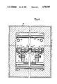
- Heating chamber 11 and radiation shields 53 are better seen in the broken, cross section view of FIG. 3 taken from the partial system view shown in FIG. 1. Portions of chains 12 and 13 and of the tension providing arrangement for guide rails 18 and 19 have been omitted in FIG. 3 for clarity, as have other parts of the system. The drawing has been broken down the middle to narrow it to fit on the drawing sheet.
- Both the upper and lower banks of heating chamber 11 are shown in FIG. 3, and are shown hinged together by hinges, 55, to permit opening heating chamber 11 from the side opposite the hinges.
- Heating chamber 11 is shown to have an outer metallic shell, 56, inside of which is provided a ceramic material, 57, serving as a heat insulator.
- Infrared or radiant heating tubes 54 extend from the sides of insulation 57 and over a portion of insulation 57 in the lower bank of heating chamber 11. Electrical connections for tubes 54 extend through insulation 57, shell 56 and into the control system, none of which has been shown for clarity.
- radiant heating tubes, 58 are present in the upper bank of heating chamber 11 extending between sides of insulation 57 and under a portion thereof.
- radiant heating tubes 54 and 58 extending laterally with respect to the directions of travel of chains 12 and 13 during operation, a further set of radiant heating tubes, 59, extend parallel to these directions of motion between sides of insulating material 57 and under a portion theeof in the upper bank.
- Guide rail 18 is shown in FIG. 3 supporting chain 12 thereon which can be seen to be a roller chain.
- the roller portion of the chain is on the upper surface of guide rail 18 with the chain links extending down past this upper surface to be on either side of guide rail 18 for a distance.
- lateral extensions, 12', in chain 12 are directed toward chain 13, these extensions 12' each having a cylindrial portion conically tapered to another cylindrical portion, the axis of symmetry of these cylinders and the cone portions all being a common axis.
- a similar arrangement of extensions, 13', extending in the opposite direction is provided for chain 13 supported by guide rail 19.
- a portion of a printed circuit board, 60 is shown being conveyed with just its edges supported on the most inward cylindrical portion of extensions 12' and 13' of chains 12 and 13, respectively.
- the conical surface portions of extensions 12' and 13' serve to keep board 60 centered between these conical surfaces during its motion beginning at the conveyor access area at the system input, into and through heating chamber 11, and then out at the system output.
- FIG. 3 A pair of opposing heat shields 53 is shown in FIG. 3 with the left side one of shields 53 being bolted to guide rail 19 at its outer side, and the right side of another heat shield 53 bolted to guide rail 18 also at its outer side.
- Each of shields 53 extends outward and upward from the guide rails to which they are affixed and then over the corresponding chains.
- right side heat shield 53 has a portion over the upper surfaces of chain 12
- left side heat shield 53 has a portion extending over the upper surfaces of chain 13.
- a similar mounting arrangement occurs for each heat shield 53 shown in FIG. 1.
- shields are provided to reduce the heating of chains 12 and 13 in conveyor 10 and the guide rails on which they are supported by, as indicated, blocking direct radiation from radiant tubes 58 to these chains and guide rails.
- FIG. 1 there are four shields 53 over each of chains 12 and 13. They are broken into sections along each guide rail to avoid having them subjected to the same risk of buckling because of the heat generated in heating chamber 11.
- shields 53 are bolted with relatively little compressive force so that they are able to slide under the bolts as they expand and contract due to the heating and cooling thereof during and after system operation.
- a nozzle means, 61 which is supplied with a cooling gas, typically air, from an input manifold, 62, shown in FIG. 1.
- Manifold 62 can be connected to a source of gas, such as air, which is under a pressure greater than that of the ambient conditions in which the system operates. This provides the opportunity to cool the lower side of a board 60 as it passes through heating chamber 11 while radiantly heating the upper side thereof by infrareed radiation from radiant tubes 58. Such a capability is desired in some situations in the mounting of electronic components of some kinds on circuit boards.
- a bank of fans, 63 is shown positioned toward the end of conveyor 10 near the output of the system in FIG. 3.
- Fans 63 provide a strong cooling gas flow to rapidly cool circuit boards 60 after they emerge from heating chamber 11.
- FIG. 4 shows a chain and heat shield arrangement alternative to that shown in FIG. 3.
- extension, 12" and 13" of chains 12 and 13 are provided on the opposite side of the extensions 12' and 13' of each of the board carrying chains now redesignated 12A and 13A.
- Extensions 13" and 13" have rollers, 64 and 65, mounted thereon so that the weight of circuit board 60 will at most cause rollers 64 and 65 to swing up and run against the upper portions of the heat shields now redesignated as 53'.
- This arrangement will reduce wear on the links which can occur in the arrrangement of FIG. 3 to the extent these links tend to rub against the upper edges of heat shields 53.
Abstract
Description
Claims (20)
Priority Applications (2)
| Application Number | Priority Date | Filing Date | Title |
|---|---|---|---|
| US07/131,756 US4780040A (en) | 1987-12-11 | 1987-12-11 | Conveyor guide arrangement |
| PCT/US1988/004405 WO1989005272A1 (en) | 1987-12-11 | 1988-12-08 | Conveyor guide arrangement |
Applications Claiming Priority (1)
| Application Number | Priority Date | Filing Date | Title |
|---|---|---|---|
| US07/131,756 US4780040A (en) | 1987-12-11 | 1987-12-11 | Conveyor guide arrangement |
Publications (1)
| Publication Number | Publication Date |
|---|---|
| US4780040A true US4780040A (en) | 1988-10-25 |
Family
ID=22450882
Family Applications (1)
| Application Number | Title | Priority Date | Filing Date |
|---|---|---|---|
| US07/131,756 Expired - Lifetime US4780040A (en) | 1987-12-11 | 1987-12-11 | Conveyor guide arrangement |
Country Status (2)
| Country | Link |
|---|---|
| US (1) | US4780040A (en) |
| WO (1) | WO1989005272A1 (en) |
Cited By (14)
| Publication number | Priority date | Publication date | Assignee | Title |
|---|---|---|---|---|
| US5450946A (en) * | 1993-05-04 | 1995-09-19 | Stiwa-Fertigungstechnik Sticht Gesellschaft M.B.H. | Installation for processing and/or assembling components |
| US5475969A (en) * | 1991-11-19 | 1995-12-19 | Mcneil-Ppc, Inc. | System for applying a heat-shrinkable sleeve to a container |
| US5566816A (en) * | 1994-10-11 | 1996-10-22 | Illinois Tool Works Inc. | Conveying and centering apparatus |
| US5791453A (en) * | 1995-08-29 | 1998-08-11 | Soltec B.V. | Transporting device with fixation finger |
| US6213462B1 (en) * | 1998-06-26 | 2001-04-10 | Heidelberger Druckmaschinen Aktiengesellschaft | Chain conveyor for a sheet-processing printing machine; and a printing machine having the chain conveyor |
| US6533577B2 (en) | 2001-02-02 | 2003-03-18 | Cvd Equipment Corporation | Compartmentalized oven |
| US20030230468A1 (en) * | 2002-06-15 | 2003-12-18 | Uh Ji Heum | Conveyor for liquid crystal panel |
| US7225917B2 (en) * | 2002-06-15 | 2007-06-05 | Lg.Philips Lcd Co., Ltd. | Conveyor system having width adjustment unit |
| US20100000387A1 (en) * | 2008-07-02 | 2010-01-07 | Thacker Thomas M | Guide bar track extension method and apparatus |
| US20140133940A1 (en) * | 2012-04-04 | 2014-05-15 | Victor Chun | Rail System for Thermoformer with Dual Motor Chain Drive |
| US20150163970A1 (en) * | 2013-12-09 | 2015-06-11 | Wistron Corporation | Electronic component removal apparatus for a circuit board |
| US20160296987A1 (en) * | 2013-11-22 | 2016-10-13 | Danieli & C. Officine Meccaniche Spa | Drawing assembly for drawing machines, provided with intermediate chains, and method for tensioning said intermediate chains |
| US9656811B2 (en) * | 2015-10-13 | 2017-05-23 | Weller, Inc. | Drag slat chain tensioning device and stop |
| US10124960B2 (en) * | 2015-02-05 | 2018-11-13 | Rexnord Flattop Europe B.V. | Chain conveyor with adjustable distance between shafts |
Citations (17)
| Publication number | Priority date | Publication date | Assignee | Title |
|---|---|---|---|---|
| US675281A (en) * | 1899-09-18 | 1901-05-28 | Arthur W Johnson | Heating and roasting furnace. |
| US964191A (en) * | 1909-05-15 | 1910-07-12 | Lawrence C Steele | Heating-furnace for sheet metal. |
| US1151355A (en) * | 1915-01-14 | 1915-08-24 | Gottschalk Automatic Brick Oven Company Inc | Dough container for baking hearth-bread in automatic ovens. |
| US2975885A (en) * | 1959-10-30 | 1961-03-21 | Mercury Hendling Systems Inc | Office conveyor |
| US3391658A (en) * | 1967-08-10 | 1968-07-09 | Robert W. Williams | Self-adjusting holddown device |
| US3857478A (en) * | 1969-09-17 | 1974-12-31 | Nielsen & Son Maskinfab As H | System of and a method for transporting heavy or bulky articles |
| US3965523A (en) * | 1974-09-16 | 1976-06-29 | J. P. Elliott Associates, Inc. | Bearing washer |
| US4030595A (en) * | 1968-11-14 | 1977-06-21 | Molins Machine Company, Limited | Laterally flexible conveyor construction |
| US4062459A (en) * | 1975-12-31 | 1977-12-13 | Harper Electric Furnace Corporation | Conveyor for heat treating furnace |
| US4253343A (en) * | 1979-07-10 | 1981-03-03 | Deere & Company | Belt drive system with adjustably gauged tightener means |
| US4269303A (en) * | 1975-08-04 | 1981-05-26 | Cornell Cyrus J | Wood conveyor apparatus |
| US4311458A (en) * | 1979-07-19 | 1982-01-19 | Caratsch Hans Peter | Tunnel furnace for fabricating plate-like flat structures, especially printed circuit boards coated at both sides with a curable material |
| US4353459A (en) * | 1980-02-28 | 1982-10-12 | Rexnord Inc. | Conveyor chain |
| US4505692A (en) * | 1982-02-19 | 1985-03-19 | Mannesmann Aktiengesellschaft | Traction device for buffering tubes |
| US4558779A (en) * | 1982-10-13 | 1985-12-17 | Rovema Verpackungsmaschinen Gmbh | Conveyor apparatus, in particular for use in packaging plants |
| US4582972A (en) * | 1984-08-22 | 1986-04-15 | General Motors Corporation | Chain feed mechanism for an induction heating furnace |
| US4613278A (en) * | 1982-09-09 | 1986-09-23 | Alfred Bilsing | Conveyor robot |
-
1987
- 1987-12-11 US US07/131,756 patent/US4780040A/en not_active Expired - Lifetime
-
1988
- 1988-12-08 WO PCT/US1988/004405 patent/WO1989005272A1/en unknown
Patent Citations (17)
| Publication number | Priority date | Publication date | Assignee | Title |
|---|---|---|---|---|
| US675281A (en) * | 1899-09-18 | 1901-05-28 | Arthur W Johnson | Heating and roasting furnace. |
| US964191A (en) * | 1909-05-15 | 1910-07-12 | Lawrence C Steele | Heating-furnace for sheet metal. |
| US1151355A (en) * | 1915-01-14 | 1915-08-24 | Gottschalk Automatic Brick Oven Company Inc | Dough container for baking hearth-bread in automatic ovens. |
| US2975885A (en) * | 1959-10-30 | 1961-03-21 | Mercury Hendling Systems Inc | Office conveyor |
| US3391658A (en) * | 1967-08-10 | 1968-07-09 | Robert W. Williams | Self-adjusting holddown device |
| US4030595A (en) * | 1968-11-14 | 1977-06-21 | Molins Machine Company, Limited | Laterally flexible conveyor construction |
| US3857478A (en) * | 1969-09-17 | 1974-12-31 | Nielsen & Son Maskinfab As H | System of and a method for transporting heavy or bulky articles |
| US3965523A (en) * | 1974-09-16 | 1976-06-29 | J. P. Elliott Associates, Inc. | Bearing washer |
| US4269303A (en) * | 1975-08-04 | 1981-05-26 | Cornell Cyrus J | Wood conveyor apparatus |
| US4062459A (en) * | 1975-12-31 | 1977-12-13 | Harper Electric Furnace Corporation | Conveyor for heat treating furnace |
| US4253343A (en) * | 1979-07-10 | 1981-03-03 | Deere & Company | Belt drive system with adjustably gauged tightener means |
| US4311458A (en) * | 1979-07-19 | 1982-01-19 | Caratsch Hans Peter | Tunnel furnace for fabricating plate-like flat structures, especially printed circuit boards coated at both sides with a curable material |
| US4353459A (en) * | 1980-02-28 | 1982-10-12 | Rexnord Inc. | Conveyor chain |
| US4505692A (en) * | 1982-02-19 | 1985-03-19 | Mannesmann Aktiengesellschaft | Traction device for buffering tubes |
| US4613278A (en) * | 1982-09-09 | 1986-09-23 | Alfred Bilsing | Conveyor robot |
| US4558779A (en) * | 1982-10-13 | 1985-12-17 | Rovema Verpackungsmaschinen Gmbh | Conveyor apparatus, in particular for use in packaging plants |
| US4582972A (en) * | 1984-08-22 | 1986-04-15 | General Motors Corporation | Chain feed mechanism for an induction heating furnace |
Cited By (22)
| Publication number | Priority date | Publication date | Assignee | Title |
|---|---|---|---|---|
| US5475969A (en) * | 1991-11-19 | 1995-12-19 | Mcneil-Ppc, Inc. | System for applying a heat-shrinkable sleeve to a container |
| US5628847A (en) * | 1991-11-19 | 1997-05-13 | Mcneil-Ppc, Inc. | System for applying a heat-shrinkable sleeve to a container |
| US5450946A (en) * | 1993-05-04 | 1995-09-19 | Stiwa-Fertigungstechnik Sticht Gesellschaft M.B.H. | Installation for processing and/or assembling components |
| GB2277728B (en) * | 1993-05-04 | 1996-12-18 | Sticht Fertigungstech Stiwa | Installation for processing and/or assembling components |
| US5566816A (en) * | 1994-10-11 | 1996-10-22 | Illinois Tool Works Inc. | Conveying and centering apparatus |
| US5791453A (en) * | 1995-08-29 | 1998-08-11 | Soltec B.V. | Transporting device with fixation finger |
| US6213462B1 (en) * | 1998-06-26 | 2001-04-10 | Heidelberger Druckmaschinen Aktiengesellschaft | Chain conveyor for a sheet-processing printing machine; and a printing machine having the chain conveyor |
| US6533577B2 (en) | 2001-02-02 | 2003-03-18 | Cvd Equipment Corporation | Compartmentalized oven |
| US20030230468A1 (en) * | 2002-06-15 | 2003-12-18 | Uh Ji Heum | Conveyor for liquid crystal panel |
| US7225917B2 (en) * | 2002-06-15 | 2007-06-05 | Lg.Philips Lcd Co., Ltd. | Conveyor system having width adjustment unit |
| US20100000387A1 (en) * | 2008-07-02 | 2010-01-07 | Thacker Thomas M | Guide bar track extension method and apparatus |
| US8375835B2 (en) | 2008-07-02 | 2013-02-19 | Thomas M. Thacker | Guide bar track extension method and apparatus |
| US20140133940A1 (en) * | 2012-04-04 | 2014-05-15 | Victor Chun | Rail System for Thermoformer with Dual Motor Chain Drive |
| US9079718B2 (en) * | 2012-04-04 | 2015-07-14 | Brown Machine, Llc | Rail system for thermoformer with dual motor chain drive |
| US20160296987A1 (en) * | 2013-11-22 | 2016-10-13 | Danieli & C. Officine Meccaniche Spa | Drawing assembly for drawing machines, provided with intermediate chains, and method for tensioning said intermediate chains |
| US10449585B2 (en) * | 2013-11-22 | 2019-10-22 | Danieli & C. Officine Meccaniche S.P.A. | Drawing assembly for drawing machines, provided with intermediate chains, and method for tensioning said intermediate chains |
| US20150163970A1 (en) * | 2013-12-09 | 2015-06-11 | Wistron Corporation | Electronic component removal apparatus for a circuit board |
| US9585295B2 (en) * | 2013-12-09 | 2017-02-28 | Wistron Corporation | Electronic component removal apparatus for a circuit board |
| US10124960B2 (en) * | 2015-02-05 | 2018-11-13 | Rexnord Flattop Europe B.V. | Chain conveyor with adjustable distance between shafts |
| US9656811B2 (en) * | 2015-10-13 | 2017-05-23 | Weller, Inc. | Drag slat chain tensioning device and stop |
| US20170183164A1 (en) * | 2015-10-13 | 2017-06-29 | Weiler, Inc. | Drag Slat Chain Tensioning Device and Stop |
| US9896272B2 (en) * | 2015-10-13 | 2018-02-20 | Weiler | Drag slat chain tensioning device and stop |
Also Published As
| Publication number | Publication date |
|---|---|
| WO1989005272A1 (en) | 1989-06-15 |
Similar Documents
| Publication | Publication Date | Title |
|---|---|---|
| US4780040A (en) | Conveyor guide arrangement | |
| US5871325A (en) | Thin support for PC board transfer system | |
| CN101264665B (en) | Stretcher for sheet-like substance | |
| US3934970A (en) | Glass tempering system | |
| US6997307B2 (en) | Device for tensioning and loosening of an endless conveyor belt which is guided over deflection means | |
| US4997364A (en) | Furnace assembly for reflowing solder on printed circuit boards | |
| AU2005248980A1 (en) | Apparatus for conveying coils of metal strip on pallets | |
| FI57395C (en) | FOERFARANDE OCH ANORDNING FOER UPPVAERMNING AV EN GLASSKIVA | |
| US7316308B2 (en) | Supporting device of a transport device of a soldering apparatus | |
| US4341546A (en) | Roll drive mechanism for glass sheet processing equipment | |
| KR950004528B1 (en) | Apparatus for pulling forward or holding back moving metal strips | |
| KR101922902B1 (en) | Reflow Soldering Machine Having Droop Prevention Structure For Circuit Board | |
| US2685374A (en) | Sheet transposing apparatus | |
| US4973243A (en) | Heating system in the manufacture of printed circuit boards, assemblies and the like | |
| US4074382A (en) | Heating apparatus for book forming and creasing irons | |
| JPH02247490A (en) | Continuous furance | |
| US4825538A (en) | Method and apparatus for inserting pins into holes in perforate board members | |
| US4973244A (en) | Heating system in the manufacture of printed circuit boards, assemblies and the like | |
| CZ50296A3 (en) | Device for shifting treated parts through a sequence of treatment stations | |
| JPH079846Y2 (en) | Guide rail mounting structure for transport mechanism | |
| JPH0645747A (en) | Reflow device | |
| JPH01117117A (en) | Printed board conveyor for automatic solderer | |
| JP2682085B2 (en) | Reflow soldering equipment | |
| JP2001345551A (en) | Board carriage mechanism in reflow-soldering apparatus | |
| US4784309A (en) | Soldering machine with cooled guide profiles |
Legal Events
| Date | Code | Title | Description |
|---|---|---|---|
| AS | Assignment |
Owner name: RESEARCH, INCORPORATED, EDEN PRAIRIE, MINNESOTA A Free format text: ASSIGNMENT OF ASSIGNORS INTEREST.;ASSIGNOR:PETERSEN, PAUL S.;REEL/FRAME:004807/0513 Effective date: 19871211 Owner name: RESEARCH, INCORPORATED, EDEN PRAIRIE, MINNESOTA A Free format text: ASSIGNMENT OF ASSIGNORS INTEREST;ASSIGNOR:PETERSEN, PAUL S.;REEL/FRAME:004807/0513 Effective date: 19871211 |
|
| FEPP | Fee payment procedure |
Free format text: PAT HOLDER CLAIMS SMALL ENTITY STATUS - SMALL BUSINESS (ORIGINAL EVENT CODE: SM02); ENTITY STATUS OF PATENT OWNER: SMALL ENTITY Free format text: PAYOR NUMBER ASSIGNED (ORIGINAL EVENT CODE: ASPN); ENTITY STATUS OF PATENT OWNER: SMALL ENTITY |
|
| FPAY | Fee payment |
Year of fee payment: 4 |
|
| FPAY | Fee payment |
Year of fee payment: 8 |
|
| AS | Assignment |
Owner name: COAST BUSINESS CREDIT, A DIVISION OF SOUTHERN PACI Free format text: ASSIGNMENT OF ASSIGNORS INTEREST;ASSIGNOR:RESEARCH, INCORPORATED, A CORP. OF MINNESOTA;REEL/FRAME:009737/0451 Effective date: 19981217 |
|
| REMI | Maintenance fee reminder mailed | ||
| FEPP | Fee payment procedure |
Free format text: PETITION RELATED TO MAINTENANCE FEES GRANTED (ORIGINAL EVENT CODE: PMFG); ENTITY STATUS OF PATENT OWNER: SMALL ENTITY |
|
| FP | Lapsed due to failure to pay maintenance fee |
Effective date: 20001025 |
|
| SULP | Surcharge for late payment | ||
| AS | Assignment |
Owner name: KINNEY & LANGE, P.A., MINNESOTA Free format text: ATTORNEY LIEN PURSUANT TO MINN. STAT.;ASSIGNOR:RESEARCH, INCORPORATED;REEL/FRAME:012083/0544 Effective date: 20010815 |
|
| STCF | Information on status: patent grant |
Free format text: PATENTED CASE |
|
| PRDP | Patent reinstated due to the acceptance of a late maintenance fee |
Effective date: 20010824 |
|
| AS | Assignment |
Owner name: KINNEY & LANGE, P.A., MINNESOTA Free format text: RELEASE OF ATTORNEY'S LIEN;ASSIGNOR:RESEARCH, INCORPORATED;REEL/FRAME:012454/0159 Effective date: 20011024 |
|
| AS | Assignment |
Owner name: MANCHESTER COMMERCIAL FINANCE, LLC, MINNESOTA Free format text: SECURITY INTEREST;ASSIGNOR:RESEARCH INCORPORATED;REEL/FRAME:012698/0457 Effective date: 20020214 |
|
| AS | Assignment |
Owner name: CVD EQUIPMENT CORPORATION, NEW YORK Free format text: ASSIGNMENT OF ASSIGNORS INTEREST;ASSIGNOR:RESEARCH INCORPORATED;REEL/FRAME:012906/0079 Effective date: 20011009 |