US4772336A - Method of improving residual stress in circumferential weld zone - Google Patents

Method of improving residual stress in circumferential weld zone Download PDF

Info

Publication number
US4772336A
US4772336A US07/015,624 US1562487A US4772336A US 4772336 A US4772336 A US 4772336A US 1562487 A US1562487 A US 1562487A US 4772336 A US4772336 A US 4772336A
Authority
US
United States
Prior art keywords
cylinder
weld zone
residual stress
stress
cylinders
Prior art date
Legal status (The legal status is an assumption and is not a legal conclusion. Google has not performed a legal analysis and makes no representation as to the accuracy of the status listed.)
Expired - Lifetime
Application number
US07/015,624
Inventor
Kunio Enomoto
Tasuku Shimizu
Shinji Sakata
Terunobu Koike
Nobuo Shimizu
Tsukasa Ikegami
Current Assignee (The listed assignees may be inaccurate. Google has not performed a legal analysis and makes no representation or warranty as to the accuracy of the list.)
Hitachi Ltd
Original Assignee
Hitachi Ltd
Priority date (The priority date is an assumption and is not a legal conclusion. Google has not performed a legal analysis and makes no representation as to the accuracy of the date listed.)
Filing date
Publication date
Application filed by Hitachi Ltd filed Critical Hitachi Ltd
Assigned to HITACHI, LTD., A CORP OF JAPAN reassignment HITACHI, LTD., A CORP OF JAPAN ASSIGNMENT OF ASSIGNORS INTEREST. Assignors: ENOMOTO, KUNIO, IKEGAMI, TSUKASA, KOIKE, TERUNOBU, SAKATA, SHINJI, SHIMIZU, NOBUO, SHIMIZU, TASUKU
Application granted granted Critical
Publication of US4772336A publication Critical patent/US4772336A/en
Anticipated expiration legal-status Critical
Expired - Lifetime legal-status Critical Current

Links

Images

Classifications

    • CCHEMISTRY; METALLURGY
    • C21METALLURGY OF IRON
    • C21DMODIFYING THE PHYSICAL STRUCTURE OF FERROUS METALS; GENERAL DEVICES FOR HEAT TREATMENT OF FERROUS OR NON-FERROUS METALS OR ALLOYS; MAKING METAL MALLEABLE, e.g. BY DECARBURISATION OR TEMPERING
    • C21D9/00Heat treatment, e.g. annealing, hardening, quenching or tempering, adapted for particular articles; Furnaces therefor
    • C21D9/50Heat treatment, e.g. annealing, hardening, quenching or tempering, adapted for particular articles; Furnaces therefor for welded joints

Definitions

  • the present invention relates to a method of improving tensile residual stress in a circumferential weld zone for connecting a piping or in a circumferential weld zone of a cylindrical vessel and, more particularly, to a method of improving residual stress in a circumferential weld zone of two members one of which has a high rigidity.
  • tensile residual stress in the order of yield stress of the material being used exists in the inner and outer surfaces of weld zone, with the tensile residual stress causing fatigue failure, stress corrosion or the like to the weld zone of the vessel or piping depending on the condition in use of the apparatus, resulting in a low availability factor of the apparatus.
  • the stress corrosion cracking caused in the weld zone of piping of a stainless steel SUS 304 in the primary cooling system piping of a nuclear power generation plant with boiling water reactor is typically susceptible to tension residual stress resulting in decreasing the availability factor of power generation plant.
  • various studies have been made to develop methods for reducing the tensile residual stress in the weld zone of piping.
  • a stress-improving method using a high-frequency induction heating was developed as a counter measure method for an already existing and operating plant and has been used in many actual plants.
  • This method comprises the steps of providing around the outer periphery of the annular circumferential weld zone of pipes a high-frequency induction heating coil for local heating, and rapidly heating the weld zone through a high-frequency induction heating device and a cable while cooling the inner surface of pipes by a coolant.
  • a tensile stress occurs in the inner surface due to the heating, and when a temperature differential between the inner and outer surfaces of piping is about 200° C., a tensile yield occurs in the inner surface thereby causing a tensile permanent set.
  • a compressive stress occurs corresponding to the tensile permanent set brought about by the heating. Namely, the residual stress in the inner surface of the pipe which was at a tensile stress before being heated can be relieved.
  • an object of the invention resides in providing a method of improving the residual stress, which can relieve the tensile residual stress in a circumferential weld zone between two members one of which was a higher rigidity than the other, and efficiently using stress distribution characteristics in a local bending deformation.
  • Another object of the invention resides providing a method of improving residual stress, which can enhance the strength against cracking and the strength against crack development in apparatus and pipe system which are used in a corrosive environment and under an action of a static or dynamic, outer load.
  • FIGS. 1 and 2 are partial longitudinal cross-sectional views of prior art construction
  • FIG. 3a is a partial cross-sectional view of a construction similar to FIG. 2 for detecting the residual stress distributions due to welding;
  • FIG. 3b is a graphical illustration of the actual residual stress distributions
  • FIG. 4a is an a partial cross-sectional view depicting a case where a conventional method is applied to the weld zone shown in FIG. 3a;
  • FIG. 4b is a graphical illustration of residual stress distributions showing the result of the stress-improving treatment conducted in accordance with the method of FIG. 4a;
  • FIG. 5 is a partial cross-secional view of the basic concept of the method of the invention.
  • FIG. 6 is a cross-sectional view taken along the central portion of the pipe shown in FIG. 5;
  • FIG. 7 is a graphical illustration of the stress distributions in the inner surface of the pipe shown in FIG. 5 along the length thereof;
  • FIG. 8 is a graphical illustration depicting the behavior between stress and strain, for explaining the effect of the invention.
  • FIG. 9a is a partial cross-sectional view of an embodiment of the invention.
  • FIGS. 9b to 9d are graphical illustrations of the effects of the embodiment shown in FIG. 9a;
  • FIG. 10 is a partial cross-sectional view of an example of the application of the invention.
  • FIG. 11 is a partial cross-sectional view of a modified embodiment of the invention.
  • FIG. 12 is a schematic detail of deformation preventing clamp used in the embodiment of FIG. 11.
  • stress-improving method using a high-frequency induction heating comprises the steps of providing, around the outer periphery of the annular circumferential weld zone 2 of pipes 1b and 1b, a high-frequency induction heating coil 3 for local heating and rapidly heating the weld zone through a high-frequency induction heating device 5 and a cable 6 while cooling the inner surface of pipes 1a and 1b by a coolant 4.
  • a temperature differential occurs in the direction of wall thickness so that the temperature at the outer surface of the weld zone is high and, at the inner surface of the same is low.
  • a tensile stress occurs in the inner surface due to the heating, and, when the temperature difference between the inner and outer surfaces of piping is in the order of 200° C., a tensile yield occurs in the inner surface thereby causing a tensile permanent set.
  • a compressive stress occurs corresponding to the tensile permanent set brought about by the heating. Namely, the residual stress in the inner surface of the pipe which was at a tensile stress before being heated, can be relieved.
  • the stress improvement in the inner surface can not be obtained.
  • the weld zone 2 is rapidly heated to about 500° C. at its outer surface, resulting in a relieving of the tensile residual stress as shown in FIG. 4b, but not achieving a remarkable improving effect.
  • the residual stress in weld zone 2 can not be sufficiently relieved by the conventional method.
  • FIGS. 5 and 6 when outwardly concentrated loads are radially applied to the cross-section of a hollow cylinder, a local expanding deformation is caused in the inner surface of the hollow cylinder and local bending stress distribution such as shown in FIG. 7 occur therein.
  • a compressive stress occurs in the region A of
  • a tensile stress occurs in the region B of 2 ⁇
  • the solid line represents the strain distribution
  • the dotted line represents the stress distribution in the inner surface which is schematically shown in FIG. 8.
  • the hysteretic route 0 ⁇ ⁇ 1 ⁇ ⁇ 2 ⁇ ⁇ 3 represents a behavior of the region A in which, by the load, a compressive stress is applied thereby causing the compressive yield ⁇ 1 and the compressive plastic strain ⁇ 2 and then the compressive stress decreases as the load is removed and when the load is completely removed the tensile stress ⁇ 3 remains.
  • the hysteretic route 0 ⁇ ⁇ 1' ⁇ ⁇ 2' ⁇ ⁇ 3' represents a behavior of the region B in which by the load a tensile stress is applied thereby causing the tensile yield ⁇ 1' and the tensile plastic strain ⁇ 2' and then the tensile stress decreases as the load is removed and when the load is completely removed the compressive stress ⁇ 3' remains.
  • the tensile residual stress ⁇ 2' occurs by a small load because in the region B the state ⁇ 1' exists at the start of application of load, and when the load is removed the state ⁇ 3' occurs, so that it is possible to improve the tensile residual stress state ⁇ 1' to the compressive residual stress state ⁇ 3' by the small load.
  • FIG. 9a provides an illustrated example of an embodiment of the invention applied to a circumferential weld zone between a tube plate 7 a shell 8 of a heat exchanger.
  • the coil 3 is energized by a high-frequency induction heating device 5 through cable 6.
  • the coil 3 is excited by a high-frequency current so that a high-frequency current is induced in the portion of the shell 8 covered by the coil 3 to heat this portion of the shell, while the inner surface is cooled by a coolant such as still water, flowing water, sprayed water and the like. Since the inner surface is cooled so that a temperature differential occurs in the wall thickness, and an expanding deformation approximately corresponding to a average temperature is caused in the portion of shell covered by the coil thereby causing a local bending action in the vicinity of each axial end of the coil 3, so that the effect mentioned in the foregoing paragraph can be obtained.
  • a coolant such as still water, flowing water, sprayed water and the like.
  • FIG. 9b shows the residual stress distributions in the inner surface when the shell is heated until the average temperature in the wall thickness of fthe shell covered by the coil 3 becomes 350° C.
  • FIG. 9c shows a general tendency of the residual stress distribution when the distance Hc between the tube plate's end face (a portion where the rigidity drastically changes from a high level to a low level) and the axial end of the coil 3 has been made large, and represents a fact that when the distance Hc is too large the tensile residual stress occurs in the vicinity of the end of the tube plate face, so that it becomes harmful.
  • Hq is a point at which the stress changes from tensile stress to compressive stress
  • Hg is a point at which the stress reversely changes from compressive stress to tensile stress
  • Hr and Hs are points at which the compressive stress starts to become lower than -5 Kgf/mm 2 and higher than -5 Kgf/mm 2 , respectively.
  • the parameters are represented, in FIG. 9d, on the axis of odinate in terms of (Hp, Hq, Hr, Hs)/ ⁇ Rt and the coil position Hc is represented on the axis of abscissa in terms of Hc/ ⁇ Rt.
  • the invention can be applied not only to the case where the rigidities of two members to be welded are extremely different as in the circumferential weld zone 2 between the tube plate 7 and the shell 8 but also to the circumferential weld zone 2 between a nozzle 9 and a pipe 1 as shown in FIG. 10.
  • FIG. 11 shows the deformation preventing clamp in its as-detached state. Hydraulic cylinders may be provided in place of the clamping bolts.
  • the advantage of the detachable clamp 12 resides in the fact that, by threadably attaching the clamping bolts 11a to 11h, a tensile stress occurs in the inner surface of weld zone 2 and it is possible, in cooperation with the local bending action brought about by heating with the coil 3, to enhance the effect of improving the residual stress to the compressive residual stress.
  • the high-frequency heating with cooling of the inner surface is utilized as a means for imparting the local expanding deformation, but even if the cooling is omitted the present invention can nevertheless improve a reduction in the tensile residual stress due to welding.

Landscapes

  • Chemical & Material Sciences (AREA)
  • Engineering & Computer Science (AREA)
  • Physics & Mathematics (AREA)
  • Thermal Sciences (AREA)
  • Crystallography & Structural Chemistry (AREA)
  • Mechanical Engineering (AREA)
  • Materials Engineering (AREA)
  • Metallurgy (AREA)
  • Organic Chemistry (AREA)
  • Heat Treatment Of Articles (AREA)

Abstract

A method for improving residual stress in a circumferential weld zone of a piping and the like which includes preventing deformation of the weld zone, and causing a local expansion or contraction of a portion of the piping axially spaced from the weld zone thereby effecting a plastic working so as to increase or decrease the diameter of piping. The method can effectively be applied to apparatus and pipe system which are used in a corrosive environment and under action of a static or dynamic outer load.

Description

This is a continuation of application Ser. No. 658,170, filed Oct. 5, 1984, abandoned.
BACKGROUND OF THE INVENTION
The present invention relates to a method of improving tensile residual stress in a circumferential weld zone for connecting a piping or in a circumferential weld zone of a cylindrical vessel and, more particularly, to a method of improving residual stress in a circumferential weld zone of two members one of which has a high rigidity.
Generally, tensile residual stress in the order of yield stress of the material being used exists in the inner and outer surfaces of weld zone, with the tensile residual stress causing fatigue failure, stress corrosion or the like to the weld zone of the vessel or piping depending on the condition in use of the apparatus, resulting in a low availability factor of the apparatus. The stress corrosion cracking caused in the weld zone of piping of a stainless steel SUS 304 in the primary cooling system piping of a nuclear power generation plant with boiling water reactor is typically susceptible to tension residual stress resulting in decreasing the availability factor of power generation plant. In order to prevent stress corrosion cracking, various studies have been made to develop methods for reducing the tensile residual stress in the weld zone of piping. As a result, a stress-improving method using a high-frequency induction heating was developed as a counter measure method for an already existing and operating plant and has been used in many actual plants. This method comprises the steps of providing around the outer periphery of the annular circumferential weld zone of pipes a high-frequency induction heating coil for local heating, and rapidly heating the weld zone through a high-frequency induction heating device and a cable while cooling the inner surface of pipes by a coolant. By this rapid heating, such a temperature difference occurs in the direction of wall thickness that the temperature at the outer surface of the weld zone becomes high and that at the inner surface of the same becomes low. Consequently, a tensile stress occurs in the inner surface due to the heating, and when a temperature differential between the inner and outer surfaces of piping is about 200° C., a tensile yield occurs in the inner surface thereby causing a tensile permanent set. When the heating treatment is finished and the temperature differential between the inner and outer surfaces is zero, a compressive stress occurs corresponding to the tensile permanent set brought about by the heating. Namely, the residual stress in the inner surface of the pipe which was at a tensile stress before being heated can be relieved.
However, in the case where one of two members in the circumferential weld zone has a higher rigidity than the other, the stress improvement in the inner surface cannot be obtained.
Accordingly, an object of the invention resides in providing a method of improving the residual stress, which can relieve the tensile residual stress in a circumferential weld zone between two members one of which was a higher rigidity than the other, and efficiently using stress distribution characteristics in a local bending deformation.
Another object of the invention resides providing a method of improving residual stress, which can enhance the strength against cracking and the strength against crack development in apparatus and pipe system which are used in a corrosive environment and under an action of a static or dynamic, outer load.
According to advantageous features of the invention, when outwardly concentrated loads are radially applied to the cross-section of a hollow cylinder, a local expanding deformation is caused in the inner surface of the hollow cylinder and local bending stress distributions occur therein.
BRIEF DESCRIPTION OF THE DRAWINGS
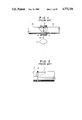
FIGS. 1 and 2 are partial longitudinal cross-sectional views of prior art construction;
FIG. 3a is a partial cross-sectional view of a construction similar to FIG. 2 for detecting the residual stress distributions due to welding;
FIG. 3b is a graphical illustration of the actual residual stress distributions;
FIG. 4a is an a partial cross-sectional view depicting a case where a conventional method is applied to the weld zone shown in FIG. 3a;
FIG. 4b is a graphical illustration of residual stress distributions showing the result of the stress-improving treatment conducted in accordance with the method of FIG. 4a;
FIG. 5 is a partial cross-secional view of the basic concept of the method of the invention;
FIG. 6 is a cross-sectional view taken along the central portion of the pipe shown in FIG. 5;
FIG. 7 is a graphical illustration of the stress distributions in the inner surface of the pipe shown in FIG. 5 along the length thereof;
FIG. 8 is a graphical illustration depicting the behavior between stress and strain, for explaining the effect of the invention;
FIG. 9a is a partial cross-sectional view of an embodiment of the invention;
FIGS. 9b to 9d are graphical illustrations of the effects of the embodiment shown in FIG. 9a;
FIG. 10 is a partial cross-sectional view of an example of the application of the invention;
FIG. 11 is a partial cross-sectional view of a modified embodiment of the invention; and
FIG. 12 is a schematic detail of deformation preventing clamp used in the embodiment of FIG. 11.
DETAILED DESCRIPTION
Referring now to the drawings wherein like reference numerals are used throughout the various views to designate like parts and, more particularly, to FIG. 1, according to this figure, stress-improving method using a high-frequency induction heating, comprises the steps of providing, around the outer periphery of the annular circumferential weld zone 2 of pipes 1b and 1b, a high-frequency induction heating coil 3 for local heating and rapidly heating the weld zone through a high-frequency induction heating device 5 and a cable 6 while cooling the inner surface of pipes 1a and 1b by a coolant 4. By the rapid heating, a temperature differential occurs in the direction of wall thickness so that the temperature at the outer surface of the weld zone is high and, at the inner surface of the same is low. Consequently, a tensile stress occurs in the inner surface due to the heating, and, when the temperature difference between the inner and outer surfaces of piping is in the order of 200° C., a tensile yield occurs in the inner surface thereby causing a tensile permanent set. When the heating treatment is finished and the temperature difference between the inner and outer surfaces becomes zero, a compressive stress occurs corresponding to the tensile permanent set brought about by the heating. Namely, the residual stress in the inner surface of the pipe which was at a tensile stress before being heated, can be relieved.
However, as shown in FIG. 2, where one member 7 in the circumferential weld zone has a higher rigidity than the other member 1, the stress improvement in the inner surface can not be obtained. For example, the weld zone 2 shown in FIG. 3a and has a residual stress distribution such as shown in FIG. 3b. As shown in FIG. 4a with the heating coil 3 arranged in a manner shown in FIG. 1, the weld zone 2 is rapidly heated to about 500° C. at its outer surface, resulting in a relieving of the tensile residual stress as shown in FIG. 4b, but not achieving a remarkable improving effect. In situations wherein one member 7 to be welded has a higher rigidity than the other member 8, the residual stress in weld zone 2 can not be sufficiently relieved by the conventional method.
As shown in FIGS. 5 and 6 in accordance with the present invention when outwardly concentrated loads are radially applied to the cross-section of a hollow cylinder, a local expanding deformation is caused in the inner surface of the hollow cylinder and local bending stress distribution such as shown in FIG. 7 occur therein. Namely, for the inner surface, a compressive stress occurs in the region A of |x/t|≲2, whereas a tensile stress occurs in the region B of 2<|x/t|≲10. In FIG. 7, the solid line represents the strain distribution and the dotted line represents the stress distribution in the inner surface which is schematically shown in FIG. 8. Namely, the hysteretic route 0→ ○1 → ○2 → ○3 represents a behavior of the region A in which, by the load, a compressive stress is applied thereby causing the compressive yield ○1 and the compressive plastic strain ○2 and then the compressive stress decreases as the load is removed and when the load is completely removed the tensile stress ○3 remains. On the other hand, the hysteretic route 0→ ○1' → ○2' → ○3' represents a behavior of the region B in which by the load a tensile stress is applied thereby causing the tensile yield ○1' and the tensile plastic strain ○2' and then the tensile stress decreases as the load is removed and when the load is completely removed the compressive stress ○3' remains. By virtue of the invention aforesaid aspect, i.e., when the load is applied under such a condition that the circumferential weld zone in which a tensile residual stress exists coincides with the region B, the tensile residual stress ○2' occurs by a small load because in the region B the state ○1' exists at the start of application of load, and when the load is removed the state ○3' occurs, so that it is possible to improve the tensile residual stress state ○1' to the compressive residual stress state ○3' by the small load.
FIG. 9a provides an illustrated example of an embodiment of the invention applied to a circumferential weld zone between a tube plate 7 a shell 8 of a heat exchanger. In the prior art, it has not been possible to satisfactorily improve the residual stress in the circumferential weld zone of the type illustrated in FIG. 9a. In this embodiment, a means for imparting a local expanding deformation of FIGS. 5 and 6 includes a heating coil 3 surrounding and spaced from the circumferential weld zone 2 by a distance L which is given by L=0.54√Rt or by L=2t, where R represents the radius of the shell, while t represents the wall thickness of the shell. The coil 3 is energized by a high-frequency induction heating device 5 through cable 6. In operation, the coil 3 is excited by a high-frequency current so that a high-frequency current is induced in the portion of the shell 8 covered by the coil 3 to heat this portion of the shell, while the inner surface is cooled by a coolant such as still water, flowing water, sprayed water and the like. Since the inner surface is cooled so that a temperature differential occurs in the wall thickness, and an expanding deformation approximately corresponding to a average temperature is caused in the portion of shell covered by the coil thereby causing a local bending action in the vicinity of each axial end of the coil 3, so that the effect mentioned in the foregoing paragraph can be obtained. This local bending action is larger at the an axial end of the coil 3 in the side at which the weld zone exists than at the coil's other axial end. FIG. 9b shows the residual stress distributions in the inner surface when the shell is heated until the average temperature in the wall thickness of fthe shell covered by the coil 3 becomes 350° C. By comparing FIG. 9b with FIG. 3b, it will be seen that, by virtue of the invention, the tensile residual stress due to welding is relieved to the compressive residual stress. Further, by comparing with FIG. 4, the difference from the prior art can also be clearly recognized.
Since the effectiveness has been confirmed, next, the results of analysis on the optimum position of the coil 3 are described hereinbelow. FIG. 9c shows a general tendency of the residual stress distribution when the distance Hc between the tube plate's end face (a portion where the rigidity drastically changes from a high level to a low level) and the axial end of the coil 3 has been made large, and represents a fact that when the distance Hc is too large the tensile residual stress occurs in the vicinity of the end of the tube plate face, so that it becomes harmful. Defining that, on the basis of the tube plate's end face, Hq is a point at which the stress changes from tensile stress to compressive stress, that Hg is a point at which the stress reversely changes from compressive stress to tensile stress, and further that Hr and Hs are points at which the compressive stress starts to become lower than -5 Kgf/mm2 and higher than -5 Kgf/mm2, respectively. The parameters are represented, in FIG. 9d, on the axis of odinate in terms of (Hp, Hq, Hr, Hs)/√Rt and the coil position Hc is represented on the axis of abscissa in terms of Hc/√Rt. From this, it will be seen that under a condition of Hc/√Rt≧1.2 the stress improvement in the vicinity of the tube plate's end face can not be obtained. From FIG. 9d, the optimum position of coil 3 can be determined in such a manner as mentioned hereinafter. Namely, assuming in FIG. 9c that the welding position is Hw, when the value Hw/√Rt is 0.4, for example, the value Hw/√Rt=0.4 is plotted on the axis of ordinate in FIG. 9d and then the coil may be set to the value Hc/√Rt=0.88 which corresponds to a central point (represented by double circle mark) between the curve Hr-Hc and the curve Hs-Hc. As an actual value of Hw, the value Hw/√Rt=0.2 to 0.5 is often adopted, and when it is assumed as a stress improving effect that the compressive residual stress of about -5 Kgf/mm2 is a standard, it is concluded that the optimum coil position corresponds to the value Hc/√Rt=0.81 to 0.92.
Since the shell 8 is heated while cooling its inner surface, in the portion of shell covered by the coil 3 such a temperature differential ΔT in the wall thickness occurs that the temperature is high in the outer surface and low in the inner surface. In the case of a mere expanding deformation, a tensile residual stress occurs in the aforesaid portion as in the region A explained above but since there is the temperature differential ΔT such an advantage is brought about that when the shell is heated the tensile yield occurs in the inner surface and finally the compressive stress remains therrein. Further, this advantage is promoted by the fact that the high-frequency heating is in itself a heating method which can easily cause the temperature differential ΔT because the heat is generated in surface layer of the shell 8.
The invention can be applied not only to the case where the rigidities of two members to be welded are extremely different as in the circumferential weld zone 2 between the tube plate 7 and the shell 8 but also to the circumferential weld zone 2 between a nozzle 9 and a pipe 1 as shown in FIG. 10.
Further, in the case where the difference in rigidity between both sides of the circumferential weld zone is small, it is possible to enhance the local bending action as shown in FIG. 11, by providing a deformation preventing means on a side of the heating coil 3 facing to the circumferential weld zone 2. In the embodiment of FIG. 11, the deformation is prevented by providing a detachable clamp 10 including two halves connected with pins 12a, and 12b and threadably securing the clamping bolts 11a to 11h. FIG. 12 shows the deformation preventing clamp in its as-detached state. Hydraulic cylinders may be provided in place of the clamping bolts. the advantage of the detachable clamp 12 resides in the fact that, by threadably attaching the clamping bolts 11a to 11h, a tensile stress occurs in the inner surface of weld zone 2 and it is possible, in cooperation with the local bending action brought about by heating with the coil 3, to enhance the effect of improving the residual stress to the compressive residual stress.
In the abovementioned embodiments, the high-frequency heating with cooling of the inner surface is utilized as a means for imparting the local expanding deformation, but even if the cooling is omitted the present invention can nevertheless improve a reduction in the tensile residual stress due to welding.
Further, as may be understood from all of the embodiments mentioned hereinbefore, since it is not necessary to use inside a pipe or vessel a special means, the characteristic of the abovementioned embodiments resides in a point that the invention can be applied to an already complete piping or vessel without disassembling or cutting the same.

Claims (9)

What is claimed is:
1. A method for improving residual stress of a weld zone between two stainless steel cylinders, one of which has a higher rigidity than the other, the method comprising the steps of: spacing an induction heating coil from the weld zone by a distance of 0.54 √Rt in a longitudinal direction of the cylinders, where R equals a radius of a cylinder, and t equals a wall thickness of the cylinder, heating the outer surface of the other cylinder by using the induction heating coil, and cooling the inner surface of the other cylinder during the induction heating.
2. A method for improving residual stress in the circumferential weld zone of a cylindrical apparatus, the method comprising the steps of: providing a means for preventing a deformation of said weld zone; causing a portion of one of said cylinders which is axially spaced from said weld zone by a predetermined distance to locally expand or contract by induction heating to thereby effect a plastic working so as to increase or decrease the diameter of the cylinder, said predetermined distance being a distance of 0.54 √Rt in a longitudinal direction of the cylinder, where R equals a radius of the cylinder and t equals a wall thickness of the cylinder; and cooling an inner surface of the other cylinder during the induction heating.
3. A method according to claim 1, wherein one of said cylinders is a tube plate of a heat exchanger.
4. A method according to claim 2, wherein one of said cylinders is a tube plate of a heat exchanger.
5. A method according to claim 1, wherein the spacing step is effected such that the axial faces of the coil surround the other cylinder and are spaced from the weld zone.
6. A method according to claim 1, wherein the heating step is effected so as to apply a radially outwardly concentrated load to aa cross-section of the other cylinder and thereby cause a local expanding deformation in an inner surface of the other cylinder such that local bending stress distributions occur therein to improve the residual stress.
7. A method according to claim 1, wherein the heating step is effective to heat only the outer surface of the other cylinder.
8. A method according to claim 3, wherein the heating step is continued until an average temperature of 350° C. in a wall of other cylinder is reached.
9. A method according to claim 4, wherein the induction heating is continued until an average temperature of 350° C. in a wall of said one of said cylinders is reached.
US07/015,624 1983-10-05 1987-02-17 Method of improving residual stress in circumferential weld zone Expired - Lifetime US4772336A (en)

Applications Claiming Priority (2)

Application Number Priority Date Filing Date Title
JP58185062A JPS6077919A (en) 1983-10-05 1983-10-05 Method for relieving residual stress in circumferential weld zone
JP58-185062 1983-10-05

Related Parent Applications (1)

Application Number Title Priority Date Filing Date
US06658170 Continuation 1984-10-05

Publications (1)

Publication Number Publication Date
US4772336A true US4772336A (en) 1988-09-20

Family

ID=16164138

Family Applications (1)

Application Number Title Priority Date Filing Date
US07/015,624 Expired - Lifetime US4772336A (en) 1983-10-05 1987-02-17 Method of improving residual stress in circumferential weld zone

Country Status (2)

Country Link
US (1) US4772336A (en)
JP (1) JPS6077919A (en)

Cited By (7)

* Cited by examiner, † Cited by third party
Publication number Priority date Publication date Assignee Title
US4822176A (en) * 1987-05-21 1989-04-18 Brown Boveri Reaktor Gmbh Method and apparatus for simulation of the operational demands acting an expanded tube joints
US5013370A (en) * 1989-03-27 1991-05-07 General Electric Company Method for localization of tensile residual stress and product produced thereby
US5158435A (en) * 1991-11-15 1992-10-27 Praxair Technology, Inc. Impeller stress improvement through overspeed
RU2309993C2 (en) * 2005-10-11 2007-11-10 Открытое акционерное общество "Ракетно-космическая корпорация "Энергия" им. С.П. Королева" Local heat-treatment apparatus
US20090183804A1 (en) * 2008-01-22 2009-07-23 Caterpillar Inc. Localized induction heating for residual stress optimization
RU2384632C2 (en) * 2008-06-10 2010-03-20 Федеральное Государственное Унитарное Предприятие "Научно-Производственное Объединение "Техномаш" Method of welded seam thermal treatment and device to this end
US10335795B2 (en) * 2012-10-26 2019-07-02 Thyssenkrupp Industrial Solutions Ag Gyratory crusher for comminuting material to be crushed

Citations (4)

* Cited by examiner, † Cited by third party
Publication number Priority date Publication date Assignee Title
US4168190A (en) * 1976-04-27 1979-09-18 Daiichi Koshuha Kogyo Kabushiki Kaisha Method for locally solution-treating stainless material
US4229235A (en) * 1977-10-25 1980-10-21 Hitachi, Ltd. Heat-treating method for pipes
US4354883A (en) * 1978-06-07 1982-10-19 Daiichi Kashuha Kogyo Kabushiki Kaisha Method for improving the residual stress in austenitic stainless steel pipes and the like by induction heating
US4505763A (en) * 1981-07-08 1985-03-19 Hitachi, Ltd. Heat-treating method of weld portion of piping system and heating coil for the heat treatment

Family Cites Families (1)

* Cited by examiner, † Cited by third party
Publication number Priority date Publication date Assignee Title
JPS6017636B2 (en) * 1977-09-02 1985-05-04 株式会社日立製作所 Welding method

Patent Citations (4)

* Cited by examiner, † Cited by third party
Publication number Priority date Publication date Assignee Title
US4168190A (en) * 1976-04-27 1979-09-18 Daiichi Koshuha Kogyo Kabushiki Kaisha Method for locally solution-treating stainless material
US4229235A (en) * 1977-10-25 1980-10-21 Hitachi, Ltd. Heat-treating method for pipes
US4354883A (en) * 1978-06-07 1982-10-19 Daiichi Kashuha Kogyo Kabushiki Kaisha Method for improving the residual stress in austenitic stainless steel pipes and the like by induction heating
US4505763A (en) * 1981-07-08 1985-03-19 Hitachi, Ltd. Heat-treating method of weld portion of piping system and heating coil for the heat treatment

Cited By (8)

* Cited by examiner, † Cited by third party
Publication number Priority date Publication date Assignee Title
US4822176A (en) * 1987-05-21 1989-04-18 Brown Boveri Reaktor Gmbh Method and apparatus for simulation of the operational demands acting an expanded tube joints
US5013370A (en) * 1989-03-27 1991-05-07 General Electric Company Method for localization of tensile residual stress and product produced thereby
US5158435A (en) * 1991-11-15 1992-10-27 Praxair Technology, Inc. Impeller stress improvement through overspeed
RU2309993C2 (en) * 2005-10-11 2007-11-10 Открытое акционерное общество "Ракетно-космическая корпорация "Энергия" им. С.П. Королева" Local heat-treatment apparatus
US20090183804A1 (en) * 2008-01-22 2009-07-23 Caterpillar Inc. Localized induction heating for residual stress optimization
US8075714B2 (en) 2008-01-22 2011-12-13 Caterpillar Inc. Localized induction heating for residual stress optimization
RU2384632C2 (en) * 2008-06-10 2010-03-20 Федеральное Государственное Унитарное Предприятие "Научно-Производственное Объединение "Техномаш" Method of welded seam thermal treatment and device to this end
US10335795B2 (en) * 2012-10-26 2019-07-02 Thyssenkrupp Industrial Solutions Ag Gyratory crusher for comminuting material to be crushed

Also Published As

Publication number Publication date
JPS6077919A (en) 1985-05-02

Similar Documents

Publication Publication Date Title
GB1595670A (en) Method of forming a connection between and an assembly of two metallic parts
US4727641A (en) Thermoplastic method of reducing the diameter of a metal tube
US4772336A (en) Method of improving residual stress in circumferential weld zone
JPS6161911B2 (en)
US4683014A (en) Mechanical stress improvement process
JP4448791B2 (en) Method and apparatus for improving residual stress in piping
JPS5950730B2 (en) How to improve residual stress in austenitic stainless steel pipes, etc.
JPH0418204B2 (en)
US4588869A (en) Method for relieving residual stresses by controlling weld heat input
US4807801A (en) Method of ameliorating the residual stresses in metallic duplex tubes and the like and apparatus therefor
CN116060796A (en) A device for thermal field regulation and control of welding deformation of thin-walled cylinder girth seam
JPS5952689B2 (en) Method for improving residual stress on the inner and outer surfaces of steel pipes
Murakawa et al. Mechanical Behavior in Local Postweld Heat Treatment
JPS63199075A (en) How to weld metal pipes
JPH06182578A (en) Method and equipment for welding pipings
JP2637518B2 (en) Piping reinforcement welding method
CN110587069A (en) Welding method for circumferential weld of bimetal metallurgy composite pipe
JPH0246654B2 (en) CHUKUTAINOZANRYUORYOKUKAIZENHOHO
JPS5852428A (en) Heat treatment for improving stress of shaft
JPS58122198A (en) Construction of welded joint of corrosion resistant pipe
JP3139052B2 (en) Stress improvement method for welded welds on metal pipe end faces
Umemoto et al. Application of induction heating stress improvement to the joint between the recirculation inlet nozzle and the safe-end weld
JPS5857253B2 (en) How to line odd-shaped materials
JPS6313777B2 (en)
JPH08261388A (en) Residual stress improvement method

Legal Events

Date Code Title Description
AS Assignment

Owner name: HITACHI, LTD., 6, KANDA SURUGADAI 4-CHOME, CHIYODA

Free format text: ASSIGNMENT OF ASSIGNORS INTEREST.;ASSIGNORS:ENOMOTO, KUNIO;SHIMIZU, TASUKU;SAKATA, SHINJI;AND OTHERS;REEL/FRAME:004824/0994

Effective date: 19841011

Owner name: HITACHI, LTD., A CORP OF JAPAN,JAPAN

Free format text: ASSIGNMENT OF ASSIGNORS INTEREST;ASSIGNORS:ENOMOTO, KUNIO;SHIMIZU, TASUKU;SAKATA, SHINJI;AND OTHERS;REEL/FRAME:004824/0994

Effective date: 19841011

STCF Information on status: patent grant

Free format text: PATENTED CASE

FEPP Fee payment procedure

Free format text: PAYOR NUMBER ASSIGNED (ORIGINAL EVENT CODE: ASPN); ENTITY STATUS OF PATENT OWNER: LARGE ENTITY

FPAY Fee payment

Year of fee payment: 4

FPAY Fee payment

Year of fee payment: 8

FPAY Fee payment

Year of fee payment: 12