US4769555A - Multi-time delay power controller apparatus with time delay turn-on and turn-off - Google Patents
Multi-time delay power controller apparatus with time delay turn-on and turn-off Download PDFInfo
- Publication number
- US4769555A US4769555A US07/077,425 US7742587A US4769555A US 4769555 A US4769555 A US 4769555A US 7742587 A US7742587 A US 7742587A US 4769555 A US4769555 A US 4769555A
- Authority
- US
- United States
- Prior art keywords
- time delay
- turn
- voltage
- timing
- time
- Prior art date
- Legal status (The legal status is an assumption and is not a legal conclusion. Google has not performed a legal analysis and makes no representation as to the accuracy of the status listed.)
- Expired - Lifetime
Links
Images



Classifications
-
- H—ELECTRICITY
- H02—GENERATION; CONVERSION OR DISTRIBUTION OF ELECTRIC POWER
- H02J—ELECTRIC POWER NETWORKS; CIRCUIT ARRANGEMENTS OR SYSTEMS FOR SUPPLYING OR DISTRIBUTING ELECTRIC POWER; SYSTEMS FOR STORING ELECTRIC ENERGY
- H02J3/00—Circuit arrangements for AC mains or AC distribution networks
- H02J3/12—Arrangements for adjusting voltage in AC networks by changing a characteristic of the network load
- H02J3/14—Arrangements for adjusting voltage in AC networks by changing a characteristic of the network load by switching loads on to, or off from, the networks, e.g. progressively balanced loading
-
- G—PHYSICS
- G05—CONTROLLING; REGULATING
- G05F—SYSTEMS FOR REGULATING ELECTRIC OR MAGNETIC VARIABLES
- G05F1/00—Automatic systems in which deviations of an electric quantity from one or more predetermined values are detected at the output of the system and fed back to a device within the system to restore the detected quantity to its predetermined value or values, i.e. retroactive systems
- G05F1/10—Regulating voltage or current
- G05F1/46—Regulating voltage or current wherein the variable actually regulated by the final control device is DC
- G05F1/56—Regulating voltage or current wherein the variable actually regulated by the final control device is DC using semiconductor devices in series with the load as final control devices
- G05F1/577—Regulating voltage or current wherein the variable actually regulated by the final control device is DC using semiconductor devices in series with the load as final control devices for plural loads
-
- H—ELECTRICITY
- H02—GENERATION; CONVERSION OR DISTRIBUTION OF ELECTRIC POWER
- H02H—EMERGENCY PROTECTIVE CIRCUIT ARRANGEMENTS
- H02H9/00—Emergency protective circuit arrangements for limiting excess current or voltage without disconnection
- H02H9/001—Emergency protective circuit arrangements for limiting excess current or voltage without disconnection limiting speed of change of electric quantities, e.g. soft switching on or off
-
- H—ELECTRICITY
- H02—GENERATION; CONVERSION OR DISTRIBUTION OF ELECTRIC POWER
- H02J—ELECTRIC POWER NETWORKS; CIRCUIT ARRANGEMENTS OR SYSTEMS FOR SUPPLYING OR DISTRIBUTING ELECTRIC POWER; SYSTEMS FOR STORING ELECTRIC ENERGY
- H02J9/00—Circuit arrangements for emergency or stand-by power supply, e.g. for emergency lighting
- H02J9/04—Circuit arrangements for emergency or stand-by power supply, e.g. for emergency lighting in which the distribution system is disconnected from the normal source and connected to a standby source
- H02J9/06—Circuit arrangements for emergency or stand-by power supply, e.g. for emergency lighting in which the distribution system is disconnected from the normal source and connected to a standby source with automatic change-over, e.g. UPS systems
- H02J9/061—Circuit arrangements for emergency or stand-by power supply, e.g. for emergency lighting in which the distribution system is disconnected from the normal source and connected to a standby source with automatic change-over, e.g. UPS systems for DC powered loads
-
- H—ELECTRICITY
- H02—GENERATION; CONVERSION OR DISTRIBUTION OF ELECTRIC POWER
- H02J—ELECTRIC POWER NETWORKS; CIRCUIT ARRANGEMENTS OR SYSTEMS FOR SUPPLYING OR DISTRIBUTING ELECTRIC POWER; SYSTEMS FOR STORING ELECTRIC ENERGY
- H02J2105/00—Networks for supplying or distributing electric power characterised by their spatial reach or by the load
- H02J2105/50—Networks for supplying or distributing electric power characterised by their spatial reach or by the load for selectively controlling the operation of the loads
- H02J2105/51—Networks for supplying or distributing electric power characterised by their spatial reach or by the load for selectively controlling the operation of the loads according to a condition being electrical
-
- Y—GENERAL TAGGING OF NEW TECHNOLOGICAL DEVELOPMENTS; GENERAL TAGGING OF CROSS-SECTIONAL TECHNOLOGIES SPANNING OVER SEVERAL SECTIONS OF THE IPC; TECHNICAL SUBJECTS COVERED BY FORMER USPC CROSS-REFERENCE ART COLLECTIONS [XRACs] AND DIGESTS
- Y02—TECHNOLOGIES OR APPLICATIONS FOR MITIGATION OR ADAPTATION AGAINST CLIMATE CHANGE
- Y02B—CLIMATE CHANGE MITIGATION TECHNOLOGIES RELATED TO BUILDINGS, e.g. HOUSING, HOUSE APPLIANCES OR RELATED END-USER APPLICATIONS
- Y02B70/00—Technologies for an efficient end-user side electric power management and consumption
- Y02B70/30—Systems integrating technologies related to power network operation and communication or information technologies for improving the carbon footprint of the management of residential or tertiary loads, i.e. smart grids as climate change mitigation technology in the buildings sector, including also the last stages of power distribution and the control, monitoring or operating management systems at local level
-
- Y—GENERAL TAGGING OF NEW TECHNOLOGICAL DEVELOPMENTS; GENERAL TAGGING OF CROSS-SECTIONAL TECHNOLOGIES SPANNING OVER SEVERAL SECTIONS OF THE IPC; TECHNICAL SUBJECTS COVERED BY FORMER USPC CROSS-REFERENCE ART COLLECTIONS [XRACs] AND DIGESTS
- Y02—TECHNOLOGIES OR APPLICATIONS FOR MITIGATION OR ADAPTATION AGAINST CLIMATE CHANGE
- Y02B—CLIMATE CHANGE MITIGATION TECHNOLOGIES RELATED TO BUILDINGS, e.g. HOUSING, HOUSE APPLIANCES OR RELATED END-USER APPLICATIONS
- Y02B70/00—Technologies for an efficient end-user side electric power management and consumption
- Y02B70/30—Systems integrating technologies related to power network operation and communication or information technologies for improving the carbon footprint of the management of residential or tertiary loads, i.e. smart grids as climate change mitigation technology in the buildings sector, including also the last stages of power distribution and the control, monitoring or operating management systems at local level
- Y02B70/3225—Demand response systems, e.g. load shedding, peak shaving
-
- Y—GENERAL TAGGING OF NEW TECHNOLOGICAL DEVELOPMENTS; GENERAL TAGGING OF CROSS-SECTIONAL TECHNOLOGIES SPANNING OVER SEVERAL SECTIONS OF THE IPC; TECHNICAL SUBJECTS COVERED BY FORMER USPC CROSS-REFERENCE ART COLLECTIONS [XRACs] AND DIGESTS
- Y04—INFORMATION OR COMMUNICATION TECHNOLOGIES HAVING AN IMPACT ON OTHER TECHNOLOGY AREAS
- Y04S—SYSTEMS INTEGRATING TECHNOLOGIES RELATED TO POWER NETWORK OPERATION, COMMUNICATION OR INFORMATION TECHNOLOGIES FOR IMPROVING THE ELECTRICAL POWER GENERATION, TRANSMISSION, DISTRIBUTION, MANAGEMENT OR USAGE, i.e. SMART GRIDS
- Y04S20/00—Management or operation of end-user stationary applications or the last stages of power distribution; Controlling, monitoring or operating thereof
- Y04S20/20—End-user application control systems
- Y04S20/222—Demand response systems, e.g. load shedding, peak shaving
-
- Y—GENERAL TAGGING OF NEW TECHNOLOGICAL DEVELOPMENTS; GENERAL TAGGING OF CROSS-SECTIONAL TECHNOLOGIES SPANNING OVER SEVERAL SECTIONS OF THE IPC; TECHNICAL SUBJECTS COVERED BY FORMER USPC CROSS-REFERENCE ART COLLECTIONS [XRACs] AND DIGESTS
- Y04—INFORMATION OR COMMUNICATION TECHNOLOGIES HAVING AN IMPACT ON OTHER TECHNOLOGY AREAS
- Y04S—SYSTEMS INTEGRATING TECHNOLOGIES RELATED TO POWER NETWORK OPERATION, COMMUNICATION OR INFORMATION TECHNOLOGIES FOR IMPROVING THE ELECTRICAL POWER GENERATION, TRANSMISSION, DISTRIBUTION, MANAGEMENT OR USAGE, i.e. SMART GRIDS
- Y04S20/00—Management or operation of end-user stationary applications or the last stages of power distribution; Controlling, monitoring or operating thereof
- Y04S20/20—End-user application control systems
- Y04S20/248—UPS systems or standby or emergency generators
Definitions
- the present invention relates generally to the field of power controller apparatus for electrical and electronic equipment, and more particularly to time delay power controller apparatus for such equipment.
- I is the current and dQ/dt is the time rate of charging (i.e., the charging rate).
- the combined effect of individual high turn-on currents of each of several or a number of pieces of electrical or electronic equipment is that the current carrying capacity of an existing building electrical circuit into which the equipment is connected may be exceeded. This typically causes the associated electrical circuit breaker to trip open at the instant the equipment is turned on, thereby shutting down all the equipment on the circuit. This may occur even though the building circuit has the capacity for safely handling the combined steady state operating currents of all the equipment.
- the present invention is, therefore, specifically directed to time delay power controller apparatus which provides time delayed power turn-off, with or without time delayed power turn-on being provided for the same equipment.
- Time delay power controller apparatus in accordance with the present invention comprises a power stage and means for connecting said power stage to a conventional power source, a plurality of time delayed outputs, a D.C. voltage bus and a ground, a D.C. power supply connected between the power stage and the D.C. bus and a plurality of time delay, turn-on timing stages connected between the D.C. bus and ground.
- Each of the turn-on timing delay stages comprises a timer initiating voltage input line, a time delay voltage output line, a control relay having an energizing coil connected to the time delay voltage output line and timing means connected between the timer initiating voltage input line and the time delay voltage output line for causing, a predetermined time interval after a change in voltage state appears on the timer initiating voltage input line, a voltage state change on the time delay voltage output line.
- the voltage state change on the time delay voltage output line is operative for causing the energizing of the control relay coil and thereby causing a time delayed voltage to be provided to a corresponding one of the time delayed outputs.
- Means are included in the apparatus for interconnecting the time delay timing stages in electrical series with one another so that the time delay voltage output line of each of the timing stages, except the last-in-sequence one thereof, is electrically connected to the timer initiating voltage input line of the next-in-sequence one of the timing stages. Also included are means for changing the voltage state on the timer initiating voltage input line of the first-in-sequence one of the timing stages to thereby initiate the timing sequence.
- the apparatus includes time delay turn-off means for de-energizing the relays in each of the turn-on timing delay stages in a preselected, time delay turn-off sequence.
- This time delayed de-energizing of each of the relays causes the removing of voltage from the corresponding one of the time delay outputs.
- the time delay turn-off means comprise a plurality of turn-off relays, each of which has contacts through which a corresponding one of the time delay turn-on control relays is energized when the turn-off relay contacts are closed.
- the time delay turn-off means include a plurality of time delay turn-off timing stages each of which corresponds to one of the time delay turn-on timing stages and is configured in a corresponding manner.
- the time delay turn-off means are responsive to a control signal turning the apparatus off and are preferably configured and operative for causing the removing of voltage from the time delayed outputs in the reverse order in which the control relays cause voltage to be provided to the outputs.
- each of the operating relays having contacts connected for providing voltage from the power stage to a corresponding one of the time delayed outputs and each being connected for being energized by a corresponding one of the control relays.
- the apparatus may be configured, for example by having the turn-on time delays equal to zero, so that time delay turn-off is provided without time delay turn-on of the time delayed outputs.
- FIG. 1 is a generalized functional block diagram of an exemplary time delay power controller apparatus, in accordance with the present invention, which has the combined capability for providing to outputs both time delayed turn-on and time delayed turn-off;
- FIG. 2 is an electrical schematic drawing of the time delay power controller apparatus of FIG. 1, FIG. 2a showing a plurality of time delay turn-on stages and FIG. 2b showing a plurality of time delay turn-off stages;
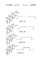
- FIG. 3 is a timing diagram showing voltages applied to and removed from time-delay outputs as a function of time after the apparatus is turned on and turned off;
- FIG. 3a showing voltages for an associated "master,” non-time delayed output;
- FIG. 3b showing voltages for a first time delay output;
- FIG. 3c showing voltages for a second time delay output; and
- FIG. 3d showing voltages for a third time delay output;
- FIG. 4 is a diagram showing time delay power outputs provided by the apparatus: FIG. 4a showing the output of a first time delay turn-on stage; FIG. 4b showing the output of a second time delay turn-on stage; FIG. 4c showing the output of a third time delay turn-on stage; FIG. 4d showing the output of a first time delay turn-off stage; FIG. 4e showing the output of a second time delay turn-off stage; and FIG. 4f showing the output of a third time delay turn-off stage; and
- FIG. 5 is a partial schematic drawing showing connection of the apparatus to a 208 volt, 3 phase power source.
- FIG. 1 An exemplary electronic or electrical system 10, in which multiple time delay power controller apparatus 12, according to the present invention, may be used to advantage.
- apparatus 12 is configured and is operative for controlling other pieces of electrical or electronic equipment (E.C.) such as those E.C.s designated, by way of illustrative example, in FIG. 1 by the reference numbers 14, 16, 18, 20 and 22, E.C.s 20 and 22 being shown in phantom lines for reasons to become apparent.
- E.C. electrical or electronic equipment
- apparatus 12 In general, the function of apparatus 12 is to provide timed delayed turn-on and turn-off controlling of E.C.s 14-22 (FIG. 1).
- one or more non-time delayed outputs may, for convenience or other purposes, be provided by apparatus 12.
- the time delayed outputs (as well as some or all of the non-time delayed outputs) may be of the power-type which directly power other equipment or of the signal-type which provide operating controls to other equipment not powered by apparatus 12.
- apparatus 12 is depicted in FIG. 1 as providing both power-type and signal-type outputs. Accordingly, E.C.s 14, 16 and 18 are shown as being directly powered, through respective lines 30, 32 and 34, from apparatus power outputs 36, 38 and 40, respectively. In addition, E.C.s 20 and 22 are shown as being connected by respective signal lines 42 and 44 to apparatus control signal outputs 46 and 48. Apparatus 12 may thus provide operating signals to E.C.s 20 and 22 which are separately connected, by respective power lines or cords 50 and 52, to power plugs 54 and 56.
- Power is provided to apparatus 12 from an existing building electrical outlet 66 through a power cord or line 68.
- Building outlet 66 may, according to one version of apparatus 12, be selected to provide conventional 110 volt, A.C. power, or may, as more particularly described below (with respect to FIG. 5), be selected to provide 208 volt, 3 phase power.
- apparatus 12 may advantageously be constructed to provide both time delayed turn-on and time delayed turn-off. It is to be appreciated, however, that apparatus 12 may alternatively be constructed to provide only time delayed turn-on or only time delayed turn-off; although, there may not be any great advantage to providing time delayed turn-off in the absence of time delay turn-on.
- the time delayed turn-on portion of apparatus 12 will be described first. Then, with this time delayed turn-on description as a foundation, the time delayed turn-off portion, which is generally similar to the time delay turn-on portion, of apparatus 12 will be described. As will also become apparent, both the time delayed turn-on and the time delayed turn-off portions share other, common portions of apparatus 12.
- FIG. 2 is a specific circuit diagram illustrating a preferred embodyment of the invention. In this FIG. it should be noted that all relays are, for purposes of consistency, shown in the de-energized condition.
- apparatus 12 principally comprises, as depicted in the circuit schematic drawing of FIG. 2a, generally a power portion or stage 74 (which is connected by line 68 to building power outlet 66), a D.C. power supply 76, an emergency shut off stage 78, an actuating or turn-on stage 80, a relay stage 82, respective first, second and third time delay turn-on stages 84, 85 and 88 and an output stage 90. Also shown in FIG. 2a is a turn-off initiating portion 92.
- power stage 74 provides A.C. power to other portions of apparatus 12, including, in the present embodiment, output stage 90, via an electrical conduit 94.
- D.C. power supply 76 provides D.C. voltage, for example, about 12-13 volts D.C., to turn-on timing delay stages 84, 86 and 88 (and also, as described below, to corresponding turn-off timing stages) for the operation thereof.
- Emergency shut-off stage 78 causes an automatic shut off of apparatus 12 in the event an associated emergency line 96 is shorted (i.e., grounded).
- Actuating stage 80 is operative for turning on apparatus 12 and for thereby starting the time delay sequencing described below.
- Timing delay stages 84, 86 and 88 provide a sequence of progressively time delayed signals which, through relay stage 82, control output stage 90.
- apparatus 12 provides a single, non-time delay output identified on such FIG. as “Master” and first, second and third time delayed (turn-on and turn-off) outputs, respectively identified as “Delay 1," “Delay 2" and “Delay 3.”
- the "Master” and three “Delays” correspond generally to outputs 36, 38, 40 and 46 of FIG. 1.
- first, second and third timing delay stages 84, 86 and 88 are shown in FIG. 2a, it will be apparent from the following description that additional, in-series turn-on timing delay stages (not shown) can readily be provided downstream of third stage 88 according to particular commercial or customer requirements.
- first, second and third turn-on timing delay stages 84, 86 and 88 are not identical but that odd numbered (i.e., first, third, fifth, seventh . . . ) stages are configured the same as one another and that even numbered (i.e., second, fourth, sixth, eighth . . . ) stages, only second stage 86 of which is illustrated, are configured the same as one another. As will be described below, there exist important differences between the odd and even numbered stages.
- D.C. power supply 76 comprises a conventional center tap transformer 98 which receives power from power stage 74, two diodes 100 and a capacitor 102. (The capacitance of all capacitors shown in FIG. 2 are in microfarads ( ⁇ f) unless otherwise noted on such FIG.) Components of power supply 76 are selected to provide about 12-13 volts D.C., through emergency shutoff stage 78, to one side of a relay 104 (also designated as K2 in FIG. 2a).
- timing delay turn-on stages 84, 86 and 88 are connected in electrical parallel with one another and between D.C. bus 110 and ground; however, these three stages operate sequentially, the timing out of one stage initiating the timing of the next-in-sequence stage.
- K2 relay 104 also causes the closing of K2 relay contacts 112 which thereby causes power to be applied, through conduit 94, to the non-time delayed "Master" output.
- the energizing of K2 relay 104 energizes D.C. bus 110 and starts the sequential operation of turn-on timing stages 84, 86 and 88, as described below, and simultaneously causes voltage to be applied to the non-time delayed "Master" output (FIG. 3a).
- First timing stage 84 comprises an R-C circuit 116, connected between D.C. voltage bus 110 and ground, a type 555 integrated circuit 118 and a normally-open control relay 120 (K1) having an energizing coil 122, one side of which is connected to ground.
- Type 555 circuit 118 is connected between R-C circuit 116 and a time delay output line 124 to which is connected, through normally closed contacts 125 of a relay 127 (relay K7, FIG. 2b), to the other side of K1 relay coil 122.
- Configuration of first stage 84 is such that at time t o , when D.C. voltage from power supply 76 is provided to bus 110 by the closing of K2 relay contacts 109, the voltage provided to one side (pins 2 and 6, as shown in FIG. 2a) of type 555 circuit 118 decreases from the voltage towards ground, the voltage decrease time being equal to the time delay interval, ⁇ t m , provided by R-C circuit 116.
- Time delay voltage output line 124 is connected, through a diode 126, to a timer initiating voltage input line 128 of second timer stage 86 in such a manner that at time, t o , such output line is at ground potential, K1 relay coil 122 being thereby non-energized
- K1 relay contacts 130 remain closed until apparatus 12 is subsequently turned off, at which time, all relay coils may be de-energized at once, or may, as more particularly described below, be de-energized in a time delayed sequence so that connected pieces of equipment are turned off in a predetermined, time delayed manner.
- K1 relay contacts 130 are connected by conduit 94 to apply line voltage to "Delay 1" output when such contacts are closed.
- K1 relay contacts may be connected to D.C. bus 110 to apply bus voltage to "Delay 1" output.
- line voltage or alternatively, D.C. bus voltage
- K1 contacts 130 to "Delay 1" output, such voltage being maintained until apparatus 12 is turned voltage being maintained until apparatus 12 is turned off, as described below.
- Second timing stage 86 is similar to the above-described first timing stage 84 and comprises an R-C circuit 138, a type 555 integrated circuit 140 and a normally-open control relay 142 (K3) having an energizing coil 144.
- a time delay voltage input line 146 is connected to an output (pin 3) of type 555 circuit 140, input pins 2 and 6 of such circuit being connected to R-C circuit 138 and pins 4 and 8 thereof being connected to D.C. bus 110.
- second timing stage 86 and first timing stage 84 A principal and significant difference between second timing stage 86 and first timing stage 84 is, however, that second stage relay coil 144 is connected between time delay output voltage line 146 and D.C. bus 110, through normally closed contacts 149 of a relay 150 (K6).
- FIG. 2b instead of between such output line and ground, as is the case for corresponding first stage K1 relay coil 122.
- voltage output line 146 goes to D.C. bus voltage when bus 110 is energized (assuming K6 relay contacts 149 are closed).
- R-C circuit 116 and type 555 integrated circuit 118 function together as a timing circuit or means, the R-C circuit providing a ramping voltage which causes or enables the associated type 555 circuit to change the voltage state on output line 124 when the voltage provided by the R-C circuit ramps down to a predetermined voltage level.
- time delay output line 124 which is electrically connected through diode 126 to timer initializing voltage input line 128 of second timing stage 86, remains at ground potential until R-C circuit 116 and type 555 circuit "time out" (at time t1). At such time, type 555 circuit 118 flips the voltage state on output line 124 to D.C. bus voltage. Such flipping of voltage state on output line 124 turns off diode 126 and thereby starts the charging of second stage R-C circuit 138 from ground potential towards D.C. bus voltage.
- type 555 circuit 140 When, at a time t 2 , after a charging time interval, ⁇ t b , pins 2 and 6 of type 555 circuit 140, which are connected to R-C circuit 138, reach about 2/3 D.C. bus voltage, the type 555 circuit causes the voltage state on pin 3 and hence on time delay voltage output line 146 to flip from D.C. bus voltage to ground (FIG. 4b). This voltage state change on output line 146 from bus voltage to ground causes K3 relay coil 144 to be energized, thereby closing K3 relay contacts 148 (FIG. 3c) and providing voltage to "Delay 2" output.
- R-C circuit 138 and type 555 circuit 140 function together as timing means.
- Output line 146 of second timing stage 86 is connected through a diode 154 to timer initiating voltage input line 156 of third timing stage 88.
- the flipping of second stage output line 146 from bus voltage to ground potential at time, t 2 turns off diode 154, thereby causing an R-C circuit 158 of third time delay timing stage 88 to start discharging from D.C. bus voltage to ground potential.
- Third time delay timing stage 88 is preferably a replicate of first timing stage 84, comprising, in addition to R-C circuit 158, a type 555 integrated circuit 160 and a normally-open relay 162 (K4) having a relay coil 164 and contacts 166 (in relay stage 82).
- K4 relay coil 164 is connected, through normally closed contacts 165 of a relay 167 (K5), to a time delayed voltage output line 168 which is, in turn, connected to output pin 3 of type 555 circuit 160.
- the other side of K4 relay coil 164 is connected to ground.
- R-C circuit 158 and type 555 circuit 160 function together as a timer or timing means.
- one side of the relay coil of every odd numbered timing stage (for example, relay coils 122 and 164 of first and third stages 84 and 88, respectively) is connected to ground.
- one side of the relay coil of every even numbered timing stage (for example, coil 144 of second stage 86 and a corresponding coil of a fourth stage--not shown--which might be connected in series with third stage 86) is connected to D.C. bus 110.
- K4 relay coil 164 When output line 168 is at ground potential, K4 relay coil 164 remains unenergized and K4 relay contacts 166 remain open. When, at time t 3 , D.C. bus voltage is applied to output line 168, K4 relay 164 is energized (assuming contacts 165 of K5 relay 157 remain closed), thereby closing K4 contacts 166 and applying voltage to "Delay 3" output (FIG. 3d).
- second and third turn-on timing stages 86 and 88 assures that the second stage does not enter its timing delay cycle until time t1, when first timing stage 84 "times out," and that the third stage does not enter its timing delay cycle until the second stage "times out” at time t 2 .
- outputs "Delay 1,” “Delay 2" and “Delay 3" are provided voltage in a time delayed sequence at times t 1 , t 2 and t 3 , such time delayed outputs being maintained until apparatus 12 is turned off.
- the turning off of these outputs may be in a time delayed manner so that the outputs are step-wise de-energized.
- the present inventors have determined that satisfactory time delayed turn-on operation of apparatus 12 cannot be achieved if all timing delay stages are constructed identically with relay coils 122, 144 and 164 all being connected either to ground or to D.C. bus 110. For example, it has been found that if second and third timing stages 86 and 88 are constructed identically with first timing stage 84, on and off voltage pulses are applied to "Delay 2" and "Delay 3" outputs before the desired time delayed control voltages are provided to such outputs. To prevent such occurrance by having all relay coils 122, 144 and 164 connected in the same manner either to ground or to D.C. bus 110 would require that R-C circuits 138 and 158 be constructed to provide delays equal respectively to ( ⁇ t a + ⁇ t b ) and ( ⁇ t a + ⁇ t b + ⁇ t c ).
- each power output may be connected (e.g., through respective relays 176, 178 and 180) to receive power from a different one of the power source phases.
- the power source is a conventional 208 volt, 3 phase source
- each power output is thus provided with about 115 volts. Powering apparatus 12 in such a manner is advantageous in that greater power can be delivered to the apparatus power outputs than is generally otherwise possible when each power output is connected through apparatus 12 to a conventional 110 volt power source.
- the energizing of the delayed outputs "Delay 1" through “Delay 3" is controlled through time delay stages 84, 86 and 88, by relays 122 (K1), 142 (K2) and 162 (K4), the "Master" output being energized through K2 relay 104 which also energizes D.C. bus 110.
- the energizing of relays 122, 142 and 162 is, as was described, controlled respectively by contacts 125, 148 and 165 of respective K7, K6 and K5 relays 127, 150 and 167, which, with other circuitry of apparatus 12, provide time delayed turn-off of the outputs.
- K10 relay 106 in association with relay 104 (K2), FIG. 2a.
- K10 relay 106 Connected in parallel with K10 relay 106 is a diode 202 and connected in series with such K10 relay is a diode 204.
- a diode 206 is connected in series with K2 relay 104, still another diode 208 being connected between both diodes 204, 206 and ground.
- Both relays 104 (K2) and 106 (K10) are connected through respective diodes 204 and 206 and through K9 contacts 107 to REMOTE/LOCAL switch 105, shown in FIG. 2a as part of output portion 90.
- Portion 92 comprises K5 and K9 relays 167 and 108 in parallel.
- a diode 220 is connected in parallel with K5 relay 167 and capacitors 222 and 224 are connected in parallel with K9 relay 108.
- Portion 92 is connected to the output of transformer 98 through series diodes 226 and 228.
- One side of both K5 and K7 relays 167 and 127 are grounded through respective normally open contacts 230 and 232 of K10 relay 106 and a relay 234 (K11) which is connected to the output of third time delay turn-on stage 88.
- the other side of K11 relay 234 is connected to ground through normally closed contacts 236 of a relay 240 (K8).
- a conduit 250 which is connected to D.C. bus 110 provides voltage, through normally open contacts 252 of K5 relay 167, to a D.C. bus 254 which extends through stages 244, 246 and 248 which are in electrical parallel between the bus and ground, but which, as described below, are connected to operate in sequence.
- first turn-off time delay stage 244 Generally comprising first turn-off time delay stage 244 are an R-C circuit 260, a type 555 integrated circuit 262 and K6 relay 150. Similarly comprising second turn-off time delay stage 246 are an R-C circuit 264, a type 555 circuit 266 and K7 relay 127. In turn generally comprising third turn-off time delay stage 248 are an R-C circuit 270, a type 555 circuit 272 and K8 relay 240. Configuration and operation of first, second and third turn-off time delay stages 244, 246 and 248, respectively, are substantially the same as described above for corresponding ones of first, second and third turn-on time delay stages 84, 86 and 88, with respect to FIG. 2a, and can, therefore, best be described in terms of their operation in controlling the turn off of "Delay 1" through "Delay 3" outputs.
- K5 contacts 252 close and D.C. voltage is applied, through conduit 250, to time delay turn-off bus 254 to start the operation of first, second and third turn-off stages 244, 246 and 248, respectively.
- the voltage at pins 2 and 6 of type 555 circuit 262 of first time delay turn-off stage 244 is taken to the voltage of bus 254 and then begins to decay to ground through the resistor in R-C circuit 260.
- pin 3 of type 555 circuit 262 switches to D.C. bus voltage (FIG. 4d), thereby energizing K6 relay 150.
- K6 relay 150 When K6 relay 150 is so energized, its contacts 149 (FIG. 2a) open circuit coil 144 of K3 relay (in second turn-on time delay stage 86), thereby disabling (de-energizing) "Delay 2" output (FIG. 3c) at time t 5 .
- pins 2 and 6 of type 555 circuit 266 of second turn-off time delay stage 246 start ramping up to the D.C. voltage of bus 254.
- pin 3 of type 555 circuit 266 switches from bus voltage to ground (FIG. 4e), thereby energizing K7 relay 127.
- This energizing of K7 relay 127 opens K7 contacts 125 and de-energizes K1 relay 120 in first turn-on time delay stage 84 (FIG. 2a), thereby disabling (deenergizing) "Delay 1" at time t 6 .
- pins 2 and 6 of type 555 circuit 272 start decreasing in voltage to ground from D.C. bus voltage.
- pin 3 of 555 circuit 272 switches to bus voltage (FIG. 4f), thereby energizing K8 relay 240.
- K8 relay contacts 236 FIG. 2a
- K11 relay 234 which, in turn, causes K2 relay 104 (FIG.
- apparatus 12 is configured for providing a time delayed turn-off of "Master" and "Delay 1" through “Delay 3" outputs in the reverse sequence of their turn on, it is to be appreciated that it is within the scope of the invention to provide for other sequences of turning off the outputs. Also, it is to be appreciated that the time delayed turn-off sequencing can be applied to outputs which have been turned on simultaneously. In such case, time delay turn-on stages 84, 86 and 88 may each be configured for a zero turn-on time delay.
- capacitors C-18 and C-19 (222 and 224), which are in parallel with K9 relay 108, provide a release delay for such relay.
- This release delay prevents an associated sequencer from turning all controlled outputs on if the contact closure is restored between "RO" and "RR” or REMOTE/LOCAL switch 105 is set to "ON" during the time delay turn-off sequence described above.
- This release delay of K9 relay 108 also ensures that both the time delay turn-on circuitry and the time delay turn-off circuitry are properly reset before a time delay turn-on sequence can be started.
- Resistor R11 limits in-rush current to capacitors C18 and C19 to a suitable value.
- Diode CR25 restricts the discharge path of the capacitors to only K9 relay 108.
- Diodes CR8, CR10, CR14, CR18, CR20 and CR22 provide quick discharge paths for their respective R-C circuits.
- Resistors R6 and R7 limit discharge current during reset conditions to a value suitable for the associated relays.
- Diodes CR4 (206), CR5, CR6, CR& and CR28 provide circuit protection from undesired external voltages and currents which might inadvertently be applied to remote control terminals "RO" and "RE.”
- timing resistors R2, R3, R4, R8, R9, and R10 are selectable to provide different time periods for both the time delay turn-on and turn-off sequences.
Landscapes
- Engineering & Computer Science (AREA)
- Power Engineering (AREA)
- Automation & Control Theory (AREA)
- Emergency Management (AREA)
- Physics & Mathematics (AREA)
- Electromagnetism (AREA)
- General Physics & Mathematics (AREA)
- Radar, Positioning & Navigation (AREA)
- Business, Economics & Management (AREA)
- Power Sources (AREA)
- Direct Current Feeding And Distribution (AREA)
- Keying Circuit Devices (AREA)
- Electronic Switches (AREA)
- Control Of Multiple Motors (AREA)
- Inverter Devices (AREA)
- Relay Circuits (AREA)
- Automatic Cycles, And Cycles In General (AREA)
- Power Conversion In General (AREA)
- Supply And Distribution Of Alternating Current (AREA)
Priority Applications (5)
| Application Number | Priority Date | Filing Date | Title |
|---|---|---|---|
| US07/077,425 US4769555A (en) | 1985-10-01 | 1987-07-24 | Multi-time delay power controller apparatus with time delay turn-on and turn-off |
| DE8787116705T DE3779122D1 (de) | 1987-07-24 | 1987-11-12 | Mehrfachleistungsregelapparat mit totzeit-einschalten und -ausschalten. |
| EP87116705A EP0300091B1 (de) | 1987-07-24 | 1987-11-12 | Mehrfachleistungsregelapparat mit Totzeit-Einschalten und -Ausschalten |
| AT87116705T ATE76209T1 (de) | 1987-07-24 | 1987-11-12 | Mehrfachleistungsregelapparat mit totzeiteinschalten und -ausschalten. |
| JP62307351A JPS6443027A (en) | 1987-07-24 | 1987-12-04 | Time delay electric source controller |
Applications Claiming Priority (2)
| Application Number | Priority Date | Filing Date | Title |
|---|---|---|---|
| US06/782,307 US4719364A (en) | 1985-10-01 | 1985-10-01 | Multiple time delay power controller apparatus |
| US07/077,425 US4769555A (en) | 1985-10-01 | 1987-07-24 | Multi-time delay power controller apparatus with time delay turn-on and turn-off |
Related Parent Applications (1)
| Application Number | Title | Priority Date | Filing Date |
|---|---|---|---|
| US06/782,307 Continuation-In-Part US4719364A (en) | 1985-10-01 | 1985-10-01 | Multiple time delay power controller apparatus |
Publications (1)
| Publication Number | Publication Date |
|---|---|
| US4769555A true US4769555A (en) | 1988-09-06 |
Family
ID=22137967
Family Applications (1)
| Application Number | Title | Priority Date | Filing Date |
|---|---|---|---|
| US07/077,425 Expired - Lifetime US4769555A (en) | 1985-10-01 | 1987-07-24 | Multi-time delay power controller apparatus with time delay turn-on and turn-off |
Country Status (5)
| Country | Link |
|---|---|
| US (1) | US4769555A (de) |
| EP (1) | EP0300091B1 (de) |
| JP (1) | JPS6443027A (de) |
| AT (1) | ATE76209T1 (de) |
| DE (1) | DE3779122D1 (de) |
Cited By (54)
| Publication number | Priority date | Publication date | Assignee | Title |
|---|---|---|---|---|
| US5243232A (en) * | 1991-07-31 | 1993-09-07 | Allen-Bradley Company, Inc. | Start-up pulse suppression circuit for industrial controller output |
| US5384490A (en) * | 1992-06-15 | 1995-01-24 | Unisys Corporation | Universal power distribution system |
| US5424903A (en) * | 1993-01-12 | 1995-06-13 | Tandy Corporation | Intelligent power switcher |
| US5450334A (en) * | 1993-11-01 | 1995-09-12 | Pulizzi Engineering, Inc. | One time programmable switched-output controller |
| EP0692108A4 (de) * | 1993-04-02 | 1997-01-29 | Cirrus Logic Inc | Stufenleistungsregelung |
| US5627722A (en) * | 1994-12-05 | 1997-05-06 | Hewlett-Packard Company | Single high voltage supply for use in a multiple developer electrophotographic printer |
| US5923103A (en) * | 1997-03-31 | 1999-07-13 | Pulizzi Engineering, Inc. | Switched-output controller apparatus with repeater function and method for constructing same |
| US6011329A (en) * | 1998-08-28 | 2000-01-04 | Mcgovern; Patrick T. | Electrical circuit cycling controller |
| US6388854B1 (en) * | 1999-12-09 | 2002-05-14 | International Business Machines Corporation | Load balancing and distributing switch-on control for a circuit breaker, an appliance, a device, or an apparatus |
| US20020069373A1 (en) * | 2000-12-04 | 2002-06-06 | Jesse Zhuo | Safe shutdown device for an uninterruptible power supply (UPS) system and method for safely shuting down a UPS system |
| US20020134567A1 (en) * | 2001-03-20 | 2002-09-26 | Neil Rasmussen | Adjustable scalable rack power system and method |
| US20030121689A1 (en) * | 2002-01-02 | 2003-07-03 | Neil Rasmussen | Toolless mounting system and method for an adjustable scalable rack power system |
| US20030137788A1 (en) * | 2000-08-01 | 2003-07-24 | Rolf Dickhoff | Safety switching device for safely switching off an electrical load |
| US20040047095A1 (en) * | 2002-05-06 | 2004-03-11 | Cyber Switching, Inc. | Method and/or system and/or apparatus for multiple interface remotely configurable power supply |
| US20040064198A1 (en) * | 2002-05-06 | 2004-04-01 | Cyber Switching, Inc. | Method and/or system and/or apparatus for remote power management and monitoring supply |
| US6741442B1 (en) * | 2000-10-13 | 2004-05-25 | American Power Conversion Corporation | Intelligent power distribution system |
| US6766222B1 (en) * | 2000-06-14 | 2004-07-20 | Advanced Micro Devices, Inc. | Power sequencer control circuit |
| US20040231875A1 (en) * | 2001-03-20 | 2004-11-25 | Neil Rasmussen | Adjustable scalable rack power system and method |
| US20050134119A1 (en) * | 2003-12-18 | 2005-06-23 | Bliley Paul D. | Time slotting power switching |
| US20050203987A1 (en) * | 1996-07-23 | 2005-09-15 | Server Technology, Inc. | Network power administration system |
| US20050278075A1 (en) * | 2004-05-28 | 2005-12-15 | Neil Rasmussen | Methods and apparatus for providing and distributing standby power |
| US20060031454A1 (en) * | 1996-07-23 | 2006-02-09 | Ewing Carrel W | Network-connected power manager for rebooting remote computer-based appliances |
| US20060072269A1 (en) * | 2004-09-30 | 2006-04-06 | Staples Peter E | Amperage apparatus for displaying ralative amperage load |
| US20060072262A1 (en) * | 2004-09-28 | 2006-04-06 | American Power Conversion Corporation | System and method for allocating power to loads |
| US20060072531A1 (en) * | 2004-10-04 | 2006-04-06 | Ewing Carrel W | Communication network |
| US20060116023A1 (en) * | 2004-09-20 | 2006-06-01 | Spitaels James S | Equipment rack data/power distribution |
| US20060292924A1 (en) * | 2005-06-15 | 2006-12-28 | Kelly Spiri | Power control circuit |
| US20070018506A1 (en) * | 2005-07-22 | 2007-01-25 | American Power Conversion Corporation | Apparatus and method for preventing an electrical backfeed |
| US20070033438A1 (en) * | 2005-08-03 | 2007-02-08 | Wellsyn Technology, Inc. | Method and system for controlling powers of a plurality of servers |
| US20070076340A1 (en) * | 1996-07-23 | 2007-04-05 | Server Technology, Inc. | Electrical power distribution device having a current display |
| US20070168088A1 (en) * | 2005-11-02 | 2007-07-19 | Server Technology, Inc. | Power distribution load shedding system and method of use |
| US20070256104A1 (en) * | 2006-04-27 | 2007-11-01 | Wei-Chih Huang | Image-processing system capable of controlling multiple display devices |
| US20070291437A1 (en) * | 2006-06-16 | 2007-12-20 | Gefran S.P.A. | Power Regulator Supplied to Electric Charges of Industrial Processes |
| US20070291430A1 (en) * | 2006-06-16 | 2007-12-20 | American Power Conversion Corporation | Apparatus and method for scalable power distribution |
| CN100357857C (zh) * | 2005-03-25 | 2007-12-26 | 威盛电子股份有限公司 | 主机板、电子元件及逻辑操作控制方法 |
| US20080258556A1 (en) * | 2004-07-31 | 2008-10-23 | Ewing Carrel W | Transfer Switch With Arc Suppression |
| US20090033151A1 (en) * | 2007-08-02 | 2009-02-05 | Zippy Technology Corp. | Modularized power supply switch control structure |
| US20090096287A1 (en) * | 2007-10-15 | 2009-04-16 | Weiliang Jiang | Power source for electric appliances and electric appliances adopting the power source thereof |
| US20090242265A1 (en) * | 2008-03-31 | 2009-10-01 | Panduit Corp. | Power Outlet Unit |
| US7606014B2 (en) | 2006-06-16 | 2009-10-20 | American Power Conversion Corporation | Apparatus and method for scalable power distribution |
| US20100020475A1 (en) * | 2007-06-21 | 2010-01-28 | American Power Conversion Corporation | Apparatus and method for scalable power distribution |
| US20100141046A1 (en) * | 2008-12-04 | 2010-06-10 | American Power Conversion Corporation | Energy reduction |
| US20100145884A1 (en) * | 2008-12-04 | 2010-06-10 | American Power Conversion Corporation | Energy savings aggregation |
| US20110136353A1 (en) * | 2009-12-03 | 2011-06-09 | Spitaels James S | Apparatus and method for scalable power distribution |
| US20120194952A1 (en) * | 2008-08-07 | 2012-08-02 | Crucs Holdings, Llc | Controllable electrical outlet and a method of operation thereof |
| US20120236442A1 (en) * | 2009-12-02 | 2012-09-20 | Manchanahally Venkataramasastry Satyanarayana | intelligent controller |
| US20120313454A1 (en) * | 2011-06-08 | 2012-12-13 | John Mezzalingua Associates, Inc. | Power control device |
| US8560652B2 (en) | 1996-07-23 | 2013-10-15 | Server Technology, Inc. | Remote power control system |
| US20140022685A1 (en) * | 2011-03-24 | 2014-01-23 | Feng Miao | Method and Arrangement for Reducing In-Rush Current of Multi-Module System |
| US9104393B2 (en) | 1996-07-23 | 2015-08-11 | Server Technology, Inc. | Power-manager configuration upload and download method and system for network managers |
| US9792552B2 (en) | 2012-06-29 | 2017-10-17 | Schneider Electric USA, Inc. | Prediction of available generator running time |
| US10353447B2 (en) * | 2017-03-03 | 2019-07-16 | Qualcomm Incorporated | Current in-rush mitigation for power-up of embedded memories |
| CN112313118A (zh) * | 2018-06-21 | 2021-02-02 | 纬湃科技有限责任公司 | 用于提供多个供电电压的电路装置 |
| CN115534845A (zh) * | 2022-09-28 | 2022-12-30 | 中通客车股份有限公司 | 一种客车上电控制及下电延时系统 |
Families Citing this family (7)
| Publication number | Priority date | Publication date | Assignee | Title |
|---|---|---|---|---|
| US4918562A (en) * | 1989-01-30 | 1990-04-17 | Pulizzi Engineering, Inc. | Power controller with voltage-controlled circuit breaker |
| US5117747A (en) * | 1991-07-18 | 1992-06-02 | Kuechler Irvin R | Broiler for meat products and the like |
| DE4219398A1 (de) * | 1992-06-13 | 1993-12-16 | Claas Ohg | Gepufferte Spannungsversorgung für Bordelektronik |
| DE10217235A1 (de) * | 2002-04-18 | 2003-10-30 | Philips Intellectual Property | Schaltungsanordnung zur Erzeugung von Gleichspannungen |
| US7566987B2 (en) | 2006-09-14 | 2009-07-28 | Lutron Electronics Co., Inc. | Method of powering up a plurality of loads in sequence |
| US7781919B2 (en) * | 2006-09-14 | 2010-08-24 | Lutron Electronics Co., Inc. | Method of controlling a load control module as part of a startup sequence |
| US7741732B2 (en) | 2006-09-14 | 2010-06-22 | Lutron Electronics Co., Inc. | Method of configuring a startup sequence of a load control system |
Citations (22)
| Publication number | Priority date | Publication date | Assignee | Title |
|---|---|---|---|---|
| US3050713A (en) * | 1959-12-16 | 1962-08-21 | Bell Telephone Labor Inc | Output selecting circuit |
| US3178591A (en) * | 1959-05-13 | 1965-04-13 | Bailey Meter Co | Scanning apparatus employing filter capacitor havcing short charge-time and long, but with means to reduce, discharge-time |
| US3229164A (en) * | 1962-12-17 | 1966-01-11 | William B Mccartney | Electrical recycling circuit for controlling and protecting functional equipment |
| US3258613A (en) * | 1966-06-28 | Apparatus for selectively supplying electrical pulses op different widths to a plurality of load devices | ||
| US3560769A (en) * | 1967-05-09 | 1971-02-02 | Tokai Rika Co Ltd | Sequential flasher |
| US3628068A (en) * | 1970-06-25 | 1971-12-14 | Us Navy | Sequential timing system |
| US3639844A (en) * | 1969-06-27 | 1972-02-01 | Whirlpool Co | Electronic timer for a multiple function appliance |
| US3700914A (en) * | 1970-11-20 | 1972-10-24 | Tappan Co The | Control apparatus for air conditioning and like systems |
| US3801872A (en) * | 1973-02-27 | 1974-04-02 | Ite Imperial Corp | Multi-shot reclosing relay having means for remembering trip and reclosure status in the event of loss of power |
| US3826955A (en) * | 1973-02-09 | 1974-07-30 | O Fest | Time delay relay |
| US4011517A (en) * | 1975-01-22 | 1977-03-08 | Stromberg-Carlson Corporation | Timer apparatus for incrementing timing code at variable clock rates |
| US4016474A (en) * | 1975-04-25 | 1977-04-05 | Ecc Corporation | Circuit for controlling the charging current supplied to a plurality of battery loads in accordance with a predetermined program |
| US4177388A (en) * | 1978-07-10 | 1979-12-04 | Louise D. Suhey | Programmable control for load management |
| US4215277A (en) * | 1979-02-09 | 1980-07-29 | Robert I. Weiner | Sequencing light controller |
| US4227062A (en) * | 1978-05-31 | 1980-10-07 | General Electric Company | Optimum time ratio control system for microwave oven including food surface browning capability |
| US4234801A (en) * | 1978-02-22 | 1980-11-18 | Emhart Industries, Inc. | Control system utilizing momentary switching devices |
| US4245319A (en) * | 1979-03-19 | 1981-01-13 | Cyborex Laboratories, Inc. | Energy management method and apparatus utilizing duty cycle reduction synchronized with the zero points of the applied voltage |
| US4270573A (en) * | 1978-07-25 | 1981-06-02 | Hydronic Systems, Inc. | Controller for fluid flow systems |
| US4310770A (en) * | 1979-07-25 | 1982-01-12 | Ohio Agricultural Research And Development Center | Demand load control |
| US4400699A (en) * | 1978-08-04 | 1983-08-23 | G. Bauknecht Gmbh | Program selection apparatus |
| US4419590A (en) * | 1982-02-10 | 1983-12-06 | Diversified Electronics, Inc. | Sequencer for pump motors or the like |
| US4674031A (en) * | 1985-10-25 | 1987-06-16 | Cara Corporation | Peripheral power sequencer based on peripheral susceptibility to AC transients |
Family Cites Families (4)
| Publication number | Priority date | Publication date | Assignee | Title |
|---|---|---|---|---|
| US3894247A (en) * | 1973-12-26 | 1975-07-08 | Rockwell International Corp | Circuit for initalizing logic following power turn on |
| GB1536046A (en) * | 1976-06-30 | 1978-12-20 | Ibm | Data processing system power control |
| JPS5775304A (en) * | 1980-10-29 | 1982-05-11 | Fanuc Ltd | Power supply for controller |
| US4719364A (en) * | 1985-10-01 | 1988-01-12 | Pulizzi Engineering, Inc. | Multiple time delay power controller apparatus |
-
1987
- 1987-07-24 US US07/077,425 patent/US4769555A/en not_active Expired - Lifetime
- 1987-11-12 AT AT87116705T patent/ATE76209T1/de not_active IP Right Cessation
- 1987-11-12 DE DE8787116705T patent/DE3779122D1/de not_active Expired - Fee Related
- 1987-11-12 EP EP87116705A patent/EP0300091B1/de not_active Expired - Lifetime
- 1987-12-04 JP JP62307351A patent/JPS6443027A/ja active Pending
Patent Citations (22)
| Publication number | Priority date | Publication date | Assignee | Title |
|---|---|---|---|---|
| US3258613A (en) * | 1966-06-28 | Apparatus for selectively supplying electrical pulses op different widths to a plurality of load devices | ||
| US3178591A (en) * | 1959-05-13 | 1965-04-13 | Bailey Meter Co | Scanning apparatus employing filter capacitor havcing short charge-time and long, but with means to reduce, discharge-time |
| US3050713A (en) * | 1959-12-16 | 1962-08-21 | Bell Telephone Labor Inc | Output selecting circuit |
| US3229164A (en) * | 1962-12-17 | 1966-01-11 | William B Mccartney | Electrical recycling circuit for controlling and protecting functional equipment |
| US3560769A (en) * | 1967-05-09 | 1971-02-02 | Tokai Rika Co Ltd | Sequential flasher |
| US3639844A (en) * | 1969-06-27 | 1972-02-01 | Whirlpool Co | Electronic timer for a multiple function appliance |
| US3628068A (en) * | 1970-06-25 | 1971-12-14 | Us Navy | Sequential timing system |
| US3700914A (en) * | 1970-11-20 | 1972-10-24 | Tappan Co The | Control apparatus for air conditioning and like systems |
| US3826955A (en) * | 1973-02-09 | 1974-07-30 | O Fest | Time delay relay |
| US3801872A (en) * | 1973-02-27 | 1974-04-02 | Ite Imperial Corp | Multi-shot reclosing relay having means for remembering trip and reclosure status in the event of loss of power |
| US4011517A (en) * | 1975-01-22 | 1977-03-08 | Stromberg-Carlson Corporation | Timer apparatus for incrementing timing code at variable clock rates |
| US4016474A (en) * | 1975-04-25 | 1977-04-05 | Ecc Corporation | Circuit for controlling the charging current supplied to a plurality of battery loads in accordance with a predetermined program |
| US4234801A (en) * | 1978-02-22 | 1980-11-18 | Emhart Industries, Inc. | Control system utilizing momentary switching devices |
| US4227062A (en) * | 1978-05-31 | 1980-10-07 | General Electric Company | Optimum time ratio control system for microwave oven including food surface browning capability |
| US4177388A (en) * | 1978-07-10 | 1979-12-04 | Louise D. Suhey | Programmable control for load management |
| US4270573A (en) * | 1978-07-25 | 1981-06-02 | Hydronic Systems, Inc. | Controller for fluid flow systems |
| US4400699A (en) * | 1978-08-04 | 1983-08-23 | G. Bauknecht Gmbh | Program selection apparatus |
| US4215277A (en) * | 1979-02-09 | 1980-07-29 | Robert I. Weiner | Sequencing light controller |
| US4245319A (en) * | 1979-03-19 | 1981-01-13 | Cyborex Laboratories, Inc. | Energy management method and apparatus utilizing duty cycle reduction synchronized with the zero points of the applied voltage |
| US4310770A (en) * | 1979-07-25 | 1982-01-12 | Ohio Agricultural Research And Development Center | Demand load control |
| US4419590A (en) * | 1982-02-10 | 1983-12-06 | Diversified Electronics, Inc. | Sequencer for pump motors or the like |
| US4674031A (en) * | 1985-10-25 | 1987-06-16 | Cara Corporation | Peripheral power sequencer based on peripheral susceptibility to AC transients |
Cited By (113)
| Publication number | Priority date | Publication date | Assignee | Title |
|---|---|---|---|---|
| US5243232A (en) * | 1991-07-31 | 1993-09-07 | Allen-Bradley Company, Inc. | Start-up pulse suppression circuit for industrial controller output |
| US5384490A (en) * | 1992-06-15 | 1995-01-24 | Unisys Corporation | Universal power distribution system |
| US5424903A (en) * | 1993-01-12 | 1995-06-13 | Tandy Corporation | Intelligent power switcher |
| EP0692108A4 (de) * | 1993-04-02 | 1997-01-29 | Cirrus Logic Inc | Stufenleistungsregelung |
| US5450334A (en) * | 1993-11-01 | 1995-09-12 | Pulizzi Engineering, Inc. | One time programmable switched-output controller |
| US5627722A (en) * | 1994-12-05 | 1997-05-06 | Hewlett-Packard Company | Single high voltage supply for use in a multiple developer electrophotographic printer |
| US20070130243A1 (en) * | 1996-07-23 | 2007-06-07 | Server Technology, Inc. | Electrical power distribution plugstrip with current information display and method of use |
| US20060259538A1 (en) * | 1996-07-23 | 2006-11-16 | Server Technology, Inc. | Network remote power management outlet strip |
| US9104393B2 (en) | 1996-07-23 | 2015-08-11 | Server Technology, Inc. | Power-manager configuration upload and download method and system for network managers |
| US20050203987A1 (en) * | 1996-07-23 | 2005-09-15 | Server Technology, Inc. | Network power administration system |
| US7702771B2 (en) | 1996-07-23 | 2010-04-20 | Server Technology, Inc. | Electrical power distribution device having a current display |
| US20070140238A1 (en) * | 1996-07-23 | 2007-06-21 | Server Technology, Inc. | Power management device with communications capability and method of use |
| US20070136453A1 (en) * | 1996-07-23 | 2007-06-14 | Server Technology, Inc. | Networkable electrical power distribution plugstrip with current display and method of use |
| US20070076340A1 (en) * | 1996-07-23 | 2007-04-05 | Server Technology, Inc. | Electrical power distribution device having a current display |
| US20070050443A1 (en) * | 1996-07-23 | 2007-03-01 | Server Technology, Inc. | Network remote power management outlet strip |
| US9450386B2 (en) | 1996-07-23 | 2016-09-20 | Server Technology, Inc. | Vertical-mount electrical power distribution plugstrip |
| US8489667B2 (en) | 1996-07-23 | 2013-07-16 | Server Technology, Inc. | Network power administration system |
| US20060031454A1 (en) * | 1996-07-23 | 2006-02-09 | Ewing Carrel W | Network-connected power manager for rebooting remote computer-based appliances |
| US8560652B2 (en) | 1996-07-23 | 2013-10-15 | Server Technology, Inc. | Remote power control system |
| US8510424B2 (en) | 1996-07-23 | 2013-08-13 | Server Technology, Inc. | Network-connected power manager for rebooting remote computer-based appliances |
| US5923103A (en) * | 1997-03-31 | 1999-07-13 | Pulizzi Engineering, Inc. | Switched-output controller apparatus with repeater function and method for constructing same |
| US6011329A (en) * | 1998-08-28 | 2000-01-04 | Mcgovern; Patrick T. | Electrical circuit cycling controller |
| US6388854B1 (en) * | 1999-12-09 | 2002-05-14 | International Business Machines Corporation | Load balancing and distributing switch-on control for a circuit breaker, an appliance, a device, or an apparatus |
| US6766222B1 (en) * | 2000-06-14 | 2004-07-20 | Advanced Micro Devices, Inc. | Power sequencer control circuit |
| US6809911B2 (en) * | 2000-08-01 | 2004-10-26 | Pilz Gmbh & Co. | Safety switching device for safely switching off an electrical load |
| US20030137788A1 (en) * | 2000-08-01 | 2003-07-24 | Rolf Dickhoff | Safety switching device for safely switching off an electrical load |
| JP2004505600A (ja) * | 2000-08-01 | 2004-02-19 | ピルツ ゲーエムベーハー アンド コー. | 安全スイッチング装置 |
| JP4824897B2 (ja) * | 2000-08-01 | 2011-11-30 | ピルツ ゲーエムベーハー アンド コー.カーゲー | 安全スイッチング装置 |
| US6741442B1 (en) * | 2000-10-13 | 2004-05-25 | American Power Conversion Corporation | Intelligent power distribution system |
| US20020069373A1 (en) * | 2000-12-04 | 2002-06-06 | Jesse Zhuo | Safe shutdown device for an uninterruptible power supply (UPS) system and method for safely shuting down a UPS system |
| US20100275441A1 (en) * | 2001-03-20 | 2010-11-04 | American Power Conversion Corporation | Adjustable scalable rack power system and method |
| US8867193B2 (en) | 2001-03-20 | 2014-10-21 | Schneider Electric It Corporation | Adjustable scalable rack power system and method |
| US7358439B2 (en) | 2001-03-20 | 2008-04-15 | American Power Conversion Corporation | Adjustable scalable rack power system and method |
| US8173898B2 (en) | 2001-03-20 | 2012-05-08 | American Power Conversion Corporation | Adjustable scalable rack power system and method |
| US8107225B2 (en) * | 2001-03-20 | 2012-01-31 | American Power Conversion Corporation | Adjustable scalable rack power system and method |
| US20040231875A1 (en) * | 2001-03-20 | 2004-11-25 | Neil Rasmussen | Adjustable scalable rack power system and method |
| US20110026193A1 (en) * | 2001-03-20 | 2011-02-03 | American Power Conversion Corporation | Adjustable scalable rack power system and method |
| US7675740B2 (en) | 2001-03-20 | 2010-03-09 | American Power Conversion Corporation | Adjustable scalable rack power system and method |
| US20020134567A1 (en) * | 2001-03-20 | 2002-09-26 | Neil Rasmussen | Adjustable scalable rack power system and method |
| US7718889B2 (en) | 2001-03-20 | 2010-05-18 | American Power Conversion Corporation | Adjustable scalable rack power system and method |
| US20090034166A1 (en) * | 2001-03-20 | 2009-02-05 | American Power Conversion Corporation | Adjustable scalable rack power system and method |
| US20060151190A1 (en) * | 2001-03-20 | 2006-07-13 | American Power Conversion Corporation | Adjustable scalable rack power system and method |
| US6967283B2 (en) | 2001-03-20 | 2005-11-22 | American Power Conversion Corporation | Adjustable scalable rack power system and method |
| US20030121689A1 (en) * | 2002-01-02 | 2003-07-03 | Neil Rasmussen | Toolless mounting system and method for an adjustable scalable rack power system |
| US7855872B2 (en) | 2002-01-02 | 2010-12-21 | American Power Conversion Corporation | Toolless mounting system and method for an adjustable scalable rack power system |
| US20050185363A1 (en) * | 2002-01-02 | 2005-08-25 | American Power Conversion Corporation | Toolless mounting system and method for an adjustable scalable rack power system |
| US20090034167A1 (en) * | 2002-01-02 | 2009-02-05 | American Power Conversion Corporation | Toolless mounting system and method for an adjustable scalable rack power system |
| US7425682B2 (en) | 2002-01-02 | 2008-09-16 | American Power Conversion Corporation | Toolless mounting system and method for an adjustable scalable rack power system |
| US20040047095A1 (en) * | 2002-05-06 | 2004-03-11 | Cyber Switching, Inc. | Method and/or system and/or apparatus for multiple interface remotely configurable power supply |
| US7550870B2 (en) | 2002-05-06 | 2009-06-23 | Cyber Switching, Inc. | Method and apparatus for remote power management and monitoring |
| US20040064198A1 (en) * | 2002-05-06 | 2004-04-01 | Cyber Switching, Inc. | Method and/or system and/or apparatus for remote power management and monitoring supply |
| US20050134119A1 (en) * | 2003-12-18 | 2005-06-23 | Bliley Paul D. | Time slotting power switching |
| US20090046415A1 (en) * | 2004-05-28 | 2009-02-19 | American Power Conversion Corporation | Methods and apparatus for providing and distributing standby power |
| US8670872B2 (en) | 2004-05-28 | 2014-03-11 | Schneider Electric It Corporation | Methods and apparatus for providing and distributing standby power |
| US7418314B2 (en) | 2004-05-28 | 2008-08-26 | American Power Conversion Corporation | Methods and apparatus for providing and distributing standby power |
| US7983797B2 (en) | 2004-05-28 | 2011-07-19 | American Power Conversion Corporation | Methods and apparatus for providing and distributing standby power |
| US20050278075A1 (en) * | 2004-05-28 | 2005-12-15 | Neil Rasmussen | Methods and apparatus for providing and distributing standby power |
| WO2005119878A1 (en) * | 2004-05-28 | 2005-12-15 | American Power Conversion Corporation | Methods and apparatus for providing and distributing standby power |
| US7142950B2 (en) | 2004-05-28 | 2006-11-28 | American Power Conversion Corporation | Methods and apparatus for providing and distributing standby power |
| US20070055409A1 (en) * | 2004-05-28 | 2007-03-08 | American Power Conversion Corporation | Methods and apparatus for providing and distributing standby power |
| US20080258556A1 (en) * | 2004-07-31 | 2008-10-23 | Ewing Carrel W | Transfer Switch With Arc Suppression |
| US9531215B2 (en) | 2004-07-31 | 2016-12-27 | Server Technology, Inc. | Transfer switch with arc suppression |
| US8138634B2 (en) | 2004-07-31 | 2012-03-20 | Server Technology, Inc. | Transfer switch with arc suppression |
| US20060116023A1 (en) * | 2004-09-20 | 2006-06-01 | Spitaels James S | Equipment rack data/power distribution |
| US8446040B2 (en) | 2004-09-28 | 2013-05-21 | Scheider Electric IT Corporation | System and method for allocating power to loads |
| US20060072262A1 (en) * | 2004-09-28 | 2006-04-06 | American Power Conversion Corporation | System and method for allocating power to loads |
| US20090121547A1 (en) * | 2004-09-28 | 2009-05-14 | American Power Conversion Corporation | System and method for allocating power to loads |
| US7514815B2 (en) | 2004-09-28 | 2009-04-07 | American Power Conversion Corporation | System and method for allocating power to loads |
| US20110049980A1 (en) * | 2004-09-28 | 2011-03-03 | American Power Conversion Corporation | System and method for allocating power to loads |
| US7786617B2 (en) | 2004-09-28 | 2010-08-31 | American Power Conversion Corporation | System and method for allocating power to loads |
| US20060072269A1 (en) * | 2004-09-30 | 2006-04-06 | Staples Peter E | Amperage apparatus for displaying ralative amperage load |
| US20060072531A1 (en) * | 2004-10-04 | 2006-04-06 | Ewing Carrel W | Communication network |
| CN100357857C (zh) * | 2005-03-25 | 2007-12-26 | 威盛电子股份有限公司 | 主机板、电子元件及逻辑操作控制方法 |
| US20060292924A1 (en) * | 2005-06-15 | 2006-12-28 | Kelly Spiri | Power control circuit |
| US7341481B2 (en) * | 2005-06-15 | 2008-03-11 | Dgc Products, Inc. | Power control circuit |
| US20070018506A1 (en) * | 2005-07-22 | 2007-01-25 | American Power Conversion Corporation | Apparatus and method for preventing an electrical backfeed |
| US7446437B2 (en) | 2005-07-22 | 2008-11-04 | American Power Conversion Corporation | Apparatus and method for preventing an electrical backfeed |
| USRE43177E1 (en) | 2005-07-22 | 2012-02-14 | American Power Conversion Corporation | Apparatus and method for preventing an electrical backfeed |
| US20070033438A1 (en) * | 2005-08-03 | 2007-02-08 | Wellsyn Technology, Inc. | Method and system for controlling powers of a plurality of servers |
| US7533281B2 (en) * | 2005-08-03 | 2009-05-12 | Aten International Co., Ltd. | Method and system for controlling powers of a plurality of servers |
| US20070168088A1 (en) * | 2005-11-02 | 2007-07-19 | Server Technology, Inc. | Power distribution load shedding system and method of use |
| US7605771B2 (en) * | 2006-04-27 | 2009-10-20 | Princeton Technology Corporation | Image-processing system capable of controlling multiple display devices |
| US20070256104A1 (en) * | 2006-04-27 | 2007-11-01 | Wei-Chih Huang | Image-processing system capable of controlling multiple display devices |
| US7606014B2 (en) | 2006-06-16 | 2009-10-20 | American Power Conversion Corporation | Apparatus and method for scalable power distribution |
| US8027134B2 (en) | 2006-06-16 | 2011-09-27 | American Power Conversion Corporation | Apparatus and method for scalable power distribution |
| US20090323258A1 (en) * | 2006-06-16 | 2009-12-31 | American Power Conversion Corporation | Apparatus and method for scalable power distribution |
| US7619868B2 (en) | 2006-06-16 | 2009-11-17 | American Power Conversion Corporation | Apparatus and method for scalable power distribution |
| US20070291437A1 (en) * | 2006-06-16 | 2007-12-20 | Gefran S.P.A. | Power Regulator Supplied to Electric Charges of Industrial Processes |
| US20070291430A1 (en) * | 2006-06-16 | 2007-12-20 | American Power Conversion Corporation | Apparatus and method for scalable power distribution |
| US20100020475A1 (en) * | 2007-06-21 | 2010-01-28 | American Power Conversion Corporation | Apparatus and method for scalable power distribution |
| US8503149B2 (en) | 2007-06-21 | 2013-08-06 | Schneider Electric It Corporation | Apparatus and method for scalable power distribution |
| US7940504B2 (en) | 2007-06-21 | 2011-05-10 | American Power Conversion Corporation | Apparatus and method for scalable power distribution |
| US7939964B2 (en) * | 2007-08-02 | 2011-05-10 | Zippy Technology Corp. | Modularized power supply switch control structure |
| US20090033151A1 (en) * | 2007-08-02 | 2009-02-05 | Zippy Technology Corp. | Modularized power supply switch control structure |
| US20090096287A1 (en) * | 2007-10-15 | 2009-04-16 | Weiliang Jiang | Power source for electric appliances and electric appliances adopting the power source thereof |
| US8876548B2 (en) | 2008-03-31 | 2014-11-04 | Panduit Corp. | Rack unit outlet spacing for power outlet units |
| US20090242265A1 (en) * | 2008-03-31 | 2009-10-01 | Panduit Corp. | Power Outlet Unit |
| US20120194952A1 (en) * | 2008-08-07 | 2012-08-02 | Crucs Holdings, Llc | Controllable electrical outlet and a method of operation thereof |
| US20100145884A1 (en) * | 2008-12-04 | 2010-06-10 | American Power Conversion Corporation | Energy savings aggregation |
| US8200370B2 (en) | 2008-12-04 | 2012-06-12 | American Power Conversion Corporation | Energy reduction |
| USRE46093E1 (en) | 2008-12-04 | 2016-08-02 | Schneider Electric It Corporation | Energy reduction |
| US8521336B2 (en) | 2008-12-04 | 2013-08-27 | American Power Conversion Corporation | Energy reduction |
| US20100141046A1 (en) * | 2008-12-04 | 2010-06-10 | American Power Conversion Corporation | Energy reduction |
| US20120236442A1 (en) * | 2009-12-02 | 2012-09-20 | Manchanahally Venkataramasastry Satyanarayana | intelligent controller |
| US20110136353A1 (en) * | 2009-12-03 | 2011-06-09 | Spitaels James S | Apparatus and method for scalable power distribution |
| US8212427B2 (en) | 2009-12-03 | 2012-07-03 | American Power Converison Corporation | Apparatus and method for scalable power distribution |
| US8610316B2 (en) | 2009-12-03 | 2013-12-17 | Schneider Electric It Corporation | Apparatus and method for scalable power distribution |
| US20140022685A1 (en) * | 2011-03-24 | 2014-01-23 | Feng Miao | Method and Arrangement for Reducing In-Rush Current of Multi-Module System |
| US20120313454A1 (en) * | 2011-06-08 | 2012-12-13 | John Mezzalingua Associates, Inc. | Power control device |
| US9792552B2 (en) | 2012-06-29 | 2017-10-17 | Schneider Electric USA, Inc. | Prediction of available generator running time |
| US10353447B2 (en) * | 2017-03-03 | 2019-07-16 | Qualcomm Incorporated | Current in-rush mitigation for power-up of embedded memories |
| CN112313118A (zh) * | 2018-06-21 | 2021-02-02 | 纬湃科技有限责任公司 | 用于提供多个供电电压的电路装置 |
| CN115534845A (zh) * | 2022-09-28 | 2022-12-30 | 中通客车股份有限公司 | 一种客车上电控制及下电延时系统 |
Also Published As
| Publication number | Publication date |
|---|---|
| EP0300091A3 (en) | 1989-06-14 |
| ATE76209T1 (de) | 1992-05-15 |
| EP0300091A2 (de) | 1989-01-25 |
| JPS6443027A (en) | 1989-02-15 |
| EP0300091B1 (de) | 1992-05-13 |
| DE3779122D1 (de) | 1992-06-17 |
Similar Documents
| Publication | Publication Date | Title |
|---|---|---|
| EP0300091B1 (de) | Mehrfachleistungsregelapparat mit Totzeit-Einschalten und -Ausschalten | |
| US4719364A (en) | Multiple time delay power controller apparatus | |
| US20050134121A1 (en) | Power distribution system and control system for same | |
| SE9103304L (sv) | Anordning foer omkoppling av en spaenningskaella till en elektrisk apparat | |
| US4354214A (en) | Motor protection circuit | |
| AU8153587A (en) | Discharge lamp control circuit | |
| EP0094166B1 (de) | Lichtkontrollsystem | |
| CA1303718C (en) | Multiple time delay power controller apparatus with time delay turn-on and turn-off | |
| JPH09284998A (ja) | 電源装置 | |
| CA1280501C (en) | Multiple time delay power controller apparatus | |
| US8076798B2 (en) | Uninterruptible A/C power supply transfer unit | |
| JPS626872Y2 (de) | ||
| JP2697837B2 (ja) | リセット回路 | |
| US2967978A (en) | Power supply fault sensing and protective control circuit | |
| JPH028532B2 (de) | ||
| JPH0243001Y2 (de) | ||
| JPS63314136A (ja) | 買電量制御装置 | |
| JPS5858840A (ja) | 多回路開閉器制御装置 | |
| JPH0622451A (ja) | 多出力電源負荷装置誤動作防止回路 | |
| RU177621U1 (ru) | Устройство управления питанием встраиваемого компьютера | |
| JPS5819607Y2 (ja) | 交流入力切換器 | |
| JPS6013248Y2 (ja) | 自動電源断回路 | |
| SU1629901A2 (ru) | Стабилизированный преобразователь посто нного напр жени | |
| JPH0334171B2 (de) | ||
| JPH054183Y2 (de) |
Legal Events
| Date | Code | Title | Description |
|---|---|---|---|
| STCF | Information on status: patent grant |
Free format text: PATENTED CASE |
|
| FPAY | Fee payment |
Year of fee payment: 4 |
|
| FEPP | Fee payment procedure |
Free format text: PAYOR NUMBER ASSIGNED (ORIGINAL EVENT CODE: ASPN); ENTITY STATUS OF PATENT OWNER: LARGE ENTITY |
|
| REMI | Maintenance fee reminder mailed | ||
| FPAY | Fee payment |
Year of fee payment: 8 |
|
| SULP | Surcharge for late payment | ||
| FEPP | Fee payment procedure |
Free format text: PAT HLDR NO LONGER CLAIMS SMALL ENT STAT AS SMALL BUSINESS (ORIGINAL EVENT CODE: LSM2); ENTITY STATUS OF PATENT OWNER: LARGE ENTITY |
|
| FPAY | Fee payment |
Year of fee payment: 12 |