US4755822A - Antenna mounting - Google Patents
Antenna mounting Download PDFInfo
- Publication number
- US4755822A US4755822A US06/927,204 US92720486A US4755822A US 4755822 A US4755822 A US 4755822A US 92720486 A US92720486 A US 92720486A US 4755822 A US4755822 A US 4755822A
- Authority
- US
- United States
- Prior art keywords
- electrical contact
- cam
- housing
- cam follower
- base
- Prior art date
- Legal status (The legal status is an assumption and is not a legal conclusion. Google has not performed a legal analysis and makes no representation as to the accuracy of the status listed.)
- Expired - Fee Related
Links
Images


Classifications
-
- H—ELECTRICITY
- H01—ELECTRIC ELEMENTS
- H01Q—ANTENNAS, i.e. RADIO AERIALS
- H01Q1/00—Details of, or arrangements associated with, antennas
- H01Q1/12—Supports; Mounting means
- H01Q1/22—Supports; Mounting means by structural association with other equipment or articles
- H01Q1/24—Supports; Mounting means by structural association with other equipment or articles with receiving set
Definitions
- This invention is generally directed to an apparatus for securing an antenna and, more particularly, to a housing for mounting the antenna of the rod type and simultaneous assurance of electrical contact with the input circuitry structure.
- the technology from which the antenna mounting technique drew its origins is the technology of radio, television and automobile antenna securing devices.
- the prior art required screw mounting the antenna in place. This made assembly and maintenance a time consuming ordeal.
- an antenna base an antenna housing having a hole for receiving the antenna base, an integral electrical contact and cam follower secured to the interior of the housing and forming a guide for receiving the antenna base as it is inserted into the hole in the housing, and a cam for moving the integral electrical contact and cam follower into mechanical and electrical engagement with the antenna base.
- the housing and cam are preferably made of plastic, the cam being a single molded piece.
- the integral electrical contact and cam follower is made of spring metal and biased to follow an inclined surface of the cam as it is rotated to securely lock the antenna base in place and simultaneously make good electrical contact therewith.
- the antenna may be easily released by again rotating the cam so as to release the spring bias of the cam follower and thereby allow the antenna base to be withdrawn from the housing.
- the cam is itself held in position within the housing by the integral electrical contact and cam follower which holds the cam against circumferential shoulders of an opening through which a portion of the cam projects.
- An optional rib can be used to prevent the cam follower from deflecting from the housing.
- the follower is bent at one end to make contact with a run on a printed circuit board.
- the portion of the cam which projects through the opening provides a means whereby the cam may be physically engaged for manual rotation. This may be a projection or a slot or both allowing manual grasping or insertion of a tool such as a screw driver or a coin.
- the cam is provided with a projection on its side which matingly engages a notch in the opening that, together with the spring bias of the integral electrical contact and cam follower, forms a detent when the cam is in the locked position.
- the cam is released from this detent position by turning the cam with the previously mentioned coin or other tool.
- the invention is characterized not only by the ease of installation and removal of an antenna to electrical circuitry such as a radio or other communications device, but also by the simplicity of its structure.
- the invention comprises only two major parts, the integral electrical contact and cam follower and the cam, which are mounted within a housing. This simplicity of structure decreases the cost of manufacture by minimizing the number of parts and the operations required for assembly.
- FIG. 1 is an exploded view of the antenna mount according to the invention
- FIG. lA is a perspective view of the antenna mount shown in FIG. 1 with an additional optional rib;
- FIG. 2 is a plan view showing the stamped blank from which the follower is formed
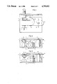
- FIG. 3 is a side view of the antenna mount
- FIG. 4 is a bottom view of the antenna mount in the unlocked position
- FIG. 5 is a bottom view of the antenna mount in the locked position
- FIG. 6 is a side view of the antenna mount showing the electrical connection to the printed circuit board.
- the antenna base 1 is a cylindrically shaped, solid piece of metal with a machined groove 2 to receive a thin, flat piece of metal.
- the top of the antenna base 1 has a hole 3 for attaching the antenna.
- the antenna (not shown) may be a telescoping whip or rod antenna of conventional design. The specific design of the antenna does not form a part of the invention.
- the antenna base 1 slides through a hole 4 in the antenna housing 5 and then through a folded area 6 of the follower 7 and comes to rest on the projection 8 integral with the interior of housing 5.
- the follower 7 is made from a single flat piece of spring metal.
- One end 9 of the follower 7 is bent in three places as indicated by the dotted lines in FIG. 2, the first two bends forming the end into a generally U-shape and the third bend causing the extreme end to incline slightly outwardly as depicted in FIG. 1.
- This bending results in a folded area 6 of the follower 7 which receives the antenna base 1.
- the inclined end 10 of the follower 7 has a larger area and includes a follower tab 11 which is a little narrower than the machined groove 2 of the antenna base 1.
- the other end 12 of the follower 7 is secured to an interior projection 13 of the housing 5 by means of a screw 14.
- the overhanging portion of the end 12 is provided with a through hole into which a wire connection may be inserted and soldered or an end 50, as depicted in FIG. 6, can be bent to make contact with a run on a printed circuit board. This would eliminate the requirement for a soldering operation and further reduce the cost of manufacture.
- the follower tab 11 and the folded area 6 hold the antenna base 1 in place when biased into the locking position by the cam 15.
- the cam 15 is a single molded piece of generally cylindrical shape.
- One end 16 of the cam is generally planar and formed at an oblique angle to the axis of the body of the cam.
- the other end 17 of the cam is of smaller diameter than the main body of the cam, the transition between the main body of the cam and the smaller diameter end 17 forming a circumferential shoulder 18.
- the housing 5 is formed with an inwardly projecting circular flange 19, forming a cam housing and having an inside diameter sufficiently large to receive and allow the main body of the cam 15 to rotate within the cam housing.
- the cam housing 19 is located midway between the projection 8 and 13.
- a circular opening 20 is provided in the housing 5 concentric with the cam housing 19, and this opening is just large enough to permit the smaller diameter end 17 of the cam 15 to project through the housing.
- the interior of the housing 5 between the interior surface of the cam housing 19 and the opening 20 forms a shoulder 21 which matingly engages the shoulder 18 of the cam 15.
- the face of the smaller diameter end 17 of the cam 15 is provided with a projection 22 and a slot 23 allowing for grasping by fingers or pliers or the insertion of a tool such as a screw driver or a coin to facilitate the rotation of the cam.
- the inclined end 10 of the follower 7 holds the cam 15 in the flange 19.
- the cam 15 is provided with a projection 24 which matingly engages a notch 25 in the flange 19 under the urging of the spring bias of the inclined end 10 of the follower 7 when the cam is turned to the locking position.
- the projection 24 and notch 25 cooperate to form a detent, and the cam 15 may be released from the detent position by applying a moderate turning force to projection 22, or slot 23 and rotating the cam 15.
- an optional rib 80 incorporating the projection 8, is added to form a guide for receiving the antenna base 1.
- the rib 80 surrounds and secures the cam follower 7.
- FIG. 4 shows the antenna mount from the bottom in the unlocked position.
- the antenna base 1 is held by the follower tab 11 and the folded area 6 of the follower 7.
- the follower tab 11 is moved away from the groove 2 in the antenna base 1 so that the antenna base may be easily inserted and withdrawn without interference.
- the folded area 6 of the follower 7 is also relaxed, providing a wider opening for receiving the antenna base 1.
- the cam's oblique end 16 applies pressure to the inclined end 10 of the follower 7 and forces the follower tab 11 securely onto the machined groove 2 of the antenna base 1.
- the folded area 6 is contracted about the antenna base 1 further enhancing the mechanical and electrical contact between the antenna base 1 and the follower 7.
- a secure mechanical lock of the antenna base is assured by the follower tab 11 engaging the shoulders of the the machined groove 2 and the detent action of the projection 24 in notch 25.
- the rib 80 is used to prevent the follower 7 from deflecting from the housing when the cam 15 is in the locked position.
- Assembly of the improved antenna mount is as follows.
- the cam 15 is slipped into the cam housing 19.
- the follower 7 is attached to the projection 13 by means of a screw so that the cam 15 is captured in the cam housing 19. This is all that is required to assemble the antenna mount.
- the antenna is installed by sliding the antenna base 1 through the hole 4 in the housing 5 and the folded area 6 of the follower 7 until it makes contact with the projection 8 integral to the housing 5.
- the cam 15 is then rotated to cause the follower tab 11 to engage the groove 2 in the antenna base 1 as bias is applied to the inclined end 10 of the follower 7.
- a good electrical connection is assured between the antenna base and the cam follower 7 by the machined groove 2 of the antenna base 1 that receives the follower tab 11 and the pressure from the constriction of the folded area 6 as a result of the rotation of cam 15. Disassembly is facilitated by turning the cam to the unlocked position. When in the unlocked position, the antenna base 1 may then be easily withdrawn.
- any standard antenna rod either the telescopic type or the standard fixed length rod may be accommodated by this apparatus. It will also be apparent that the services of a skilled technician should not be required to locate and install the antenna.
Abstract
Description
Claims (8)
Priority Applications (1)
| Application Number | Priority Date | Filing Date | Title |
|---|---|---|---|
| US06/927,204 US4755822A (en) | 1986-11-05 | 1986-11-05 | Antenna mounting |
Applications Claiming Priority (1)
| Application Number | Priority Date | Filing Date | Title |
|---|---|---|---|
| US06/927,204 US4755822A (en) | 1986-11-05 | 1986-11-05 | Antenna mounting |
Publications (1)
| Publication Number | Publication Date |
|---|---|
| US4755822A true US4755822A (en) | 1988-07-05 |
Family
ID=25454385
Family Applications (1)
| Application Number | Title | Priority Date | Filing Date |
|---|---|---|---|
| US06/927,204 Expired - Fee Related US4755822A (en) | 1986-11-05 | 1986-11-05 | Antenna mounting |
Country Status (1)
| Country | Link |
|---|---|
| US (1) | US4755822A (en) |
Cited By (4)
| Publication number | Priority date | Publication date | Assignee | Title |
|---|---|---|---|---|
| US5600334A (en) * | 1995-08-18 | 1997-02-04 | Cushcraft Corporation | Mobile antenna mount |
| US6064342A (en) * | 1998-07-13 | 2000-05-16 | 3Com Corporation | Antenna detachment mechanisms and methods |
| US6323812B1 (en) * | 2000-04-04 | 2001-11-27 | Motorola, Inc. | Secondary antenna ground element |
| US6685383B2 (en) | 2001-11-02 | 2004-02-03 | Radio Frequency Systems Inc. | Antenna and radio interface |
Citations (7)
| Publication number | Priority date | Publication date | Assignee | Title |
|---|---|---|---|---|
| US2319760A (en) * | 1939-12-02 | 1943-05-18 | Galvin Mfg Corp | Antenna system |
| US2396121A (en) * | 1945-02-07 | 1946-03-05 | Croname Inc | Portable radio receiver |
| US2439408A (en) * | 1942-02-20 | 1948-04-13 | Motorola Inc | Portable radio transmitting and receiving set |
| US2497687A (en) * | 1946-08-30 | 1950-02-14 | K L G Sparking Plugs Ltd | Radio aerial for use on vehicles |
| US2833849A (en) * | 1955-11-10 | 1958-05-06 | Abel Jack | Antenna mount for vehicles |
| US3484696A (en) * | 1967-03-31 | 1969-12-16 | Gen Electric | Direct antenna lead connection for a communications receiver |
| US3512162A (en) * | 1967-10-02 | 1970-05-12 | Gen Electric | Combination vhf antenna mounting clip and signal transfer |
-
1986
- 1986-11-05 US US06/927,204 patent/US4755822A/en not_active Expired - Fee Related
Patent Citations (7)
| Publication number | Priority date | Publication date | Assignee | Title |
|---|---|---|---|---|
| US2319760A (en) * | 1939-12-02 | 1943-05-18 | Galvin Mfg Corp | Antenna system |
| US2439408A (en) * | 1942-02-20 | 1948-04-13 | Motorola Inc | Portable radio transmitting and receiving set |
| US2396121A (en) * | 1945-02-07 | 1946-03-05 | Croname Inc | Portable radio receiver |
| US2497687A (en) * | 1946-08-30 | 1950-02-14 | K L G Sparking Plugs Ltd | Radio aerial for use on vehicles |
| US2833849A (en) * | 1955-11-10 | 1958-05-06 | Abel Jack | Antenna mount for vehicles |
| US3484696A (en) * | 1967-03-31 | 1969-12-16 | Gen Electric | Direct antenna lead connection for a communications receiver |
| US3512162A (en) * | 1967-10-02 | 1970-05-12 | Gen Electric | Combination vhf antenna mounting clip and signal transfer |
Cited By (6)
| Publication number | Priority date | Publication date | Assignee | Title |
|---|---|---|---|---|
| US5600334A (en) * | 1995-08-18 | 1997-02-04 | Cushcraft Corporation | Mobile antenna mount |
| US6064342A (en) * | 1998-07-13 | 2000-05-16 | 3Com Corporation | Antenna detachment mechanisms and methods |
| US6323812B1 (en) * | 2000-04-04 | 2001-11-27 | Motorola, Inc. | Secondary antenna ground element |
| US6685383B2 (en) | 2001-11-02 | 2004-02-03 | Radio Frequency Systems Inc. | Antenna and radio interface |
| US20040136778A1 (en) * | 2001-11-02 | 2004-07-15 | Alcatel | Antenna and radio interface |
| US7006054B2 (en) | 2001-11-02 | 2006-02-28 | Radio Frequency System, Inc. | Antenna and radio interface |
Similar Documents
| Publication | Publication Date | Title |
|---|---|---|
| US6469678B1 (en) | Antenna mounting apparatus | |
| US4934943A (en) | Automated connector alignment assembly for connection of printed circuit boards | |
| JP3935990B2 (en) | Connection member for electronic devices | |
| EP0524830A2 (en) | Self-mounting automobile dome lamp assembly | |
| US5919057A (en) | Removable main connector | |
| US6490894B1 (en) | Device for mounting a vehicle door opening control | |
| US4755822A (en) | Antenna mounting | |
| US6162103A (en) | Terminal structure of a connector | |
| EP1090807B1 (en) | Lever switch | |
| KR100340738B1 (en) | Multi-connective screw-type terminal device | |
| US5820394A (en) | Movable connector positioning mechanism | |
| US5860823A (en) | Movable connector with rotation limiting structure | |
| US7474353B2 (en) | Digital camera and switch device | |
| US20060120057A1 (en) | Electronic appliance comprising a floating circuit carrier | |
| US4516824A (en) | Lamp socket assembly for mounting on printed circuit board | |
| JPH0511663Y2 (en) | ||
| US6366246B1 (en) | Antenna holding device and method for mounting antenna | |
| JPS6010097Y2 (en) | Mounting device for ascending rod antenna | |
| JPH10334767A (en) | Assembly structure of rotary operation type electric component | |
| JPH0543439U (en) | Rotary witch | |
| JP3284076B2 (en) | Coaxial cable connector | |
| JP3102735B2 (en) | PCB mounting structure | |
| JP2503705Y2 (en) | PCB connection type audio connector | |
| JP2500096Y2 (en) | Antenna mounting structure for transmitter / receiver | |
| JPH0720734Y2 (en) | Knob mounting structure |
Legal Events
| Date | Code | Title | Description |
|---|---|---|---|
| AS | Assignment |
Owner name: GENERAL ELECTRIC COMPANY, A CORP OF NY Free format text: ASSIGNMENT OF ASSIGNORS INTEREST.;ASSIGNOR:CHESEBRO, STEPHEN B.;REEL/FRAME:004626/0449 Effective date: 19861027 |
|
| AS | Assignment |
Owner name: RCA LICENSING CORPORATION, TWO INDEPENDECE WAY, PR Free format text: ASSIGNMENT OF ASSIGNORS INTEREST.;ASSIGNOR:GENERAL ELECTRIC COMPANY, A NY CORP.;REEL/FRAME:004854/0730 Effective date: 19880126 Owner name: RCA LICENSING CORPORATION, A DE CORP.,NEW JERSEY Free format text: ASSIGNMENT OF ASSIGNORS INTEREST;ASSIGNOR:GENERAL ELECTRIC COMPANY, A NY CORP.;REEL/FRAME:004854/0730 Effective date: 19880126 |
|
| FPAY | Fee payment |
Year of fee payment: 4 |
|
| FEPP | Fee payment procedure |
Free format text: PAYOR NUMBER ASSIGNED (ORIGINAL EVENT CODE: ASPN); ENTITY STATUS OF PATENT OWNER: LARGE ENTITY |
|
| FPAY | Fee payment |
Year of fee payment: 8 |
|
| REMI | Maintenance fee reminder mailed | ||
| LAPS | Lapse for failure to pay maintenance fees | ||
| FP | Lapsed due to failure to pay maintenance fee |
Effective date: 20000705 |
|
| STCH | Information on status: patent discontinuation |
Free format text: PATENT EXPIRED DUE TO NONPAYMENT OF MAINTENANCE FEES UNDER 37 CFR 1.362 |