US4755261A - Vapor generating and recovery method for vapor retention and reuse - Google Patents
Vapor generating and recovery method for vapor retention and reuse Download PDFInfo
- Publication number
- US4755261A US4755261A US07/000,038 US3887A US4755261A US 4755261 A US4755261 A US 4755261A US 3887 A US3887 A US 3887A US 4755261 A US4755261 A US 4755261A
- Authority
- US
- United States
- Prior art keywords
- liquid
- thermal mass
- vaporizing
- chamber
- vapor
- Prior art date
- Legal status (The legal status is an assumption and is not a legal conclusion. Google has not performed a legal analysis and makes no representation as to the accuracy of the status listed.)
- Expired - Fee Related
Links
- 238000000034 method Methods 0.000 title claims description 19
- 238000011084 recovery Methods 0.000 title claims description 17
- 230000014759 maintenance of location Effects 0.000 title 1
- 239000007788 liquid Substances 0.000 claims abstract description 88
- 230000008016 vaporization Effects 0.000 claims abstract description 62
- 238000010438 heat treatment Methods 0.000 claims description 16
- 239000000356 contaminant Substances 0.000 claims description 6
- 230000005496 eutectics Effects 0.000 claims description 6
- 238000004891 communication Methods 0.000 claims description 5
- 239000002184 metal Substances 0.000 claims description 5
- 229910052751 metal Inorganic materials 0.000 claims description 5
- 230000000630 rising effect Effects 0.000 claims description 3
- 239000007787 solid Substances 0.000 claims 2
- 239000003507 refrigerant Substances 0.000 description 24
- 238000001816 cooling Methods 0.000 description 12
- 238000005192 partition Methods 0.000 description 11
- 238000012546 transfer Methods 0.000 description 5
- 230000008569 process Effects 0.000 description 4
- 239000006185 dispersion Substances 0.000 description 3
- 229910000679 solder Inorganic materials 0.000 description 3
- 239000007921 spray Substances 0.000 description 3
- XLYOFNOQVPJJNP-UHFFFAOYSA-N water Substances O XLYOFNOQVPJJNP-UHFFFAOYSA-N 0.000 description 3
- 238000004140 cleaning Methods 0.000 description 2
- 239000000463 material Substances 0.000 description 2
- 239000003921 oil Substances 0.000 description 2
- 235000019198 oils Nutrition 0.000 description 2
- 230000003134 recirculating effect Effects 0.000 description 2
- 238000009834 vaporization Methods 0.000 description 2
- 238000005219 brazing Methods 0.000 description 1
- 238000004821 distillation Methods 0.000 description 1
- 238000001704 evaporation Methods 0.000 description 1
- 238000007667 floating Methods 0.000 description 1
- 230000004907 flux Effects 0.000 description 1
- -1 for example Substances 0.000 description 1
- 239000004519 grease Substances 0.000 description 1
- 238000009413 insulation Methods 0.000 description 1
- 238000004519 manufacturing process Methods 0.000 description 1
- 230000008018 melting Effects 0.000 description 1
- 238000002844 melting Methods 0.000 description 1
- 150000002739 metals Chemical class 0.000 description 1
- 239000002480 mineral oil Substances 0.000 description 1
- 235000010446 mineral oil Nutrition 0.000 description 1
- 239000000203 mixture Substances 0.000 description 1
- 238000012986 modification Methods 0.000 description 1
- 230000004048 modification Effects 0.000 description 1
- 239000013618 particulate matter Substances 0.000 description 1
- 238000005086 pumping Methods 0.000 description 1
- 230000004044 response Effects 0.000 description 1
- 230000035939 shock Effects 0.000 description 1
- 229920002545 silicone oil Polymers 0.000 description 1
- 238000005476 soldering Methods 0.000 description 1
- 238000003860 storage Methods 0.000 description 1
- 239000000126 substance Substances 0.000 description 1
- 238000004381 surface treatment Methods 0.000 description 1
- 238000012360 testing method Methods 0.000 description 1
- 230000032258 transport Effects 0.000 description 1
- 235000015112 vegetable and seed oil Nutrition 0.000 description 1
- 239000008158 vegetable oil Substances 0.000 description 1
- 239000001993 wax Substances 0.000 description 1
Images

Classifications
-
- C—CHEMISTRY; METALLURGY
- C23—COATING METALLIC MATERIAL; COATING MATERIAL WITH METALLIC MATERIAL; CHEMICAL SURFACE TREATMENT; DIFFUSION TREATMENT OF METALLIC MATERIAL; COATING BY VACUUM EVAPORATION, BY SPUTTERING, BY ION IMPLANTATION OR BY CHEMICAL VAPOUR DEPOSITION, IN GENERAL; INHIBITING CORROSION OF METALLIC MATERIAL OR INCRUSTATION IN GENERAL
- C23G—CLEANING OR DE-GREASING OF METALLIC MATERIAL BY CHEMICAL METHODS OTHER THAN ELECTROLYSIS
- C23G5/00—Cleaning or de-greasing metallic material by other methods; Apparatus for cleaning or de-greasing metallic material with organic solvents
- C23G5/02—Cleaning or de-greasing metallic material by other methods; Apparatus for cleaning or de-greasing metallic material with organic solvents using organic solvents
- C23G5/04—Apparatus
-
- B—PERFORMING OPERATIONS; TRANSPORTING
- B01—PHYSICAL OR CHEMICAL PROCESSES OR APPARATUS IN GENERAL
- B01D—SEPARATION
- B01D1/00—Evaporating
-
- B—PERFORMING OPERATIONS; TRANSPORTING
- B01—PHYSICAL OR CHEMICAL PROCESSES OR APPARATUS IN GENERAL
- B01D—SEPARATION
- B01D3/00—Distillation or related exchange processes in which liquids are contacted with gaseous media, e.g. stripping
- B01D3/007—Energy recuperation; Heat pumps
-
- B—PERFORMING OPERATIONS; TRANSPORTING
- B23—MACHINE TOOLS; METAL-WORKING NOT OTHERWISE PROVIDED FOR
- B23K—SOLDERING OR UNSOLDERING; WELDING; CLADDING OR PLATING BY SOLDERING OR WELDING; CUTTING BY APPLYING HEAT LOCALLY, e.g. FLAME CUTTING; WORKING BY LASER BEAM
- B23K1/00—Soldering, e.g. brazing, or unsoldering
- B23K1/012—Soldering with the use of hot gas
- B23K1/015—Vapour-condensation soldering
-
- Y—GENERAL TAGGING OF NEW TECHNOLOGICAL DEVELOPMENTS; GENERAL TAGGING OF CROSS-SECTIONAL TECHNOLOGIES SPANNING OVER SEVERAL SECTIONS OF THE IPC; TECHNICAL SUBJECTS COVERED BY FORMER USPC CROSS-REFERENCE ART COLLECTIONS [XRACs] AND DIGESTS
- Y10—TECHNICAL SUBJECTS COVERED BY FORMER USPC
- Y10S—TECHNICAL SUBJECTS COVERED BY FORMER USPC CROSS-REFERENCE ART COLLECTIONS [XRACs] AND DIGESTS
- Y10S203/00—Distillation: processes, separatory
- Y10S203/04—Heat pump
-
- Y—GENERAL TAGGING OF NEW TECHNOLOGICAL DEVELOPMENTS; GENERAL TAGGING OF CROSS-SECTIONAL TECHNOLOGIES SPANNING OVER SEVERAL SECTIONS OF THE IPC; TECHNICAL SUBJECTS COVERED BY FORMER USPC CROSS-REFERENCE ART COLLECTIONS [XRACs] AND DIGESTS
- Y10—TECHNICAL SUBJECTS COVERED BY FORMER USPC
- Y10S—TECHNICAL SUBJECTS COVERED BY FORMER USPC CROSS-REFERENCE ART COLLECTIONS [XRACs] AND DIGESTS
- Y10S203/00—Distillation: processes, separatory
- Y10S203/11—Batch distillation
Definitions
- This invention relates to a vapor generating and recovering apparatus for vaporizing a liquid and maintaining the vaporized liquid in a vapor state in a container having an open top, and more particularly, to such an apparatus using a hot surface for substantially vaporizing immediately all of a condensed vapor.
- Vapor generating and recovery apparatuses are well known for use in surface treating various objects.
- the surface treating can be a cleaning treatment wherein foreign material, such as, for example, oil or wax is removed from the surface of the object, or a recovery treatment wherein a contaminated chemical is purified by distillation, or a heat emitting treatment for shrink fitting, or a heat absorbing treatment for reflowing metals.
- the objects to be surface treated are, typically, immersed into a vapor of an appropriate surface treating material. As the liquid boils, the vapor is recovered for reuse in the treating process.
- objects to be surface treated are at a sufficiently low temperature relative to the temperature of the vaporized liquid.
- the objects initially and rapidly absorb enough heat from the treatment vapor to condense this vapor to a liquid.
- the vapor zone collapses.
- the time required for revaporizing the liquid is lost to the treatment process thereby extending the time required to complete the treatment operation. This lost time increases costs, particularly when the treatment process is a step in a high volume manufacturing operation.
- the apparatus is for generating a vapor for soldering, fusing or brazing articles.
- the apparatus includes an open topped vessel having a heating coil in the portion end and cooling coils between the top and bottom of the vessel.
- An eutectic solder heated by the heating coil forms a molten pool over the bottom of the vessel.
- a liquid to be vaporized forms a pool floating or forming a stratified layer of liquid on top of the molten pool of eutectic solder.
- the liquid is brought to and maintained at a boil by the heat of the molten solder which acts as a heat transfer medium between the heating coil and the liquid.
- the present invention is directed to a vapor generating and recovery apparatus which provides for the substantially instantaneous vaporization of liquid back to a vapor.
- the present invention provides a vapor generating and recovery apparatus comprising a housing having at least one chamber, a thermal mass disposed within the at least one chamber; a vaporized liquid; heating means for heating the thermal mass such that the top surface will be at a temperature higher than the vapor temperature of liquid to be vaporized, said heating means being sufficient to vaporize any of said liquid coming in contact therewith; and, cooling means located in the vapor zone for condensing the vaporized liquid.
- FIG. 1 is a schematic representation, partially broken away, of an advantageous embodiment of a vapor generating and recovery apparatus of the present invention
- FIG. 2 is a schematic representation, partially broken away, of another advantageous embodiment of a vapor generating and recovery apparatus of the present invention
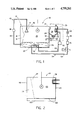
- FIG. 3 is a schematic representation, partially broken away, of still a further advantageous embodiment of a vapor generating and recovery apparatus of the present invention.
- FIG. 4 is a view of a vapor generating and recovery apparatus similar to that of FIG. 3 and illustrating an additional feature.
- FIGS. 1-3 each illustrate a vapor generating and recovery apparatus, generally denoted as the number 10, 110 and 210 respectively, for vaporizing and recovering a treating liquid.
- the apparatus can be used, for example, for cleaning objects of oil, grease, wax or particulate matter, or for heat treating an object for shock testing or metal reflow.
- FIG. 1 illustrates a vapor generating and recovery apparatus 10 including a housing 12 having sapced apart side walls 14 and 16, spaced apart end walls 18 and 20, and a floor 22.
- a partition wall 24 is located in the interior of the housing between the end walls 18 and 20 spanning the distance between the side walls 14 and 16, thus, dividing the housing interior into a liquid vaporizing chamber 16 and a vapor condensing chamber 28.
- a liquid thermal mass 30 is disposed within the liquid vaporizing chamber 26 and forms a pool to a predetermined depth covering the floor 22 of the vaporizing chamber 26.
- the liquid thermal mass can be, for example, an eutectic metal having an eutectic point, i.e. its lowest melting temperature, lower than the vaporizing temperature of the liquid to be vaporized.
- Other liquid thermal masses for example, includes silicone oils, vegetable oil, mineral oil and the like.
- the apparatus 10 further includes heating means, generally denoted as the number 32, located in the vaporizing chamber 26 below the top surface of the thermal mass 30 for heating the thermal mass 30 to at least a temperature above the vapor temperature of the liquid.
- the heating means 32 comprises at least one heat emitting coil, such as, for example, a condensing coil of a refrigerant system, generally denoted as the number 34.
- the condensing chamber 28 is formed with a condensate reservoir 31 formed in its floor.
- the condensate reservoir 31 is in liquid flow communication with the condensing chamber 28 by means of, for example, a condensate conduit 33 which transports condensate 36 from the condensate reservoir 31 to the vaporizing chamber 26 above the top surface of the thermal mass 30.
- the flow of condensate 36 can be controlled by means of a valve 35 located in the condensate conduit 33.
- the valve 35 can be activated in response to a pressure or temperature sensor 37 located in the vapor above the reservoir 31 in the condensing chamber 28.
- the apparatus 10 is also illustrated as including means, generally denoted as the numeral 42, for recirculating a quantity of the thermal mass 30 in the vaporizing chamber 26 and applying the recirculated mass into the vapor above the top surface of the thermal mass 30.
- the thermal mass recirculating means 42 includes a conduit 44 having an inlet end in the vaporizing chamber 26 below the top surface of the thermal mass 30, and an outlet end located above the operating level of the zone of vapor in the chamber 26.
- a dispersion means such as, for example, a spray head 46, is attached at the outlet end of the conduit 44 to break up the recirculated thermal mass exiting the conduit to disperse and direct the recirculated thermal mass generally down over and through the vapor zone.
- a pump 48 such as, for example, a magnetic pump which uses a magnetic flux to move the thermal mass 30, is located in the conduit 44 for pumping the thermal mass through the conduit 44 and out of the dispersion spray head 46.
- the vapor is heated from beneath by the thermal mass 30 and from above by recirculated thermal mass passing downwardly through the vapor from the dispersion spray head 46.
- the apparatus 10 also has a vapor condensing means, generally denoted as the number 38, located in the vapor condensing chamber 28 for cooling the vapor to a temperature below the vaporizing temperature causing it to condense in the condensing chamber.
- the condensing means 38 is shown as being located below the top edge of the weir 24 in the vapor zone of the vaporized liquid.
- the condensing means is shown as comprising at least one heat absorbing coil. As illustrated, the heat absorbing coil is a refrigerant evaporating coil of the refrigerant system 34.
- the refrigerant system 34 is shown as including a refrigerant compressor 50 for compressing a suitable refrigerant.
- the high pressure side of the refrigerant compressor 50 is in refrigerant flow communication with the refrigerant condensing coil 32 through a refrigerant gas conduit 52.
- the refrigerant evaporator coil 38 is located downstream of the refrigerant consensing coil 32 and is in refrigerant flow communication with the refrigerant condensing coil 32 through a conduit 54.
- a conventional refrigerant receiver 56, dryer 58 and appropriate thermal expansion valve 60 are also operatively disposed in the conduit 54 between the refrigerant condensing coil 32 and the refrigerant vaporating coil 38.
- a supplementary refrigerant condensing coil 61 can also be located in the conduit 54 between the refrigerant condensing coil 32 and refrigerant condensing coil 32 and refrigerant evaporator coil 38 to remove excess heat from the refrigerant if required.
- the heating means 32 heats the thermal mass 30 in the vaporizing chamber 26 to a temperature above the vaporizing temperature of the treating liquid.
- the thermal mass 30, in turn, transfers heat to the treating liquid being transferred from the condensing chamber 28 to the vaporizing chamber 26 causing the treating liquid to vaporize.
- the relatively large surface area and high temperature of the thermal mass 30 results in rapid heat transfer from the thermal mass 30 to the treating liquid.
- the treating liquid vapor may be cooled below its vaporizing temperature when objects "A" to be treated are initially immersed in the treating vapor, the treating liquid condensate will be substantially immediately reheated to its vaporizing temperature with a minimum amount of time lost to the surface treating process.
- the vapor rises from the vaporizing chamber 26, it migrates toward the vapor zone over the condensing chamber 28 whereat it is condensed by the cooling means 38 to a temperature below the vaporizing temperature of the treating liquid and is collected in the condensing chamber 28.
- FIG. 2 illustrates another advantageous embodiment of a vapor generating and recovery apparatus, generally denoted as the number 110, which has a number of features in common with the apparatus 10 of FIG. 1.
- the apparatus 110 includes a housing 112 having side walls 114 and 116, end walls 118 and 120, and a floor 122 cooperating to define a vaporizing and condensing chamber 126.
- Heating means 132 such as, for example, an electrical resistance heater, is located beneath and in contact with the housing floor 122. The heat energy generated by the heating means 132 is transferred to the housing floor 122 and is sufficient to heat the housing floor 122 to a temperature above the vaporizing temperature of the vaporized liquid in the chamber 126. Therefore, the housing floor functions as a thermal mass.
- the apparatus 110 also includes vapor condensing means such as cooling means 138 in the chamber 126 at a predetermined location above the housing floor 122 for condensing the vapor back toward the housing floor 122.
- the cooling means 138 can be virtually any type, for example, a cold water circulation coil or a refrigerant evaporator coil of a refrigerant system.
- the cooling means cools the vapor to a temperature below the vaporizing temperature causing the vapor to condense and fall back to the housing floor 122.
- the heated housing floor 122 functions as a thermal mass which substantially instantaneously vaporizes any liquid which comes into contact with it. Therefore, as the condensate contacts the housing floor 122 the condensate is substantially instantaneously vaporized.
- the cooling means 138 condenses the rising vapors for revaporization upon contact with the thermal mass of the housing floor 122 and prevents vapors from escaping from the chamber 126. The result is that a zone of vapor is continuously maintained from the top surface of the thermal mass housing floor 122 toward the cooling means 138.
- FIG. 3 illustrates a further advantageous embodiment of a vapor generating and recovery apparatus 210 including a housing 212 having spaced apart side walls 214 and 216, spaced apart end walls 218 and 220, and a floor 222.
- a partition wall 224 is located in the interior of the housing 212 between the end walls 218 and 220 spanning the distance between the side wall 214 and 216.
- the partition wall 224 cooperates with the end wall 218 to define a liquid vaporizing chamber 226 therebetween and cooperates with the end wall 220 to define a vapor condensing chamber 228 therebetween.
- the partition wall 224 extends above the housing floor 222 to a predetermined height.
- the bottom edge of the partition wall 224 is spaced a predetermined distance above the housing floor 222, that is, the partition wall 224 does not extend to the housing floor 222. As shown, the housing floor 222 is recessed to form a reservoir 223.
- the reservoir 223 occupies most of the floor area in the vaporizing chamber 226 and a portion of the floor area in the condensing chamber 228.
- a thermal mass 30 is located in the apparatus 210 for maintaining vaporization of the treating liquid.
- the thermal mass 30 covers the floor area in the vaporizing chamber 226 and at least a portion of the floor area in the condensing chamber 228. As shown, the thermal mass is located in the reservoir 223.
- the thermal mass 30 is illustrated as being electrically heated by, for example, electric resistance coil 232 located within the thermal mass 30.
- the apparatus 210 also has a vapor cooling means, generally denoted as the numeral 238, shown as being located over the vapor condensing chamber 228 above the top edge of the partition wall 224 in the zone of vapor for cooling the liquid vapor to a temperature below the vaporizing temperature and causing the vapor to condense and fall into the condensing chamber 228.
- the cooling means comprises at least one heat absorbing coil.
- the heat absorbing coil can be of virtually any type, but is shown for the sake of illustration as a water cooled coil through which relatively cool water flows.
- the partition wall 224 not only separates the vaporizing chamber 226 from the condensing chamber 228, but further functions as a weir for controlling the return of condensate from the condensing chamber 228 to the vaporizing chamber 226.
- the partition wall 224 is of a predetermined height such that when the level of condensate 236 in the condensing chamber 228 reaches the top edge of the partition wall 224, the condensate 236 will flow over the top edge of the partition wall into vaporizing chamber 226.
- the heating means 232 heats the thermal mass 30 in the vaporizing chamber 226 to a temperature above the vaporizing temperature of the treating liquid.
- the treating liquid vapor may be cooled below its vaporizing temperature when objects "A" to be treated are initially immersed in the treating vapor, the treating liquid condensate will be substantially immediately re-heated to its vaporizing temperature upon contact with the top surface of the thermal mass 30.
- FIG. 4 illustrates a vapor generating and recovery apparatus 210 substantially identical to the appearance 210 of FIG. 3 and includes the additional feature of a contaminate removal means. Contaminants from the items "A" being treated in the apparatus 210 may collect on the top surface of the thermal mass 30, and if allowed to build-up, act as an insulation reducing the heat transfer rate from the thermal mass 30 to the condensate falling back to the top surface of the thermal mass. Therefore, the apparatus 210 shown in FIG.
- skimming means for maintaining the top heat transfer surface of the thermal mass 30 clean and, therefore, providing for the direct heating of the vapor in the vaporizing chamber 226 as well as the substantially immediate vaporizing of any condensate falling on the top surface of the thermal mass 30.
- the skimming means 240 comprises a plurality of doctor blades 242 attached to a continuous conveyor device 244.
- the conveyor device 244 is located over the top surface of the thermal mass 30 in the vaporizing chamber 226 such that the tip of the doctor blades 242 on the bottom flight just penetrates the top surface of the thermal mass 30.
- the bottom conveyor flight moves, it causes the doctor blades 242 to skim the contaminants from the top surface of the thermal mass 30.
- the doctor blades 242 move the contaminants along the top surface of the thermal mass 30 toward and into a contaminant storage bin 246 in the housing wall 218 for disposal.
Landscapes
- Chemical & Material Sciences (AREA)
- Chemical Kinetics & Catalysis (AREA)
- Engineering & Computer Science (AREA)
- Mechanical Engineering (AREA)
- General Chemical & Material Sciences (AREA)
- Materials Engineering (AREA)
- Metallurgy (AREA)
- Organic Chemistry (AREA)
- Vaporization, Distillation, Condensation, Sublimation, And Cold Traps (AREA)
Abstract
An apparatus for vaporizing a liquid and condensing the vapor includes at least one chamber in which the liquid is vaporized and in which the vaporized liquid is condensed. The vaporizing chamber contains a heat emitting device providing a surface temperature above the vapor temperature for substantially instantaneously vaporizing the liquid condensate maintaining a predetermined vapor level in the vaporizing chamber, and a heat absorbing device for condensing the vaporized liquid.
Description
This is a continuation of application Ser. No. 581,545, filed Feb. 21, 1984, now abandoned.
1. Field of the Invention
This invention relates to a vapor generating and recovering apparatus for vaporizing a liquid and maintaining the vaporized liquid in a vapor state in a container having an open top, and more particularly, to such an apparatus using a hot surface for substantially vaporizing immediately all of a condensed vapor.
2. Description of the Prior Art
Vapor generating and recovery apparatuses are well known for use in surface treating various objects. The surface treating can be a cleaning treatment wherein foreign material, such as, for example, oil or wax is removed from the surface of the object, or a recovery treatment wherein a contaminated chemical is purified by distillation, or a heat emitting treatment for shrink fitting, or a heat absorbing treatment for reflowing metals. Regardless of the exact nature of the surface treatment, the objects to be surface treated are, typically, immersed into a vapor of an appropriate surface treating material. As the liquid boils, the vapor is recovered for reuse in the treating process.
In some instances, objects to be surface treated are at a sufficiently low temperature relative to the temperature of the vaporized liquid. When these relatively cold objects are immersed in the vapor, the objects initially and rapidly absorb enough heat from the treatment vapor to condense this vapor to a liquid. When this happens, the vapor zone collapses. The time required for revaporizing the liquid is lost to the treatment process thereby extending the time required to complete the treatment operation. This lost time increases costs, particularly when the treatment process is a step in a high volume manufacturing operation.
One example of a heretofore known apparatus is taught in U.S. Pat. No. 3,947,240 issued on Mar. 30, 1976. The apparatus is for generating a vapor for soldering, fusing or brazing articles. The apparatus includes an open topped vessel having a heating coil in the portion end and cooling coils between the top and bottom of the vessel. An eutectic solder heated by the heating coil forms a molten pool over the bottom of the vessel. A liquid to be vaporized forms a pool floating or forming a stratified layer of liquid on top of the molten pool of eutectic solder. The liquid is brought to and maintained at a boil by the heat of the molten solder which acts as a heat transfer medium between the heating coil and the liquid.
The present invention is directed to a vapor generating and recovery apparatus which provides for the substantially instantaneous vaporization of liquid back to a vapor.
More particularly, the present invention provides a vapor generating and recovery apparatus comprising a housing having at least one chamber, a thermal mass disposed within the at least one chamber; a vaporized liquid; heating means for heating the thermal mass such that the top surface will be at a temperature higher than the vapor temperature of liquid to be vaporized, said heating means being sufficient to vaporize any of said liquid coming in contact therewith; and, cooling means located in the vapor zone for condensing the vaporized liquid.
A better understanding of the present invention will be had upon reference to the following description in conjunction with the drawings wherein like numerals refer to like parts and in which:
FIG. 1 is a schematic representation, partially broken away, of an advantageous embodiment of a vapor generating and recovery apparatus of the present invention;
FIG. 2 is a schematic representation, partially broken away, of another advantageous embodiment of a vapor generating and recovery apparatus of the present invention;
FIG. 3 is a schematic representation, partially broken away, of still a further advantageous embodiment of a vapor generating and recovery apparatus of the present invention; and,
FIG. 4 is a view of a vapor generating and recovery apparatus similar to that of FIG. 3 and illustrating an additional feature.
FIGS. 1-3 each illustrate a vapor generating and recovery apparatus, generally denoted as the number 10, 110 and 210 respectively, for vaporizing and recovering a treating liquid. The apparatus can be used, for example, for cleaning objects of oil, grease, wax or particulate matter, or for heat treating an object for shock testing or metal reflow. These examples, however, are given only by way of illustrating some end uses of the apparatus and are not to be considered in any way as limitations of the present invention. For this reason, the apparatus has virtually endless applications, and the composition of the liquid will, of course, depend upon a particular end use.
FIG. 1 illustrates a vapor generating and recovery apparatus 10 including a housing 12 having sapced apart side walls 14 and 16, spaced apart end walls 18 and 20, and a floor 22. A partition wall 24 is located in the interior of the housing between the end walls 18 and 20 spanning the distance between the side walls 14 and 16, thus, dividing the housing interior into a liquid vaporizing chamber 16 and a vapor condensing chamber 28.
A liquid thermal mass 30 is disposed within the liquid vaporizing chamber 26 and forms a pool to a predetermined depth covering the floor 22 of the vaporizing chamber 26. The liquid thermal mass can be, for example, an eutectic metal having an eutectic point, i.e. its lowest melting temperature, lower than the vaporizing temperature of the liquid to be vaporized. Other liquid thermal masses, for example, includes silicone oils, vegetable oil, mineral oil and the like.
The apparatus 10 further includes heating means, generally denoted as the number 32, located in the vaporizing chamber 26 below the top surface of the thermal mass 30 for heating the thermal mass 30 to at least a temperature above the vapor temperature of the liquid. The heating means 32, as illustrated, comprises at least one heat emitting coil, such as, for example, a condensing coil of a refrigerant system, generally denoted as the number 34.
As shown in FIG. 1, the condensing chamber 28 is formed with a condensate reservoir 31 formed in its floor. The condensate reservoir 31 is in liquid flow communication with the condensing chamber 28 by means of, for example, a condensate conduit 33 which transports condensate 36 from the condensate reservoir 31 to the vaporizing chamber 26 above the top surface of the thermal mass 30. The flow of condensate 36 can be controlled by means of a valve 35 located in the condensate conduit 33. The valve 35 can be activated in response to a pressure or temperature sensor 37 located in the vapor above the reservoir 31 in the condensing chamber 28.
The apparatus 10 is also illustrated as including means, generally denoted as the numeral 42, for recirculating a quantity of the thermal mass 30 in the vaporizing chamber 26 and applying the recirculated mass into the vapor above the top surface of the thermal mass 30. As shown, the thermal mass recirculating means 42 includes a conduit 44 having an inlet end in the vaporizing chamber 26 below the top surface of the thermal mass 30, and an outlet end located above the operating level of the zone of vapor in the chamber 26. A dispersion means such as, for example, a spray head 46, is attached at the outlet end of the conduit 44 to break up the recirculated thermal mass exiting the conduit to disperse and direct the recirculated thermal mass generally down over and through the vapor zone. A pump 48 such as, for example, a magnetic pump which uses a magnetic flux to move the thermal mass 30, is located in the conduit 44 for pumping the thermal mass through the conduit 44 and out of the dispersion spray head 46. Thus, the vapor is heated from beneath by the thermal mass 30 and from above by recirculated thermal mass passing downwardly through the vapor from the dispersion spray head 46.
The apparatus 10 also has a vapor condensing means, generally denoted as the number 38, located in the vapor condensing chamber 28 for cooling the vapor to a temperature below the vaporizing temperature causing it to condense in the condensing chamber. The condensing means 38 is shown as being located below the top edge of the weir 24 in the vapor zone of the vaporized liquid. The condensing means is shown as comprising at least one heat absorbing coil. As illustrated, the heat absorbing coil is a refrigerant evaporating coil of the refrigerant system 34.
By way of example, the refrigerant system 34 is shown as including a refrigerant compressor 50 for compressing a suitable refrigerant. The high pressure side of the refrigerant compressor 50 is in refrigerant flow communication with the refrigerant condensing coil 32 through a refrigerant gas conduit 52. The refrigerant evaporator coil 38 is located downstream of the refrigerant consensing coil 32 and is in refrigerant flow communication with the refrigerant condensing coil 32 through a conduit 54. A conventional refrigerant receiver 56, dryer 58 and appropriate thermal expansion valve 60 are also operatively disposed in the conduit 54 between the refrigerant condensing coil 32 and the refrigerant vaporating coil 38. A supplementary refrigerant condensing coil 61 can also be located in the conduit 54 between the refrigerant condensing coil 32 and refrigerant condensing coil 32 and refrigerant evaporator coil 38 to remove excess heat from the refrigerant if required.
The heating means 32 heats the thermal mass 30 in the vaporizing chamber 26 to a temperature above the vaporizing temperature of the treating liquid. The thermal mass 30, in turn, transfers heat to the treating liquid being transferred from the condensing chamber 28 to the vaporizing chamber 26 causing the treating liquid to vaporize. The relatively large surface area and high temperature of the thermal mass 30 results in rapid heat transfer from the thermal mass 30 to the treating liquid. Thus, as the treating liquid vapor may be cooled below its vaporizing temperature when objects "A" to be treated are initially immersed in the treating vapor, the treating liquid condensate will be substantially immediately reheated to its vaporizing temperature with a minimum amount of time lost to the surface treating process.
As the vapor rises from the vaporizing chamber 26, it migrates toward the vapor zone over the condensing chamber 28 whereat it is condensed by the cooling means 38 to a temperature below the vaporizing temperature of the treating liquid and is collected in the condensing chamber 28.
FIG. 2 illustrates another advantageous embodiment of a vapor generating and recovery apparatus, generally denoted as the number 110, which has a number of features in common with the apparatus 10 of FIG. 1.
The apparatus 110 includes a housing 112 having side walls 114 and 116, end walls 118 and 120, and a floor 122 cooperating to define a vaporizing and condensing chamber 126. Heating means 132 such as, for example, an electrical resistance heater, is located beneath and in contact with the housing floor 122. The heat energy generated by the heating means 132 is transferred to the housing floor 122 and is sufficient to heat the housing floor 122 to a temperature above the vaporizing temperature of the vaporized liquid in the chamber 126. Therefore, the housing floor functions as a thermal mass.
The apparatus 110 also includes vapor condensing means such as cooling means 138 in the chamber 126 at a predetermined location above the housing floor 122 for condensing the vapor back toward the housing floor 122. The cooling means 138 can be virtually any type, for example, a cold water circulation coil or a refrigerant evaporator coil of a refrigerant system. The cooling means cools the vapor to a temperature below the vaporizing temperature causing the vapor to condense and fall back to the housing floor 122.
In operation, the heated housing floor 122 functions as a thermal mass which substantially instantaneously vaporizes any liquid which comes into contact with it. Therefore, as the condensate contacts the housing floor 122 the condensate is substantially instantaneously vaporized. The cooling means 138 condenses the rising vapors for revaporization upon contact with the thermal mass of the housing floor 122 and prevents vapors from escaping from the chamber 126. The result is that a zone of vapor is continuously maintained from the top surface of the thermal mass housing floor 122 toward the cooling means 138.
FIG. 3 illustrates a further advantageous embodiment of a vapor generating and recovery apparatus 210 including a housing 212 having spaced apart side walls 214 and 216, spaced apart end walls 218 and 220, and a floor 222. A partition wall 224 is located in the interior of the housing 212 between the end walls 218 and 220 spanning the distance between the side wall 214 and 216. The partition wall 224 cooperates with the end wall 218 to define a liquid vaporizing chamber 226 therebetween and cooperates with the end wall 220 to define a vapor condensing chamber 228 therebetween. It should be noted that the partition wall 224 extends above the housing floor 222 to a predetermined height. The bottom edge of the partition wall 224 is spaced a predetermined distance above the housing floor 222, that is, the partition wall 224 does not extend to the housing floor 222. As shown, the housing floor 222 is recessed to form a reservoir 223. The reservoir 223 occupies most of the floor area in the vaporizing chamber 226 and a portion of the floor area in the condensing chamber 228.
A thermal mass 30 is located in the apparatus 210 for maintaining vaporization of the treating liquid. The thermal mass 30 covers the floor area in the vaporizing chamber 226 and at least a portion of the floor area in the condensing chamber 228. As shown, the thermal mass is located in the reservoir 223. The thermal mass 30 is illustrated as being electrically heated by, for example, electric resistance coil 232 located within the thermal mass 30.
The apparatus 210 also has a vapor cooling means, generally denoted as the numeral 238, shown as being located over the vapor condensing chamber 228 above the top edge of the partition wall 224 in the zone of vapor for cooling the liquid vapor to a temperature below the vaporizing temperature and causing the vapor to condense and fall into the condensing chamber 228. The cooling means comprises at least one heat absorbing coil. The heat absorbing coil can be of virtually any type, but is shown for the sake of illustration as a water cooled coil through which relatively cool water flows.
In the illustrated vapor generating and recovery apparatus 210, the partition wall 224 not only separates the vaporizing chamber 226 from the condensing chamber 228, but further functions as a weir for controlling the return of condensate from the condensing chamber 228 to the vaporizing chamber 226. The partition wall 224 is of a predetermined height such that when the level of condensate 236 in the condensing chamber 228 reaches the top edge of the partition wall 224, the condensate 236 will flow over the top edge of the partition wall into vaporizing chamber 226.
The heating means 232 heats the thermal mass 30 in the vaporizing chamber 226 to a temperature above the vaporizing temperature of the treating liquid. Thus, as the treating liquid vapor may be cooled below its vaporizing temperature when objects "A" to be treated are initially immersed in the treating vapor, the treating liquid condensate will be substantially immediately re-heated to its vaporizing temperature upon contact with the top surface of the thermal mass 30.
FIG. 4 illustrates a vapor generating and recovery apparatus 210 substantially identical to the appearance 210 of FIG. 3 and includes the additional feature of a contaminate removal means. Contaminants from the items "A" being treated in the apparatus 210 may collect on the top surface of the thermal mass 30, and if allowed to build-up, act as an insulation reducing the heat transfer rate from the thermal mass 30 to the condensate falling back to the top surface of the thermal mass. Therefore, the apparatus 210 shown in FIG. 4 embodies a contaminate removal means exemplified as skimming means, generally denoted as the numeral 240, for maintaining the top heat transfer surface of the thermal mass 30 clean and, therefore, providing for the direct heating of the vapor in the vaporizing chamber 226 as well as the substantially immediate vaporizing of any condensate falling on the top surface of the thermal mass 30. As illustrated, the skimming means 240 comprises a plurality of doctor blades 242 attached to a continuous conveyor device 244. The conveyor device 244 is located over the top surface of the thermal mass 30 in the vaporizing chamber 226 such that the tip of the doctor blades 242 on the bottom flight just penetrates the top surface of the thermal mass 30. Thus, as the bottom conveyor flight moves, it causes the doctor blades 242 to skim the contaminants from the top surface of the thermal mass 30. The doctor blades 242 move the contaminants along the top surface of the thermal mass 30 toward and into a contaminant storage bin 246 in the housing wall 218 for disposal.
The foregoing detailed description is given primarily for clearness of understanding of the present invention and no unnecessary limitations are to be understood therefrom for modifications will become obvious to those skilled in the art upon reading this disclosure and may be made without departing from the spirit of the invention or scope of the appended claims.
Claims (14)
1. A method of vaporizing a liquid and condensing the vapor in a vapor generating and recovery apparatus used to surface treat an object having a vaporizing chamber and a condensing chamber separated from the vaporizing chamber and in both liquid and vapor flow communication with the vaporizing chamber, comprising the steps of:
heating a thermal mass at the bottom of the vaporizing chamber only to a temperature sufficiently
higher than the vaporizing temperature of the liquid to be vaporized to substantially immediately vaporize any of the liquid coming in contact therewith;
contacting the thermal mass with the liquid thereby substantially immediately vaporizing the liquid;
surface treating an object immersed in the vaporized liquid in the vaporizing chamber while allowing the vaporized liquid to flow from the vaporizing chamber into the condensing chamber;
condensing the vaporized liquid in the condensing chamber;
returning the condensed liquid from the condensing chamber directly to the vaporizing chamber; and,
contacting the thermal mass with the condensed liquid thereby substantially immediately vaporizing the liquid.
2. The method of claim 1, wherein the thermal mass is a pool of liquid.
3. The method of claim 2, wherein the liquid is an eutectic metal.
4. The method of claim 2, wherein the liquid is an oil.
5. The method of claim 2, further comprising the steps of:
removing a portion of the liquid thermal mass from the pool of liquid thermal mass; and,
passing the removed portion of the liquid thermal mass downwardly through the vaporized liquid rising from the pool of thermal mass liquid and back into the pool of thermal mass liquid.
6. The method of claim 1, wherein the thermal mass is solid.
7. The method of claim 1, further comprising the step of skimming the top surface of the thermal mass to remove contaminants therefrom.
8. A method for vaporizing a liquid and condensing the vapor in a vapor generating and recovery apparatus used to surface treat an object having a vaporizing chamber and a condensing chamber separated from the vaporizing chamber and in both liquid and vapor flow communication with the vaporizing chamber, comprising the steps of:
heating a thermal mass at the bottom of the vaporizing chamber only to a temperature sufficiently higher than the vaporizing temperature of the liquid to be vaporized to substantially immediately vaporize any liquid coming in contact with the top surface of the thermal mass;
contacting the top surface of the thermal mass with the liquid whereupon the liquid is substantially immediately vaporized;
surface treating an object immersed in the vaporized liquid in the vaporizing chamber while allowing the vaporized liquid to flow from the vaporizing chamber into the condensing chamber;
condensing the vaporized liquid in the condensing chamber;
returning the condensing liquid from the condensing chamber directly to the vaporizing chamber; and,
contacting the top surface of the thermal mass with the returned liquid whereupon the condensed liquid is substantially immediately vaporized.
9. The method of claim 8, further comprising the step of skimming the top surface of the thermal mass to remove contaminants therefrom.
10. The method of claim 8, wherein the thermal mass is a pool of liquid.
11. The method of claim 10, wherein the liquid is an eutectic metal.
12. The method of claim 10, wherein the liquid is an oil.
13. The method of claim 8, wherein the thermal mass is solid.
14. The method of claim 10, further comprising the steps of:
removing a portion of the liquid thermal mass from the pool of liquid thermal mass; and,
passing the removed portion of the liquid thermal mass downwardly through the vaporized liquid rising from the pool of thermal mass liquid and back into the pool of thermal mass liquid.
Priority Applications (1)
| Application Number | Priority Date | Filing Date | Title |
|---|---|---|---|
| US07/000,038 US4755261A (en) | 1984-02-21 | 1987-01-02 | Vapor generating and recovery method for vapor retention and reuse |
Applications Claiming Priority (2)
| Application Number | Priority Date | Filing Date | Title |
|---|---|---|---|
| US58154584A | 1984-02-21 | 1984-02-21 | |
| US07/000,038 US4755261A (en) | 1984-02-21 | 1987-01-02 | Vapor generating and recovery method for vapor retention and reuse |
Related Parent Applications (1)
| Application Number | Title | Priority Date | Filing Date |
|---|---|---|---|
| US58154584A Continuation | 1984-02-21 | 1984-02-21 |
Publications (1)
| Publication Number | Publication Date |
|---|---|
| US4755261A true US4755261A (en) | 1988-07-05 |
Family
ID=26667155
Family Applications (1)
| Application Number | Title | Priority Date | Filing Date |
|---|---|---|---|
| US07/000,038 Expired - Fee Related US4755261A (en) | 1984-02-21 | 1987-01-02 | Vapor generating and recovery method for vapor retention and reuse |
Country Status (1)
| Country | Link |
|---|---|
| US (1) | US4755261A (en) |
Cited By (27)
| Publication number | Priority date | Publication date | Assignee | Title |
|---|---|---|---|---|
| US5051135A (en) * | 1989-01-30 | 1991-09-24 | Kabushiki Kaisha Tiyoda Seisakusho | Cleaning method using a solvent while preventing discharge of solvent vapors to the environment |
| US5075982A (en) * | 1990-09-25 | 1991-12-31 | Allied-Signal Inc. | Open top defluxer with improved solvent vapor recovery |
| US5090431A (en) * | 1990-06-01 | 1992-02-25 | K & M Electronics, Inc. | Cleaning apparatus with vapor containment system |
| EP0481474A1 (en) * | 1990-10-18 | 1992-04-22 | Ettore Alagna | Machine for washing mechanical pieces with volatile solvents |
| US5346534A (en) * | 1990-09-12 | 1994-09-13 | Baxter International Inc. | Process for treating an article with a volatile fluid |
| US5539995A (en) * | 1994-03-16 | 1996-07-30 | Verteq, Inc. | Continuous flow vapor dryer system |
| US5549128A (en) * | 1995-02-24 | 1996-08-27 | Mansur Industries Inc. | General parts washer |
| US5669401A (en) * | 1995-09-22 | 1997-09-23 | Mansur Industries Inc. | General washer apparatus |
| US6010599A (en) * | 1995-09-20 | 2000-01-04 | American Technologies Group, Inc. | Compact vacuum distillation device |
| EP1312404A1 (en) * | 2001-11-15 | 2003-05-21 | Alexander Von Poswik | Process and apparatus to distillate water from seawater, brackish water or other contaminated waters |
| US20060260064A1 (en) * | 2005-05-23 | 2006-11-23 | Luckman Joel A | Methods and apparatus for laundering with aqueous and non-aqueous working fluid |
| US7300468B2 (en) | 2003-10-31 | 2007-11-27 | Whirlpool Patents Company | Multifunctioning method utilizing a two phase non-aqueous extraction process |
| US7513004B2 (en) | 2003-10-31 | 2009-04-07 | Whirlpool Corporation | Method for fluid recovery in a semi-aqueous wash process |
| US7513132B2 (en) | 2003-10-31 | 2009-04-07 | Whirlpool Corporation | Non-aqueous washing machine with modular construction |
| US7534304B2 (en) | 1997-04-29 | 2009-05-19 | Whirlpool Corporation | Non-aqueous washing machine and methods |
| US20090172891A1 (en) * | 2004-04-13 | 2009-07-09 | Whirlpool Corporation | Method and apparatus for cleaning objects in an automatic cleaning appliance using an oxidizing agent |
| US7695524B2 (en) | 2003-10-31 | 2010-04-13 | Whirlpool Corporation | Non-aqueous washing machine and methods |
| WO2010066002A1 (en) * | 2008-12-10 | 2010-06-17 | Kevin Stephen Davies | Method and apparatus for reflow soldering |
| US7739891B2 (en) | 2003-10-31 | 2010-06-22 | Whirlpool Corporation | Fabric laundering apparatus adapted for using a select rinse fluid |
| US7837741B2 (en) | 2004-04-29 | 2010-11-23 | Whirlpool Corporation | Dry cleaning method |
| US7966684B2 (en) | 2005-05-23 | 2011-06-28 | Whirlpool Corporation | Methods and apparatus to accelerate the drying of aqueous working fluids |
| US8262741B2 (en) | 1997-04-29 | 2012-09-11 | Whirlpool Corporation | Non-aqueous washing apparatus and method |
| CN103272797A (en) * | 2013-05-31 | 2013-09-04 | 陈春 | Method and device for cleaning workpieces |
| US20170349451A1 (en) * | 2016-06-06 | 2017-12-07 | Labstrong Corp. | Device for the Purification of Water Using a Heat Pump |
| EP3556503A1 (en) * | 2018-04-16 | 2019-10-23 | Panasonic Intellectual Property Management Co., Ltd. | Vapor-phase type heating method and vapor-phase type heating apparatus |
| US20220238478A1 (en) * | 2021-01-25 | 2022-07-28 | Infineon Technologies Ag | Arrangement for forming a connection |
| IT202100013601A1 (en) * | 2021-05-25 | 2022-11-25 | 77 Vision Way Ltd | WATER DISTILLATION DEVICE |
Citations (10)
| Publication number | Priority date | Publication date | Assignee | Title |
|---|---|---|---|---|
| US1421108A (en) * | 1919-01-03 | 1922-06-27 | Taylor Buel | Sirup boiling and skimming apparatus |
| US2976224A (en) * | 1958-01-22 | 1961-03-21 | Exxon Research Engineering Co | Vaporization by molten material |
| US3032482A (en) * | 1959-04-02 | 1962-05-01 | Richard W Shoemaker | Process of recovering fresh water from salt water with a hot heavy material |
| US3181600A (en) * | 1961-01-24 | 1965-05-04 | Fmc Corp | Liquid to liquid heat exchange |
| US3642583A (en) * | 1970-08-03 | 1972-02-15 | Anti Pollution Systems | Treatment of sewage and other contaminated liquids with recovery of water by distillation and oxidation |
| US3904102A (en) * | 1974-06-05 | 1975-09-09 | Western Electric Co | Apparatus and method for soldering, fusing or brazing |
| US3947240A (en) * | 1974-11-01 | 1976-03-30 | Western Electric Company, Inc. | Method and apparatus for generating a vapor for soldering fusing or brazing articles |
| US4210461A (en) * | 1975-06-02 | 1980-07-01 | Elecktrokemiska AB | Method for recovering heat in a vapor degreasing apparatus |
| US4394216A (en) * | 1981-12-24 | 1983-07-19 | Mccord James W | Vapor condensate return means in a vapor generating and recovery apparatus |
| US4488933A (en) * | 1982-08-27 | 1984-12-18 | Finish Engineering Company, Inc. | Small solvent recovery unit |
-
1987
- 1987-01-02 US US07/000,038 patent/US4755261A/en not_active Expired - Fee Related
Patent Citations (10)
| Publication number | Priority date | Publication date | Assignee | Title |
|---|---|---|---|---|
| US1421108A (en) * | 1919-01-03 | 1922-06-27 | Taylor Buel | Sirup boiling and skimming apparatus |
| US2976224A (en) * | 1958-01-22 | 1961-03-21 | Exxon Research Engineering Co | Vaporization by molten material |
| US3032482A (en) * | 1959-04-02 | 1962-05-01 | Richard W Shoemaker | Process of recovering fresh water from salt water with a hot heavy material |
| US3181600A (en) * | 1961-01-24 | 1965-05-04 | Fmc Corp | Liquid to liquid heat exchange |
| US3642583A (en) * | 1970-08-03 | 1972-02-15 | Anti Pollution Systems | Treatment of sewage and other contaminated liquids with recovery of water by distillation and oxidation |
| US3904102A (en) * | 1974-06-05 | 1975-09-09 | Western Electric Co | Apparatus and method for soldering, fusing or brazing |
| US3947240A (en) * | 1974-11-01 | 1976-03-30 | Western Electric Company, Inc. | Method and apparatus for generating a vapor for soldering fusing or brazing articles |
| US4210461A (en) * | 1975-06-02 | 1980-07-01 | Elecktrokemiska AB | Method for recovering heat in a vapor degreasing apparatus |
| US4394216A (en) * | 1981-12-24 | 1983-07-19 | Mccord James W | Vapor condensate return means in a vapor generating and recovery apparatus |
| US4488933A (en) * | 1982-08-27 | 1984-12-18 | Finish Engineering Company, Inc. | Small solvent recovery unit |
Cited By (35)
| Publication number | Priority date | Publication date | Assignee | Title |
|---|---|---|---|---|
| US5051135A (en) * | 1989-01-30 | 1991-09-24 | Kabushiki Kaisha Tiyoda Seisakusho | Cleaning method using a solvent while preventing discharge of solvent vapors to the environment |
| US5090431A (en) * | 1990-06-01 | 1992-02-25 | K & M Electronics, Inc. | Cleaning apparatus with vapor containment system |
| US5346534A (en) * | 1990-09-12 | 1994-09-13 | Baxter International Inc. | Process for treating an article with a volatile fluid |
| US5075982A (en) * | 1990-09-25 | 1991-12-31 | Allied-Signal Inc. | Open top defluxer with improved solvent vapor recovery |
| EP0481474A1 (en) * | 1990-10-18 | 1992-04-22 | Ettore Alagna | Machine for washing mechanical pieces with volatile solvents |
| US5539995A (en) * | 1994-03-16 | 1996-07-30 | Verteq, Inc. | Continuous flow vapor dryer system |
| US5549128A (en) * | 1995-02-24 | 1996-08-27 | Mansur Industries Inc. | General parts washer |
| US6010599A (en) * | 1995-09-20 | 2000-01-04 | American Technologies Group, Inc. | Compact vacuum distillation device |
| US5669401A (en) * | 1995-09-22 | 1997-09-23 | Mansur Industries Inc. | General washer apparatus |
| US7534304B2 (en) | 1997-04-29 | 2009-05-19 | Whirlpool Corporation | Non-aqueous washing machine and methods |
| US8262741B2 (en) | 1997-04-29 | 2012-09-11 | Whirlpool Corporation | Non-aqueous washing apparatus and method |
| EP1312404A1 (en) * | 2001-11-15 | 2003-05-21 | Alexander Von Poswik | Process and apparatus to distillate water from seawater, brackish water or other contaminated waters |
| US7695524B2 (en) | 2003-10-31 | 2010-04-13 | Whirlpool Corporation | Non-aqueous washing machine and methods |
| US7513004B2 (en) | 2003-10-31 | 2009-04-07 | Whirlpool Corporation | Method for fluid recovery in a semi-aqueous wash process |
| US7300468B2 (en) | 2003-10-31 | 2007-11-27 | Whirlpool Patents Company | Multifunctioning method utilizing a two phase non-aqueous extraction process |
| US7513132B2 (en) | 2003-10-31 | 2009-04-07 | Whirlpool Corporation | Non-aqueous washing machine with modular construction |
| US7739891B2 (en) | 2003-10-31 | 2010-06-22 | Whirlpool Corporation | Fabric laundering apparatus adapted for using a select rinse fluid |
| US20090172891A1 (en) * | 2004-04-13 | 2009-07-09 | Whirlpool Corporation | Method and apparatus for cleaning objects in an automatic cleaning appliance using an oxidizing agent |
| US7837741B2 (en) | 2004-04-29 | 2010-11-23 | Whirlpool Corporation | Dry cleaning method |
| US20060260064A1 (en) * | 2005-05-23 | 2006-11-23 | Luckman Joel A | Methods and apparatus for laundering with aqueous and non-aqueous working fluid |
| US7966684B2 (en) | 2005-05-23 | 2011-06-28 | Whirlpool Corporation | Methods and apparatus to accelerate the drying of aqueous working fluids |
| US8360305B2 (en) | 2008-12-10 | 2013-01-29 | Kevin Stephen Davies | Method and apparatus for reflow soldering |
| CN102216017A (en) * | 2008-12-10 | 2011-10-12 | 凯文·斯蒂芬·戴维斯 | Method and apparatus for reflow soldering |
| WO2010066002A1 (en) * | 2008-12-10 | 2010-06-17 | Kevin Stephen Davies | Method and apparatus for reflow soldering |
| CN102216017B (en) * | 2008-12-10 | 2014-04-09 | 凯文·斯蒂芬·戴维斯 | Method and apparatus for reflow soldering |
| AU2009326859B2 (en) * | 2008-12-10 | 2014-07-24 | Kevin Stephen Davies | Method and apparatus for reflow soldering |
| CN103272797A (en) * | 2013-05-31 | 2013-09-04 | 陈春 | Method and device for cleaning workpieces |
| CN103272797B (en) * | 2013-05-31 | 2016-08-31 | 陈春 | workpiece cleaning method and device |
| US20170349451A1 (en) * | 2016-06-06 | 2017-12-07 | Labstrong Corp. | Device for the Purification of Water Using a Heat Pump |
| EP3556503A1 (en) * | 2018-04-16 | 2019-10-23 | Panasonic Intellectual Property Management Co., Ltd. | Vapor-phase type heating method and vapor-phase type heating apparatus |
| CN110385494A (en) * | 2018-04-16 | 2019-10-29 | 松下知识产权经营株式会社 | Gas phase formula heating means and gas phase formula heating device |
| CN110385494B (en) * | 2018-04-16 | 2021-01-29 | 松下知识产权经营株式会社 | Gas phase heating method and gas phase heating device |
| US20220238478A1 (en) * | 2021-01-25 | 2022-07-28 | Infineon Technologies Ag | Arrangement for forming a connection |
| IT202100013601A1 (en) * | 2021-05-25 | 2022-11-25 | 77 Vision Way Ltd | WATER DISTILLATION DEVICE |
| WO2022249019A1 (en) * | 2021-05-25 | 2022-12-01 | 77 Vision Way Ltd | Water distillation device |
Similar Documents
| Publication | Publication Date | Title |
|---|---|---|
| US4755261A (en) | Vapor generating and recovery method for vapor retention and reuse | |
| US4090843A (en) | Apparatus for maintaining a vapor blanket in a condensation heating facility | |
| US4392049A (en) | Condensation heating apparatus and method | |
| US4217221A (en) | Oil refining apparatus | |
| US3460990A (en) | Method for cleaning objects with solvent | |
| EP0153631B1 (en) | Vapor generating and recovery process for vapor retention recovery and reuse | |
| US4615768A (en) | Vapor generating and recovery apparatus including continuous conveying means through a vapor zone | |
| CA2277449A1 (en) | Vapour management system | |
| EP0152876B1 (en) | Multi-vapor level vapor generating and recovery apparatus | |
| KR860000241B1 (en) | Process for vaporizing a liquid and condensing the vapors thereof | |
| US2575051A (en) | Process for purifying oil by distillation | |
| US4299663A (en) | Vapor generating device | |
| US5817217A (en) | Machine for confining a primary fluid by means of a secondary fluid in the vapor phase | |
| JPS61238464A (en) | Commodity heating equipment | |
| EP0152875A2 (en) | Vapor generating and recovery apparatus including continuous conveying means through a vapor zone | |
| MXPA02002438A (en) | Apparatus and method for separating mixed liquids. | |
| US4072298A (en) | Method of cooling a quenching bath of melted salt | |
| JP3500331B2 (en) | Distillation regenerator | |
| WO2021044324A1 (en) | Device for increasing metal evaporation efficiency, preferably in crucibles, in particular in alloy vacuum distillation processes | |
| US4175730A (en) | Device for cooling a quenching bath of melted salt | |
| CA2282649C (en) | Device for recovering and separating impurities from the cooling fluid of a conditioning system | |
| US4860460A (en) | Apparatus for heating articles | |
| JPH0320303B2 (en) | ||
| JPH07115171B2 (en) | Work quenching equipment in vapor phase soldering equipment | |
| GB1572751A (en) | Method of and apparatus for drying or cleaning electrically insulated components and parts thereof |
Legal Events
| Date | Code | Title | Description |
|---|---|---|---|
| REMI | Maintenance fee reminder mailed | ||
| LAPS | Lapse for failure to pay maintenance fees | ||
| FP | Lapsed due to failure to pay maintenance fee |
Effective date: 19920705 |
|
| STCH | Information on status: patent discontinuation |
Free format text: PATENT EXPIRED DUE TO NONPAYMENT OF MAINTENANCE FEES UNDER 37 CFR 1.362 |