US4755105A - Impeller improvement - Google Patents

Impeller improvement Download PDF

Info

Publication number
US4755105A
US4755105A US06/923,385 US92338586A US4755105A US 4755105 A US4755105 A US 4755105A US 92338586 A US92338586 A US 92338586A US 4755105 A US4755105 A US 4755105A
Authority
US
United States
Prior art keywords
impeller
vane
vanes
hub
housing
Prior art date
Legal status (The legal status is an assumption and is not a legal conclusion. Google has not performed a legal analysis and makes no representation as to the accuracy of the status listed.)
Expired - Fee Related
Application number
US06/923,385
Inventor
G. Allen Blakeslee
Frederick E. Coffman
Current Assignee (The listed assignees may be inaccurate. Google has not performed a legal analysis and makes no representation or warranty as to the accuracy of the list.)
Chemcut Corp
Original Assignee
Chemcut Corp
Priority date (The priority date is an assumption and is not a legal conclusion. Google has not performed a legal analysis and makes no representation as to the accuracy of the date listed.)
Filing date
Publication date
Application filed by Chemcut Corp filed Critical Chemcut Corp
Priority to US06/923,385 priority Critical patent/US4755105A/en
Assigned to CHEMCUT CORPORATION, A CORP. OF PA. reassignment CHEMCUT CORPORATION, A CORP. OF PA. ASSIGNMENT OF ASSIGNORS INTEREST. Assignors: BLAKESLEE, G. ALLEN, COFFMAN, FREDERICK E.
Priority to GB08706039A priority patent/GB2196700A/en
Priority to DE19873709231 priority patent/DE3709231A1/en
Priority to FR8705010A priority patent/FR2605684A1/en
Priority to JP62103397A priority patent/JPS63113199A/en
Priority to IT8720349A priority patent/IT1205103B/en
Application granted granted Critical
Publication of US4755105A publication Critical patent/US4755105A/en
Anticipated expiration legal-status Critical
Expired - Fee Related legal-status Critical Current

Links

Images

Classifications

    • FMECHANICAL ENGINEERING; LIGHTING; HEATING; WEAPONS; BLASTING
    • F04POSITIVE - DISPLACEMENT MACHINES FOR LIQUIDS; PUMPS FOR LIQUIDS OR ELASTIC FLUIDS
    • F04DNON-POSITIVE-DISPLACEMENT PUMPS
    • F04D27/00Control, e.g. regulation, of pumps, pumping installations or pumping systems specially adapted for elastic fluids
    • FMECHANICAL ENGINEERING; LIGHTING; HEATING; WEAPONS; BLASTING
    • F04POSITIVE - DISPLACEMENT MACHINES FOR LIQUIDS; PUMPS FOR LIQUIDS OR ELASTIC FLUIDS
    • F04DNON-POSITIVE-DISPLACEMENT PUMPS
    • F04D29/00Details, component parts, or accessories
    • F04D29/26Rotors specially for elastic fluids
    • F04D29/28Rotors specially for elastic fluids for centrifugal or helico-centrifugal pumps for radial-flow or helico-centrifugal pumps
    • F04D29/281Rotors specially for elastic fluids for centrifugal or helico-centrifugal pumps for radial-flow or helico-centrifugal pumps for fans or blowers
    • FMECHANICAL ENGINEERING; LIGHTING; HEATING; WEAPONS; BLASTING
    • F04POSITIVE - DISPLACEMENT MACHINES FOR LIQUIDS; PUMPS FOR LIQUIDS OR ELASTIC FLUIDS
    • F04DNON-POSITIVE-DISPLACEMENT PUMPS
    • F04D29/00Details, component parts, or accessories
    • F04D29/26Rotors specially for elastic fluids
    • F04D29/28Rotors specially for elastic fluids for centrifugal or helico-centrifugal pumps for radial-flow or helico-centrifugal pumps
    • F04D29/30Vanes
    • F04D29/305Flexible vanes

Abstract

An impeller is provided that is adapted to be rotationally driven, and which is constructed of a resiliently stretchable elastomeric material, such that, with increased centrifugal force that is applied to the impeller vanes with increased rotation of the impeller, the impeller increases in diameter and provides increased output performance beyond the output performance of a non-stretchable impeller of the same general size as the impeller at rest.

Description

BACKGROUND OF THE INVENTION
In the impeller art, and specifically in the art of blower impellers, it is known to rotate an impeller within a housing to generate air flow from the housing in order to perform various functions. For example, in U.S. Pat. No. 4,017,982, the disclosure of which is herein incorporated by reference, an air blower is utilized for providing a high volume of air flow, that may or not be heated, for drying printed circuit boards, often in a somewhat corrosive atmosphere. In instances where corrosive substances might be encountered by a blower, blower components, and the impeller itself, and even more specifically, the vanes of the impeller, may be constructed of various materials that are adapted to withstand corrosive environments. Such materials can be metals such as stainless steel, or can be synthetic materials such as polyvinylchloride.
It is also known that impellers, fans, propellers and the like may be constructed of softer materials, such as rubber, for the purpose of preventing damage to the hand of a user, such as in the case of an open bladed fan, as in U.S. Pat. No. 2,123,146, or in the case of U.S. Pat. No. 2,182,161.
It is additionally known that fan blades can change in shape with rotation as in U.S. Pat. No. 3,759,630 or 4,177,012, or in pitch, as in U.S. Pat. No. 4,187,055. Furthermore, it is known that propellers, blades and the like, can be extended in length, radially outwardly with rotation, by various mechanical mechanisms, such as in U.S. Pat. Nos. 2,079,942 and 3,814,351.
SUMMARY OF THE INVENTION
The present invention is directed to increasing the output performance of an impeller, and the blower or other device utilizing the impeller, by constructing the impeller of a material that is sufficiently flexible and elastic within the elastic limit of the material, that the impeller will stretch radially outwardly with increased rotation, to provide delivery of increased flow volume per unit time and/or output flow pressure, relative to a non-stretchable impeller of the same general diameter at rest.
Accordingly, it is a primary object of this invention to provide an improved impeller.
It is a further object of this invention to provide an improved blower or other device utilizing an improved impeller.
Other objects and advantages of the present invention will be readily apparent to those skilled in the art from a reading of the following brief descriptions of the drawing figures, the detailed descriptions of the preferred embodiments, and the amended claims.
BRIEF DESCRIPTIONS OF THE DRAWING FIGURES
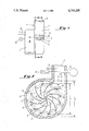
FIG. 1 is a side elevational view of a motor driven blower, taken looking from the right side of FIG. 2, utilizing an impeller in accordance with this invention, with a portion of the blower housing being broken away for the sake of clarity, to illustrate the "cupping" of an impeller vane therein when rotated at a sufficient speed to effect the same.
FIG. 2 is a vertical sectional view, taken through the blower housing of FIG. 1, and wherein the impeller is shown in full lines in its rest configuration, and with the impeller also being framentally illustrated in phantom in its "stretched" configuration, along with certain measuring instruments being schematically illustrated.
DETAILED DESCRIPTIONS OF THE PREFERRED EMBODIMENTS
Referring now to the drawings in detail, reference is first made to FIG. 1, wherein a blower motor assembly is generally designated by the numeral 10, as in including a blower 11 and a motor 12, with the motor being connected to the housing 13 of the blower 11, in a conventional manner, and with the rotor (not shown) of the motor 12 being connected to the impeller 14 of the blower 11, also in a conventional manner for rotation of the impeller 14 in the counter-clockwise direction of the arrow 15 illustrated in FIG. 2.
The housing 13 will conventionally have air inlets, such as suitable openings, not shown in the wall 16 thereof, and will have a discharge end for air output at 17.
The impeller 14 will generally have a central hub 20 about which a plurality of vanes 21 are disposed, extending in a general outward radial direction from a generally central portion of the impeller at or near the hub 20, to their tips 22, although preferably in arcuate configuration such as that shown for the vanes in FIG. 2. The vanes are generally connected by suitable web portions 23, generally planar in arrangement, with the vanes 21 extending outwardly on each side of the web portions 23, as for example in the general arrangement illustrated in FIG. 1 for the fragmentally open portion of the housing, with the vanes extending axially rightward and leftward as viewed in FIG. 1.
It will be noted that as used herein, the term "impeller" is used in the broadest generic sense, to encompass various propellers, rotors and the like. Similarly, the term "vane" as used herein is intended to encompass blades and like devices adapted to work on fluid media.
The impeller, and especially its vanes, and generally its various web portions as well, are constructed of a material that is capable of stretching in use and then returning to its original configuration. That is, the material is of a generally flexible elastomeric material that is sufficiently extensible within its elastic limit that, in use, the impeller may be rotated such that sufficient centrifugal force is generated to cause the impeller, and especially its vanes, to "grow" along the lines illustrated in FIG. 2, from the full line positions therefor, to the phantom line positions illustrated therefor, such that the impeller generally grows from an original diameter D1, to a stretched diameter D2, as illustrated in FIG. 2.
While the impeller 14 hereof is described as being of a flexible elastomeric stretchable material, it will be understood that certain portions, for example, such as radial innermost portions such as the hub, may be constructed of other materials, such as metal or plastic materials, that may be used to securely fasten the impeller to the rotor of a motor, in that such portions of the impeller need not stretch to perform in accordance with the present invention.
The stretchable parts of the impeller (such as the vanes and the web) have been found to function desirably when the material of construction is a polyurethane. It has also been found that the softer the urethane, the greater is the elastic growth under the centrifugal force conditions of rotation. For example, a polyurethane material having a Shore durometer hardness of 80A underwent a stretching or growth of about 2 inches in diameter, over and above the diameter D1 and 14 inches at rest, for a final diameter D2 of 16 inches at a speed of rotation of 3450 revolutions per minute. Under similar conditions, another, somewhat harder, polyurethane material, with a Shore A durometer hardness of 90, resulted in an increase in diameter of about 11/8 inches, under the same other general conditions. Still another polyurethane material, even harder, with a Shore D durometer hardness of 55, underwent a diameter growth of about 3/16 inches, again, under the same general conditions.
The polyurethane impeller discussed above having an 80A Shore hardness had a specific gravity of 1.13, an ultimate tensile strength of 5500 pounds per square inch, an ultimate elongation prior to rupture of 550 percent, and tensile modulus in pounds per square inch of 550, 700 and 1600 at elongations of 50%, 100% and 300%, respectively. The polyurethane impeller discussed above having a 90A Shore hardness had a specific gravity of 1.14, an ultimate tensile strength of 6200 pounds per square inch, an ultimate elongation prior to rupture of 430 percent, and a tensile modulus in pounds per square inch of 1100, 1530 and 3400 at elongations of 50%, 100%, and 30%, respectively. The polyurethane impeller discussed above having a 55D Shore hardness had a specific gravity of 1.15, an ultimate tensile strength of 6500 pounds per square inch, an ultimate elongation prior to rupture of 400 percent, and a tensile modulus in pounds per square inch of 1950, 2600 and 4900 at elongations of 50%, 100% and 300%, respectively.
Comparison tests were made between a non-stretchable standard 14 inch molded 12 vane impeller of polyvinylchloride construction, as compared with a 14 inch molded 12 vane impeller of polyurethane construction, with the comparison results in terms of output performance, specifically as measured in terms of operating pressure at output, and the volume of flow in cubic feet per minute, being as indicated on the charts produced below. In each case, the cross-sectional area of the discharge end was varied from 0 to 0.0483 square feet to get optimum operating pressure and output volume per unit of time as shown. The operating pressure at the discharge end is measured by a manometer or any other suitable means. The velocity is the peak air velocity at the discharge end.
__________________________________________________________________________
          1   2   3   4   5   6   7   8                                   
__________________________________________________________________________
STANDARD NON-STRETCHING IMPELLER                                          
Area (Sq. Ft.)                                                            
          0   .0069                                                       
                  .0138                                                   
                      .0207                                               
                          .0276                                           
                              .0345                                       
                                  .0414                                   
                                      .0483                               
Static Pressure                                                           
          113/4+                                                          
(In. of H.sub.2 O)                                                        
Operating Pressure                                                        
              113/4+                                                      
                  12+ 121/2                                               
                          121/2                                           
                              12  113/4                                   
                                      111/2                               
(In. of H.sub.2 O)                                                        
Velocity      13726                                                       
                  13871                                                   
                      14157                                               
                          14157                                           
                              13871                                       
                                  13726                                   
                                      13579                               
(Ft./Min.)                                                                
Volume (CFM)  94.7                                                        
                  191.4                                                   
                      293 390.7                                           
                              478.5                                       
                                  568.3                                   
                                      655.8                               
STRETCHING IMPELLER (Shore 80A Hardness)                                  
Area (Sq. Ft.)                                                            
          0   .0069                                                       
                  .0138                                                   
                      .0207                                               
                          .0276                                           
                              .0345                                       
                                  .0414                                   
                                      .0483                               
Static Pressure                                                           
          141/2                                                           
(In. of H.sub.2 O)                                                        
Operating Pressure                                                        
              141/2                                                       
                  143/4                                                   
                      151/4                                               
                          151/2                                           
                              15  143/4                                   
                                      141/2                               
(In. of H.sub.2 O)                                                        
Velocity      15248                                                       
                  15379                                                   
                      15637.6                                             
                          15765                                           
                              15508                                       
                                  15379                                   
                                      15248                               
(Ft./Min.)                                                                
Volume (CFM)  105.2                                                       
                  212.2                                                   
                      323 435 535 636.7                                   
                                      736.5                               
__________________________________________________________________________
As the charts above demonstrate, the output in terms of flow per unit time, and the operating pressure associated with that output, are substantially greater for the stretching impeller that is the subject of the present invention, than for a non-stretching standard impeller.
Additionally, impellers in accordance with the present invention have been found to provide excellent flexing life, very good chemical resistance, high physical strength, better resistance to temperature than with standard polyvinylchloride impellers, and a wide range of hardness.
With reference again to the illustrations of FIGS. 1 and 2, it will be seen that, when the motor 12 is rotated by means of suitable electrical attachments, as at 25, to a source of electric power, a rotation of the motor will provide a rotation which enables the centrifugal force that is generated to cause the impeller to grow. In making tests of the type discussed above, the motor speed may be controlled by a suitable tachometer, schematically shown at 26. Additionally, the output pressure of air being delivered by the impeller 14 through discharge lines 17 may be measured my means of a suitable manometer 29, disposed in the air stream as illustrated in FIG. 2, in a conventional manner or by any other conventional pressure measuring device. Additionally, the volume of flow produced per unit of time, such as in CFM may be measured by a suitable volume measuring device 27, likewise disposed in the air stream toward discharge 17, as illustrated. The velocity of air may be measured by any suitable velocity-determining device 29.
It will be noted from FIG. 1 that the vanes "cup" in an opposite (upward) direction to that which would be expected considering the resistance they would encounter from the fluid medium in which they are working; namely, air. This is due to the effect of centrifugal force on their oppositely extending edges 19 which substantially overcomes the air resistance.
It will be apparent that impellers and especially impeller vanes in accordance with this invention may be made of various elastomeric flexible materials that have the ability to stretch during use, as described above, with the ability to regain their original shape and size thereafter. Additionally, it will be apparent that various constructions of vanes or blades for impellers, propellers, rotors or the like may be also be made within the spirit and scope of the invention. Similarly, the impellers may be used with or without various housings, and may work with air, liquid, or various fluid media depending upon the circumstances of use, all within the spirit and scope of the invention.

Claims (12)

What is claimed is:
1. An impeller adapted to be rotationally driven and having a generally central hub and at least one vane extending radially outwardly and being carried by the hub, with the vane being comprised of a generally flexible elastomeric material that is sufficiently extensible within its elastic limit that the vane stretches radially outwardly along its length, to have greater length under the centrifugal force of impeller rotation.
2. The impeller of claim 1, wherein the vane is generally parallel to the axis of the hub, connected thereto by a web portion with the vane additionally being sufficiently elastically flexible that it reconfigures from a linear-like configuration and assumes a cup-like configuration under the centrifugal force of impeller rotation.
3. The impeller of claim 1, wherein at least one web is provided, connecting the vane and hub, and wherein the web is sufficiently extensible within its elastic limit, that the web stretches radially outwardly under the centrifugal force of impeller rotation.
4. The impeller of claim 3, wherein the web is generally planar in radial disposition.
5. An impeller adapted to be rotationally driven from a hub, and having a generally central hub and a plurality of vanes extending radially outwardly of and being carried by the hub, and terminating in vane tips, with the vanes being comprised of a generally flexible elastomeric material that is sufficiently extensible within its elastic limit that the vanes stretch radially outwardly along its length, to have a greater length when the impeller is rotationally driven such that:
(a) a surface of revolution defined by the tips of the vanes when the impeller is rotationally driven is of a greater diameter than the surface of revolution defined by the vane tips when the impeller is at rest; and
(b) the impeller output performance increases with the increase in diameter of the surface of revolution of the vane tips when rotationally driven.
6. The impeller of claim 5, wherein the impeller is disposed in a housing, with the housing having a housing discharge, and wherein the vane material is sufficiently stretchable that the output performance increases in flow volume per unit of time of flow through the discharge, with the increase in diameter of the surface of revolution.
7. The impeller of claim 6, wherein the impeller is disposed in a housing, and that the housing having a housing discharge, and wherein the vane material is sufficiently stretchable that the output performance increases in output flow pressume at discharge, with the increase in diameter of the surface of revolution.
8. The impeller of claim 5, wherein the impeller is disposed in a housing discharge, and wherein the vane material is sufficiently stretchable that the output performance increases in output flow pressure at discharge, with the increase in diameter of the surface of revolution.
9. The impeller of claim 5, wherein the vanes are disposed generally parallel to the axis of the hub, connected thereto by suitable correction portions.
10. The impeller of claim 5, wherein at least the vanes thereof are made of a polyurethane material.
11. The impeller of claim 5, wherein there are a plurality of webs connecting the vanes and hubs and wherein the webs are sufficiently extensible within their elastic limit that the webs stretch radially outwardly under the centrifugal force of impeller rotation.
12. The impeller of claim 11, wherein the webs are generally planar in radial disposition.
US06/923,385 1986-10-27 1986-10-27 Impeller improvement Expired - Fee Related US4755105A (en)

Priority Applications (6)

Application Number Priority Date Filing Date Title
US06/923,385 US4755105A (en) 1986-10-27 1986-10-27 Impeller improvement
GB08706039A GB2196700A (en) 1986-10-27 1987-03-13 Elastomeric impeller
DE19873709231 DE3709231A1 (en) 1986-10-27 1987-03-20 WHEEL
FR8705010A FR2605684A1 (en) 1986-10-27 1987-04-09 IMPROVED FAN WHEEL
JP62103397A JPS63113199A (en) 1986-10-27 1987-04-28 Impeller
IT8720349A IT1205103B (en) 1986-10-27 1987-04-30 REVOLVING IMPELLER STRUCTURE, IN PARTICULAR FOR USE IN BLOWER EQUIPMENT

Applications Claiming Priority (1)

Application Number Priority Date Filing Date Title
US06/923,385 US4755105A (en) 1986-10-27 1986-10-27 Impeller improvement

Publications (1)

Publication Number Publication Date
US4755105A true US4755105A (en) 1988-07-05

Family

ID=25448608

Family Applications (1)

Application Number Title Priority Date Filing Date
US06/923,385 Expired - Fee Related US4755105A (en) 1986-10-27 1986-10-27 Impeller improvement

Country Status (6)

Country Link
US (1) US4755105A (en)
JP (1) JPS63113199A (en)
DE (1) DE3709231A1 (en)
FR (1) FR2605684A1 (en)
GB (1) GB2196700A (en)
IT (1) IT1205103B (en)

Cited By (11)

* Cited by examiner, † Cited by third party
Publication number Priority date Publication date Assignee Title
US5711657A (en) * 1994-07-15 1998-01-27 Oase-Pumpen Wuebker Soehne Gmbh & Co. Maschinenfabrik Centrifugal pump, particularly for fountains
US6003195A (en) * 1997-12-02 1999-12-21 Woodland Power Products, Inc. Vacuum generation device
US6685446B2 (en) * 2000-07-06 2004-02-03 Askoll Holding S.R.L. Monodirectional impeller with flexible vanes
US20090209401A1 (en) * 2008-02-20 2009-08-20 Northern Plastics Ltd. Flapper roll
WO2010048288A1 (en) 2008-10-21 2010-04-29 Ibalance Medical, Inc. Method and apparatus for performing and open wedge, high tibial osteotomy
US9689264B2 (en) 2013-03-15 2017-06-27 Regal Beloit America, Inc. Centrifugal fan impeller with variable shape fan blades and method of assembly
AU2013263811B2 (en) * 2012-12-03 2018-03-15 Angelo Lambrinos Notaras Motorised Portable Blower Apparatus
CN107939724A (en) * 2017-12-28 2018-04-20 沈志伟 A kind of impeller and the vortex device with the impeller
EP3236079B1 (en) 2008-12-05 2020-10-21 ECP Entwicklungsgesellschaft mbH Fluid pump with a rotor
US11181119B2 (en) * 2018-04-20 2021-11-23 Johnson Electric International AG Impeller and water pump having the same
US20210402118A1 (en) * 2018-10-05 2021-12-30 Tecnicas Biomedicas Para La Salud, S.L. Driving device for providing assisted ventilation

Families Citing this family (4)

* Cited by examiner, † Cited by third party
Publication number Priority date Publication date Assignee Title
JP2873581B2 (en) * 1988-12-05 1999-03-24 一男 黒岩 Centrifugal compressor
AT413743B (en) 2001-11-08 2006-05-15 Tcg Unitech Ag RADIAL PUMP
WO2008038306A2 (en) * 2006-09-28 2008-04-03 Weir Minerals India Private Limited An improved ceramic integral vanes impeller
JP4583435B2 (en) 2007-12-19 2010-11-17 株式会社三菱東京Ufj銀行 stand

Citations (20)

* Cited by examiner, † Cited by third party
Publication number Priority date Publication date Assignee Title
US815738A (en) * 1904-12-05 1906-03-20 Henry B Prosser Propeller for boats.
US2079942A (en) * 1935-05-13 1937-05-11 Velle Clarence W Le Folding electric fan
US2123146A (en) * 1936-08-07 1938-07-05 Chicago Electric Mfg Co Rubber bladed fan
US2182161A (en) * 1938-04-07 1939-12-05 Jubilce Mfg Co Flexible fan
US2646261A (en) * 1950-06-23 1953-07-21 Eugene M Poirot Device which aerates water
US2669188A (en) * 1950-03-14 1954-02-16 Patent Dev Company Pump impeller
US2737373A (en) * 1952-09-29 1956-03-06 Clifford B Kinley Mechanical agitator
US2979288A (en) * 1959-01-15 1961-04-11 Klein Albert Aircraft propeller arrangement and means for elongating same
GB874531A (en) * 1959-12-31 1961-08-10 Aei Hotpoint Ltd Centrifugal pump impeller with variable blade
US3734638A (en) * 1970-11-06 1973-05-22 Rockwell Mfg Co Flexible vane turbine pump
US3759630A (en) * 1972-04-24 1973-09-18 Wallace Murray Corp Flexible bladed fan with improved reinforcing
US3814251A (en) * 1972-08-09 1974-06-04 Sperry Rand Corp Power transmission
US3938260A (en) * 1974-12-11 1976-02-17 Whirlpool Corporation Adjustable baffle for appliance
US4008985A (en) * 1974-02-14 1977-02-22 U.S. Philips Corporation Pumping device for fluids
US4177012A (en) * 1978-03-15 1979-12-04 Fram Corporation Fan blade with bends forming general blade curvature
US4187055A (en) * 1978-04-03 1980-02-05 Vernco Corporation Flexible fan
US4347038A (en) * 1979-04-20 1982-08-31 Aisin Seiki Kabushiki Kaisha Flexible blade fan
US4393650A (en) * 1977-04-20 1983-07-19 Rolls-Royce Limited Gas turbine engine having an automatic ice shedding spinner
GB2114675A (en) * 1982-02-10 1983-08-24 Do Politekh Inst Centrifugal fan impeller
US4595338A (en) * 1983-11-17 1986-06-17 Piezo Electric Products, Inc. Non-vibrational oscillating blade piezoelectric blower

Family Cites Families (1)

* Cited by examiner, † Cited by third party
Publication number Priority date Publication date Assignee Title
GB2214675B (en) * 1988-03-28 1991-09-04 C & N Electrical Ind Ltd Programmable beacon

Patent Citations (20)

* Cited by examiner, † Cited by third party
Publication number Priority date Publication date Assignee Title
US815738A (en) * 1904-12-05 1906-03-20 Henry B Prosser Propeller for boats.
US2079942A (en) * 1935-05-13 1937-05-11 Velle Clarence W Le Folding electric fan
US2123146A (en) * 1936-08-07 1938-07-05 Chicago Electric Mfg Co Rubber bladed fan
US2182161A (en) * 1938-04-07 1939-12-05 Jubilce Mfg Co Flexible fan
US2669188A (en) * 1950-03-14 1954-02-16 Patent Dev Company Pump impeller
US2646261A (en) * 1950-06-23 1953-07-21 Eugene M Poirot Device which aerates water
US2737373A (en) * 1952-09-29 1956-03-06 Clifford B Kinley Mechanical agitator
US2979288A (en) * 1959-01-15 1961-04-11 Klein Albert Aircraft propeller arrangement and means for elongating same
GB874531A (en) * 1959-12-31 1961-08-10 Aei Hotpoint Ltd Centrifugal pump impeller with variable blade
US3734638A (en) * 1970-11-06 1973-05-22 Rockwell Mfg Co Flexible vane turbine pump
US3759630A (en) * 1972-04-24 1973-09-18 Wallace Murray Corp Flexible bladed fan with improved reinforcing
US3814251A (en) * 1972-08-09 1974-06-04 Sperry Rand Corp Power transmission
US4008985A (en) * 1974-02-14 1977-02-22 U.S. Philips Corporation Pumping device for fluids
US3938260A (en) * 1974-12-11 1976-02-17 Whirlpool Corporation Adjustable baffle for appliance
US4393650A (en) * 1977-04-20 1983-07-19 Rolls-Royce Limited Gas turbine engine having an automatic ice shedding spinner
US4177012A (en) * 1978-03-15 1979-12-04 Fram Corporation Fan blade with bends forming general blade curvature
US4187055A (en) * 1978-04-03 1980-02-05 Vernco Corporation Flexible fan
US4347038A (en) * 1979-04-20 1982-08-31 Aisin Seiki Kabushiki Kaisha Flexible blade fan
GB2114675A (en) * 1982-02-10 1983-08-24 Do Politekh Inst Centrifugal fan impeller
US4595338A (en) * 1983-11-17 1986-06-17 Piezo Electric Products, Inc. Non-vibrational oscillating blade piezoelectric blower

Cited By (14)

* Cited by examiner, † Cited by third party
Publication number Priority date Publication date Assignee Title
US5711657A (en) * 1994-07-15 1998-01-27 Oase-Pumpen Wuebker Soehne Gmbh & Co. Maschinenfabrik Centrifugal pump, particularly for fountains
US6003195A (en) * 1997-12-02 1999-12-21 Woodland Power Products, Inc. Vacuum generation device
US6685446B2 (en) * 2000-07-06 2004-02-03 Askoll Holding S.R.L. Monodirectional impeller with flexible vanes
US20040136848A1 (en) * 2000-07-06 2004-07-15 Askoll Holdings S.R.L. Monodirectional impeller with flexible vanes
US6988873B2 (en) * 2000-07-06 2006-01-24 Askoll Holding S.R.L. Monodirectional impeller with flexible vanes
US20090209401A1 (en) * 2008-02-20 2009-08-20 Northern Plastics Ltd. Flapper roll
WO2010048288A1 (en) 2008-10-21 2010-04-29 Ibalance Medical, Inc. Method and apparatus for performing and open wedge, high tibial osteotomy
EP3236079B1 (en) 2008-12-05 2020-10-21 ECP Entwicklungsgesellschaft mbH Fluid pump with a rotor
AU2013263811B2 (en) * 2012-12-03 2018-03-15 Angelo Lambrinos Notaras Motorised Portable Blower Apparatus
US9689264B2 (en) 2013-03-15 2017-06-27 Regal Beloit America, Inc. Centrifugal fan impeller with variable shape fan blades and method of assembly
CN107939724A (en) * 2017-12-28 2018-04-20 沈志伟 A kind of impeller and the vortex device with the impeller
CN107939724B (en) * 2017-12-28 2023-12-29 沈志伟 Impeller and vortex device with same
US11181119B2 (en) * 2018-04-20 2021-11-23 Johnson Electric International AG Impeller and water pump having the same
US20210402118A1 (en) * 2018-10-05 2021-12-30 Tecnicas Biomedicas Para La Salud, S.L. Driving device for providing assisted ventilation

Also Published As

Publication number Publication date
JPS63113199A (en) 1988-05-18
FR2605684A1 (en) 1988-04-29
DE3709231A1 (en) 1988-04-28
GB8706039D0 (en) 1987-04-15
IT1205103B (en) 1989-03-15
IT8720349A0 (en) 1987-04-30
GB2196700A (en) 1988-05-05

Similar Documents

Publication Publication Date Title
US4755105A (en) Impeller improvement
US4063852A (en) Axial flow impeller with improved blade shape
US4543041A (en) Impellor for centrifugal compressor
EP1087146A3 (en) Impeller for fan, fan using the same, and air conditioner using the same
US8100664B2 (en) Impeller for a cooling fan
US7008189B2 (en) Centrifugal fan
BRPI0711849A2 (en) axial fan assembly
US3263909A (en) High-efficiency fan assembly for vacuum cleaner
US20020076323A1 (en) Air blower
GB2455553A (en) Axial flow fan motor mounting
US4483659A (en) Axial flow impeller
EP1512918A3 (en) Axial flow fan
US9599126B1 (en) Noise abating impeller
KR970000161A (en) cleaner
CA2063586A1 (en) Fan for an electrically operated machine
KR20040026882A (en) Axial Flow Fan
CN112752908A (en) Air circulator with double rotary wings
KR100463543B1 (en) Spiral Fan Assembly
JP2002364592A (en) Fan for agricultural machine
JPS5835298A (en) Wind channel of blower
KR100273357B1 (en) Sirocoo fan
KR100487377B1 (en) Spiral Fan
GB2342123A (en) Fan blade extension member
JPH0436096A (en) Impeller for axial flow blower
JPH0315697A (en) Impeller of axial blower

Legal Events

Date Code Title Description
AS Assignment

Owner name: CHEMCUT CORPORATION, 500 SCIENCE PARK ROAD, STATE

Free format text: ASSIGNMENT OF ASSIGNORS INTEREST.;ASSIGNORS:BLAKESLEE, G. ALLEN;COFFMAN, FREDERICK E.;REEL/FRAME:004633/0473

Effective date: 19861023

Owner name: CHEMCUT CORPORATION, A CORP. OF PA.,PENNSYLVANIA

Free format text: ASSIGNMENT OF ASSIGNORS INTEREST;ASSIGNORS:BLAKESLEE, G. ALLEN;COFFMAN, FREDERICK E.;REEL/FRAME:004633/0473

Effective date: 19861023

REMI Maintenance fee reminder mailed
LAPS Lapse for failure to pay maintenance fees
FP Lapsed due to failure to pay maintenance fee

Effective date: 19920705

STCH Information on status: patent discontinuation

Free format text: PATENT EXPIRED DUE TO NONPAYMENT OF MAINTENANCE FEES UNDER 37 CFR 1.362