US4748815A - Steam turbine system - Google Patents

Steam turbine system Download PDF

Info

Publication number
US4748815A
US4748815A US07/083,447 US8344787A US4748815A US 4748815 A US4748815 A US 4748815A US 8344787 A US8344787 A US 8344787A US 4748815 A US4748815 A US 4748815A
Authority
US
United States
Prior art keywords
steam
turbine
pressure
condenser
exhaust
Prior art date
Legal status (The legal status is an assumption and is not a legal conclusion. Google has not performed a legal analysis and makes no representation as to the accuracy of the status listed.)
Expired - Fee Related
Application number
US07/083,447
Inventor
Alfred Junior
Walter Aumann
Current Assignee (The listed assignees may be inaccurate. Google has not performed a legal analysis and makes no representation or warranty as to the accuracy of the list.)
Koerting Hannover GmbH
Original Assignee
Koerting Hannover GmbH
Priority date (The priority date is an assumption and is not a legal conclusion. Google has not performed a legal analysis and makes no representation as to the accuracy of the date listed.)
Filing date
Publication date
Application filed by Koerting Hannover GmbH filed Critical Koerting Hannover GmbH
Assigned to KORTING HANNOVER reassignment KORTING HANNOVER ASSIGNMENT OF ASSIGNORS INTEREST. Assignors: AUMANN, WALTER, JUNIOR, ALFRED
Application granted granted Critical
Publication of US4748815A publication Critical patent/US4748815A/en
Anticipated expiration legal-status Critical
Expired - Fee Related legal-status Critical Current

Links

Images

Classifications

    • FMECHANICAL ENGINEERING; LIGHTING; HEATING; WEAPONS; BLASTING
    • F28HEAT EXCHANGE IN GENERAL
    • F28BSTEAM OR VAPOUR CONDENSERS
    • F28B9/00Auxiliary systems, arrangements, or devices
    • F28B9/10Auxiliary systems, arrangements, or devices for extracting, cooling, and removing non-condensable gases
    • FMECHANICAL ENGINEERING; LIGHTING; HEATING; WEAPONS; BLASTING
    • F01MACHINES OR ENGINES IN GENERAL; ENGINE PLANTS IN GENERAL; STEAM ENGINES
    • F01KSTEAM ENGINE PLANTS; STEAM ACCUMULATORS; ENGINE PLANTS NOT OTHERWISE PROVIDED FOR; ENGINES USING SPECIAL WORKING FLUIDS OR CYCLES
    • F01K9/00Plants characterised by condensers arranged or modified to co-operate with the engines
    • F01K9/02Arrangements or modifications of condensate or air pumps

Definitions

  • the invention concerns an extraction type steam turbine system having an improved, more efficient means for removing gases from the condensate.
  • the publication mentioned discloses combinations of steam jet compressors and connected suction pumps for the purpose of suction.
  • the drive steam for the steam jet compressor is supplied from a bleeder on the turbine, the pressure of which, during all operating conditions of the turbine, lies above atmospheric pressure. This means that a relatively high power requirement is needed to operate the steam jet compressor.
  • German patent specification No. 514 718 single and multiple stage steam jet vacuum pumps are described, which compress up to atmospheric pressure, and are connected on the motive steam end, to an extraction point on the turbine.
  • only those extraction lines can be used, which, during all operating conditions of the steam turbine, lie above atmospheric pressure.
  • a relatively high power requirement is necessary for operation.
  • This intermediate heat exchanger is, on the water end, so connected into the feed water cycle, that it lies downstream of the main condensate pump, and upstream of the first feed water heater. It serves partially to heat condensate prior to the first feed water heater.
  • the total bleeder steam flow heats the condensate partially in the intermediate heat exchanger as first stage of feed water heating by means of motive steam of the steam jet compressor (this is bleeder steam) and by means of suction steam from the condenser (this is recovered heat energy) and partially in the first feed water heater to a preset nominal value.
  • this new bleed steam flow is thereby reduced by a portion of steam the heat energy of which corresponds to that of the suction steam flow from the condenser. This portion of the bleeder steam no longer required for the feed water heating flows through the end stages of the turbine, so that a corresponding portion of the energy is regained.
  • the effective power requirement will vary, depending on the pressure and the temperature of the motive steam used for the steam jet compressor. The power requirement is lower when the pressure and temperature of motive steam are lower and larger when the steam flow is suctioned from the turbine condenser. It is always taken as the starting point in the prior art that the motive steam pressure is above atmospheric pressure, so that a considerable power requirement is needed for effecting the suction.
  • the object of the invention is to provide a steam turbine plant or system of the type described, the overall efficiency of which is greater than that of the steam turbine systems described in the prior art.
  • the basic concept of the invention lies in taking a portion of the bleeder steam from the extraction point with the lowest bleeder pressure (next to the exhaust point of the turbine) as the motive steam for the steam jet compressor.
  • the bleeder steam was used solely in the steam turbine cycle for preheating of condensate or feed water.
  • a heat exchanger connects to the exhaust line (compression end) of the jet compressor for preheating condensate pumped from the condenser.
  • the bleeder steam not only preheats the condensate, but additionally powers the compressor. Through this, the overall efficiency of the steam turbine device is increased.
  • the drive end of the steam jet compressor is connected to the extraction point without the interposition of a pressure regulator, that is to say, the drive steam pressure in the steam line flowing to the compressor depends solely on the turbine load, and changes correspondingly.
  • the suction devices are usually constructed in steam turbine devices in accordance with guidelines which are different in different countries. Examples of such guidelines are, for example, the following:
  • the jet compressor is dimensionsed so that the outlet pressure of the jet compressor, that is, the pressure in the heat exchanger is at least 25%, preferably more than 50%, of the bleeder steam pressure, so that the steam suction flow from the condenser is at a maximum.
  • the increased steam suction power improves the flow conditions in the turbine condenser, and reduces the gas partial pressure, and thereby the oxygen partial pressure as well.
  • the invention is illustrated in greater detail in the example of execution depicted in the drawing showing a flow chart for a steam turbine plant constructed in accordance with the invention.
  • a boiler 1 is connected by means of a line 2 with a high-pressure stage 3 of a steam turbine 4.
  • the turbine has a plurality of extraction points 5, 8, 9, 12, 13 and the exhaust point 14.
  • Point 5 is connected with a middle pressure stage 7 by means of a line 6.
  • Stage 7 has two extraction points 8, 9, the latter being connected with a low pressure stage 11 by means of a line 10.
  • Stage 11 has extraction points 12, 13, and the exhaust point 14.
  • Shaft 15 of the steam turbine 4 is connected to an electrical generator 16.
  • the exhaust point 14 is the exhaust end of the steam turbine 4, and is connected with a condenser 18 by means of a line 17 in which the exhaust steam is condensed in the known manner.
  • the circulating medium flowing through condenser 18 is e.g. air cooled by means of a cooling tower 19.
  • the condensate from the condenser 18 goes through a line 20, a condensate pump 21, a heat exchanger 22, as well as through feed water heaters 23 through 27, and a feed water pump 28, and then back into the boiler 1.
  • a suction line 29 leads to the suction end of a steam jet compressor 30 to draw gases and steam from the condenser.
  • the motive end of the compressor is fed through lines 31, 32, which connects with the extraction point 13, which is the extraction point having the lowest bleeder steam pressure except for the exhaust pressure at the exhaust point 14.
  • a portion of bleeder steam from line 32 flows through line 39 to first feed water heater 23.
  • the pressure at the extraction point 13, during the different operational conditions of the steam turbine unit, lies continuously or temporarily below atmospheric.
  • the motive end of the steam jet compressor 30 is therefore fed with a partial flow of the bleeder steam from the extraction point 13.
  • the compression or exhaust end of the steam jet compressor 30 is connected with the heat exchanger 22 by means of a line 33.
  • This heat exchanger lies ina line 34 downstream behind the condenser 18 between condensate pump 21 and the first feed water heater 23.
  • a suction pump 36 is connected to the heat exchanger 22 by means of a suction line 35.
  • This pump can be a water ring pump, a water jet pump, a steam jet pump, or a combination of these.
  • the outlet 37 connects with the atmosphere.

Abstract

An extraction turbine system in which the condenser connects to a venting system to remove non-condensing air flows penetrating the system and gases entrained in the steam and condensate and a portion of exhaust steam. The venting system has a steam jet compressor to provide the suction for removing the gases and steam. The motive end of the compressor is fed by a steam line connecting to the lowest pressure extraction point on the turbine (next to the turbine exhaust point), which pressure is below atmospheric. This construction reduces the power requirement for removing the gases and steam; it recovers heat energy from the steam exhausted from the turbine, preheats the condensate, and correspondingly gains additional mechanical energy from the turbine.

Description

The invention concerns an extraction type steam turbine system having an improved, more efficient means for removing gases from the condensate.
PRIOR ART
It is generally known to ventilate condensers in steam turbine plants. Various methods for ventilation are known, for example, from the article "Wirtschaftliche Entluftung von Dampfturbinenkondensatoren" ("Economical Ventilation of Steam Turbine Condensers"), by A. Junior in the publication of the firm Korting Hannover AG, dated 1978. Ventilation has the goal of removing infiltrated air from the vacuum side of the steam turbine. Despite the most painstaking sealing of part joints, shaft seals, connecting flanges, and despite a flawless execution of all welding seams, it is unavoidable that small air flows penetrate the system. Also, the steam brings some air and other gases along with it. These non-condensing components must be suctioned off from the condenser, so that the greatest possible power with a given steam turbine device can be attained.
The publication mentioned discloses combinations of steam jet compressors and connected suction pumps for the purpose of suction. The drive steam for the steam jet compressor is supplied from a bleeder on the turbine, the pressure of which, during all operating conditions of the turbine, lies above atmospheric pressure. This means that a relatively high power requirement is needed to operate the steam jet compressor.
In German patent specification No. 514 718, single and multiple stage steam jet vacuum pumps are described, which compress up to atmospheric pressure, and are connected on the motive steam end, to an extraction point on the turbine. Here, too, however, only those extraction lines can be used, which, during all operating conditions of the steam turbine, lie above atmospheric pressure. Thus, a relatively high power requirement is necessary for operation.
In the article by A. Junior, "Die Dampfstrahl-Vakuum-pumpe als Warmepumpe bei der Evakuierung eines Dampfturbinenkondensators" ("The Steam Jet Vacuum Pump as a Heat Pump in the Evacuation of a Steam Turbine Condenser"), in the periodical "Kraftwerkstechnik" ("Power Plant Technology"), September 1985, pages 829-835, it is described that, in a steam turbine device, a heat exchanger is usually connected between the steam jet compressor and the suction pump, in which heat exchanger the motive and suction steam flowing from the steam jet compressor condense. This intermediate heat exchanger is, on the water end, so connected into the feed water cycle, that it lies downstream of the main condensate pump, and upstream of the first feed water heater. It serves partially to heat condensate prior to the first feed water heater. The total bleeder steam flow heats the condensate partially in the intermediate heat exchanger as first stage of feed water heating by means of motive steam of the steam jet compressor (this is bleeder steam) and by means of suction steam from the condenser (this is recovered heat energy) and partially in the first feed water heater to a preset nominal value. Compared to the original total bleed steam flow, this new bleed steam flow is thereby reduced by a portion of steam the heat energy of which corresponds to that of the suction steam flow from the condenser. This portion of the bleeder steam no longer required for the feed water heating flows through the end stages of the turbine, so that a corresponding portion of the energy is regained.
The energy expended for the steam jet compressor and suction pump, reduced by this regained portion of the energy, is the effective energy or power, expended for the suction. The effective power requirement will vary, depending on the pressure and the temperature of the motive steam used for the steam jet compressor. The power requirement is lower when the pressure and temperature of motive steam are lower and larger when the steam flow is suctioned from the turbine condenser. It is always taken as the starting point in the prior art that the motive steam pressure is above atmospheric pressure, so that a considerable power requirement is needed for effecting the suction.
THE INVENTION
The object of the invention is to provide a steam turbine plant or system of the type described, the overall efficiency of which is greater than that of the steam turbine systems described in the prior art.
The basic concept of the invention lies in taking a portion of the bleeder steam from the extraction point with the lowest bleeder pressure (next to the exhaust point of the turbine) as the motive steam for the steam jet compressor. In prior systems, the bleeder steam was used solely in the steam turbine cycle for preheating of condensate or feed water. In accordance with the invention, a heat exchanger connects to the exhaust line (compression end) of the jet compressor for preheating condensate pumped from the condenser. Thus, the bleeder steam not only preheats the condensate, but additionally powers the compressor. Through this, the overall efficiency of the steam turbine device is increased. The pressure of this bleeder steam during the different operating conditions of the steam turbine device, continuously or temporarily, lies below atmospheric pressure.
No additional power, therefore, is needed for the opeation of the steam jet compressor; that is, the effective power requirement for the steam jet compressor is evaluated as zero.
In one particularly economical arrangement the drive end of the steam jet compressor is connected to the extraction point without the interposition of a pressure regulator, that is to say, the drive steam pressure in the steam line flowing to the compressor depends solely on the turbine load, and changes correspondingly.
The suction devices are usually constructed in steam turbine devices in accordance with guidelines which are different in different countries. Examples of such guidelines are, for example, the following:
Germany: "Empfehlung fur Auslegung und Betrieb von Vakuum-pumpen bei Dampfturbinen-Kondensatoren" ("Recommendation for the Construction and Operation of Vacuum Pumps in Steam Turbine Condensers"), VGB-R 126 L, 2nd revised edition, 1986, issued by the VGB Technische Vereinigung der Grosskraftwerksbetriebe, which can be obtained from: VGB-Kraftwerkstechnik, Klinkestrabe 27-31, D-4300 Essen.
U.S.A.: "Standards for Steam Surface Condensers", Seventh Edition, Copyright Jan. 1, 1978, by: Heat Exchange Institute, 1230 Keith Building, Cleveland, OH, 44115.
Great "Recommended Practice for the Design of Surface Type Steam Britain: Condensing Plant", Publication No. 222, 1967: The British Electrical and Allied Manufacturers' Association (Incorporated), 8 Leicester Street, London WC2.
It is the objective of all these guidelines to determine a minimum size of the suction stream for the size of each turbine plant in order to ensure a flawless condensation process. This objective was achieved in the previouslyknown devices, only by means of additional power consumption.
It is surprising that, in accordance with the invention, namely, using bleeder steam from the extraction point with the lowest pressure (next to the exhaust point of the turbine) as the motive steam for the steam jet compressor, it is no problem to obtain, not only the minimum suction flows recommended in the publications stated above, without additional expenditure of power, but even to considerably exceed these. Since the steam jet compressor has a power requirement which can be served from the potential energy of the bleeder steam from the extraction point with the lowest pressure, which power as indicated above, in the overall energy balance can be evaluated as being zero, there exists the possibility here of going to the furthest limit with the dimensioning of the steam jet compressor. For example, in accordance with the theory of the invention, the jet compressor is dimensionsed so that the outlet pressure of the jet compressor, that is, the pressure in the heat exchanger is at least 25%, preferably more than 50%, of the bleeder steam pressure, so that the steam suction flow from the condenser is at a maximum.
In addition to the recovered portion of power, the increased steam suction power improves the flow conditions in the turbine condenser, and reduces the gas partial pressure, and thereby the oxygen partial pressure as well. Through this, there result additional positive improvements in the operation of the turbine condenser, such as:
Reduction of the condensation pressure, and through this an increased power yield;
Reduction of possible condensate supercooling;
Reduction of corrosion.
DETAILED DESCRIPTION
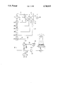
The invention is illustrated in greater detail in the example of execution depicted in the drawing showing a flow chart for a steam turbine plant constructed in accordance with the invention.
A boiler 1 is connected by means of a line 2 with a high-pressure stage 3 of a steam turbine 4. The turbine has a plurality of extraction points 5, 8, 9, 12, 13 and the exhaust point 14. Point 5 is connected with a middle pressure stage 7 by means of a line 6. Stage 7 has two extraction points 8, 9, the latter being connected with a low pressure stage 11 by means of a line 10. Stage 11 has extraction points 12, 13, and the exhaust point 14. Shaft 15 of the steam turbine 4 is connected to an electrical generator 16.
The exhaust point 14 is the exhaust end of the steam turbine 4, and is connected with a condenser 18 by means of a line 17 in which the exhaust steam is condensed in the known manner. The circulating medium flowing through condenser 18 is e.g. air cooled by means of a cooling tower 19.
The condensate from the condenser 18 goes through a line 20, a condensate pump 21, a heat exchanger 22, as well as through feed water heaters 23 through 27, and a feed water pump 28, and then back into the boiler 1.
From the condenser 18, a suction line 29 leads to the suction end of a steam jet compressor 30 to draw gases and steam from the condenser. The motive end of the compressor is fed through lines 31, 32, which connects with the extraction point 13, which is the extraction point having the lowest bleeder steam pressure except for the exhaust pressure at the exhaust point 14. A portion of bleeder steam from line 32 flows through line 39 to first feed water heater 23. The pressure at the extraction point 13, during the different operational conditions of the steam turbine unit, lies continuously or temporarily below atmospheric. The motive end of the steam jet compressor 30 is therefore fed with a partial flow of the bleeder steam from the extraction point 13.
The compression or exhaust end of the steam jet compressor 30 is connected with the heat exchanger 22 by means of a line 33. This heat exchanger lies ina line 34 downstream behind the condenser 18 between condensate pump 21 and the first feed water heater 23. A suction pump 36 is connected to the heat exchanger 22 by means of a suction line 35. This pump can be a water ring pump, a water jet pump, a steam jet pump, or a combination of these. The outlet 37 connects with the atmosphere.

Claims (3)

What is claimed is:
1. In a power generating steam turbine plant comprising
a multistage steam turbine having a feed end and an exhaust end
a boiler for feeding steam to said feed end
a condenser connecting to said exhaust end
a series of feed water heaters for preheating feed water for said boiler
a plurality of extraction points on said turbine to bleed steam therefrom to supply heat to said feed water heaters
an improved means for evacuating said condenser comprising
a steam jet compressor having a motive end, a suction end and a compression end
said motive end being connected to the extraction point having the lowest bleed pressure next to the exhaust pressure said suction end being connected to said condenser
a heat exchanger connected in series between said condenser and the first in said series of feed water heaters, said heat exchanger having an inlet and an outlet, said inlet being connected to said compression end of the compressor and said outlet being connected to the atmosphere through a suction pump.
2. The improved means for evacuating condensate of claim 1 in which steam pressure on said motive end of the compressor varies solely with the turbine load.
3. The improved means for evacuating the condenser of claim 1 in which said compressor is dimensioned so that the steam pressure at its exhaust end is equal to at least 25% and preferably greater than 50% of the steam pressure at said lowest bleed pressure extraction point which is next to the exhaust point.
US07/083,447 1986-08-20 1987-08-10 Steam turbine system Expired - Fee Related US4748815A (en)

Applications Claiming Priority (4)

Application Number Priority Date Filing Date Title
DE3628186 1986-08-20
DE3719861A DE3719861C2 (en) 1986-08-20 1987-06-13 STEAM TURBINE SYSTEM
DE3719861 1987-06-13

Publications (1)

Publication Number Publication Date
US4748815A true US4748815A (en) 1988-06-07

Family

ID=25846695

Family Applications (1)

Application Number Title Priority Date Filing Date
US07/083,447 Expired - Fee Related US4748815A (en) 1986-08-20 1987-08-10 Steam turbine system

Country Status (2)

Country Link
US (1) US4748815A (en)
DE (2) DE3719861C2 (en)

Cited By (10)

* Cited by examiner, † Cited by third party
Publication number Priority date Publication date Assignee Title
US5165237A (en) * 1991-03-08 1992-11-24 Graham Corporation Method and apparatus for maintaining a required temperature differential in vacuum deaerators
US6125634A (en) * 1992-09-30 2000-10-03 Siemens Aktiengesellschaft Power plant
US6145315A (en) * 1995-12-29 2000-11-14 Asea Brown Boveri Ag Process and equipment arrangement for the preheating and multistage deaeration of water
US20030000215A1 (en) * 2000-02-09 2003-01-02 Thomas Koenig Method and device for evacuating a turbine condenser
US20110005225A1 (en) * 2009-01-30 2011-01-13 Hitachi-Ge Nuclear Energy, Ltd. Electric Power Plant, and Method for Running Electric Power Plant
US20110283704A1 (en) * 2009-01-30 2011-11-24 Hitachi, Ltd. Power Plant
WO2016202653A1 (en) * 2015-06-18 2016-12-22 Epc Engineering Consulting Gmbh Efficient method for decontaminating waste gases and waste water containing cyanide in a method for producing alkali metal cyanides
CN110656986A (en) * 2019-10-15 2020-01-07 中国电建集团山东电力建设第一工程有限公司 Circulating cooling water system of steam turbine and operation method thereof
CN113006888A (en) * 2021-02-08 2021-06-22 浙江大学 Novel thermoelectric unit high-pressure steam extraction pressure difference utilization system and method
US11053131B2 (en) 2015-06-18 2021-07-06 Cyplus Gmbh Process for the preparation of sodium cyanide

Families Citing this family (2)

* Cited by examiner, † Cited by third party
Publication number Priority date Publication date Assignee Title
DE4313805A1 (en) * 1993-04-27 1994-11-03 Siemens Ag Sealing arrangement for at least one passage of a shaft through a housing
CN109990305B (en) * 2019-03-19 2023-09-15 华电电力科学研究院有限公司 White smoke plume eliminating device for coal-fired power plant and working method

Citations (2)

* Cited by examiner, † Cited by third party
Publication number Priority date Publication date Assignee Title
GB234581A (en) * 1924-03-27 1925-06-04 English Electric Co Ltd Improvements in steam turbine power plant
US2707239A (en) * 1948-12-20 1955-04-26 Frederick W Richl Apparatus for utilizing waste heat

Patent Citations (2)

* Cited by examiner, † Cited by third party
Publication number Priority date Publication date Assignee Title
GB234581A (en) * 1924-03-27 1925-06-04 English Electric Co Ltd Improvements in steam turbine power plant
US2707239A (en) * 1948-12-20 1955-04-26 Frederick W Richl Apparatus for utilizing waste heat

Cited By (23)

* Cited by examiner, † Cited by third party
Publication number Priority date Publication date Assignee Title
US5165237A (en) * 1991-03-08 1992-11-24 Graham Corporation Method and apparatus for maintaining a required temperature differential in vacuum deaerators
US5297389A (en) * 1991-03-08 1994-03-29 Graham Corporation Method and apparatus for maintaining a required temperature differential in vacuum deaerators
US5343705A (en) * 1991-03-08 1994-09-06 Graham Corporation Method and apparatus for maintaining a required temperature differential in vacuum deaerators
US6125634A (en) * 1992-09-30 2000-10-03 Siemens Aktiengesellschaft Power plant
US6145315A (en) * 1995-12-29 2000-11-14 Asea Brown Boveri Ag Process and equipment arrangement for the preheating and multistage deaeration of water
US20030000215A1 (en) * 2000-02-09 2003-01-02 Thomas Koenig Method and device for evacuating a turbine condenser
US6755023B2 (en) * 2000-02-09 2004-06-29 Siemens Aktiengesellschaft Method and device for evacuating a turbine condenser
US8695347B2 (en) * 2009-01-30 2014-04-15 Hitachi, Ltd. Power plant
US20110283704A1 (en) * 2009-01-30 2011-11-24 Hitachi, Ltd. Power Plant
US8448439B2 (en) * 2009-01-30 2013-05-28 Hitachi-Ge Nuclear Energy, Ltd. Electric power plant, and method for running electric power plant
US20110005225A1 (en) * 2009-01-30 2011-01-13 Hitachi-Ge Nuclear Energy, Ltd. Electric Power Plant, and Method for Running Electric Power Plant
EP3677550A1 (en) * 2015-06-18 2020-07-08 EPC Engineering & Technologies GmbH Method for producing alkali metal cyanides
CN107750235A (en) * 2015-06-18 2018-03-02 Epc工程与技术有限公司 Prepare the effective ways of the removing toxic substances of the waste gas and waste water containing cyanide in the method for alkali metal cyanide
WO2016202653A1 (en) * 2015-06-18 2016-12-22 Epc Engineering Consulting Gmbh Efficient method for decontaminating waste gases and waste water containing cyanide in a method for producing alkali metal cyanides
US10730758B2 (en) 2015-06-18 2020-08-04 EPC Engineering & Technologies GmbH Efficient method for decontaminating waste gases and waste water containing cyanide in a method for producing alkali metal cyanides
CN107750235B (en) * 2015-06-18 2021-03-19 Epc工程与技术有限公司 Effective method for detoxifying cyanide-containing waste gases and waste waters in a process for producing alkali metal cyanides
AU2016279761B2 (en) * 2015-06-18 2021-04-01 EPC Engineering & Technologies GmbH Efficient method for decontaminating waste gases and waste water containing cyanide in a method for producing alkali metal cyanides
RU2750782C2 (en) * 2015-06-18 2021-07-02 ЦиПлюс ГмбХ Efficient method of neutralizing cyanide-containing gaseous wastes and waste water in method of producing alkali metal cyanides
US11053131B2 (en) 2015-06-18 2021-07-06 Cyplus Gmbh Process for the preparation of sodium cyanide
US11905179B2 (en) 2015-06-18 2024-02-20 Cyplus Gmbh Efficient method for decontaminating waste gases and waste water containing cyanide in a method for producing alkali metal cyanides
CN110656986A (en) * 2019-10-15 2020-01-07 中国电建集团山东电力建设第一工程有限公司 Circulating cooling water system of steam turbine and operation method thereof
CN110656986B (en) * 2019-10-15 2024-01-19 中国电建集团山东电力建设第一工程有限公司 Circulating cooling water system of steam turbine and operation method thereof
CN113006888A (en) * 2021-02-08 2021-06-22 浙江大学 Novel thermoelectric unit high-pressure steam extraction pressure difference utilization system and method

Also Published As

Publication number Publication date
DE3719861A1 (en) 1988-02-25
DE8708383U1 (en) 1988-10-20
DE3719861C2 (en) 1988-08-04

Similar Documents

Publication Publication Date Title
US4748815A (en) Steam turbine system
US5896740A (en) Dual cycle turbine engine having increased efficiency and heat recovery system for use therein
US5622044A (en) Apparatus for augmenting power produced from gas turbines
US5799481A (en) Method of operating a gas-turbine group combined with a waste-heat steam generator and a steam consumer
US20060254280A1 (en) Combined cycle power plant using compressor air extraction
US3835650A (en) Steam air preheater for a steam boiler system
US6422019B1 (en) Apparatus for augmenting power produced from gas turbines
JP2005315244A (en) Device for using exhaust heat of compressor
EP0940563B1 (en) Gas turbine combined cycle
GB2280224A (en) Method of and apparatus for augmenting power produced from gas turbines
US4366675A (en) Geothermal turbine installation
US5137681A (en) Method and apparatus for recycling turbine exhaust steam in electrical power generation
US20040003593A1 (en) Steam turbine plant, and method of operating a steam turbine plant
US4387576A (en) Two-phase thermal energy conversion system
US6012290A (en) Condenser performance optimizer in steam power plants
GB2099568A (en) Plant for utilization of low-potential waste heat of a gas-pipeline compressor station
US5140818A (en) Internal moisture separation cycle
CN109555666A (en) The system and method for recycling the condensed water generated in air compressor chillers
US20040011047A1 (en) Gas turbine and air turbine installation and method of operating a power station installation, in particular a gas turbine and air turbine installation
US4249385A (en) Two-phase thermal energy conversion system
US3705494A (en) Holding system for steam power cycle
US6755023B2 (en) Method and device for evacuating a turbine condenser
US5794447A (en) Rankine cycle boiler feed via hydrokinetic amplifier
EP2516810B1 (en) Arrangement in a gas turbine process
RU2740670C1 (en) Method of operation of steam-gas plant of power plant

Legal Events

Date Code Title Description
AS Assignment

Owner name: KORTING HANNOVER, AKTIENGESELLSCHAFT BANDENSTEDTER

Free format text: ASSIGNMENT OF ASSIGNORS INTEREST.;ASSIGNORS:JUNIOR, ALFRED;AUMANN, WALTER;REEL/FRAME:004836/0986

Effective date: 19870625

Owner name: KORTING HANNOVER,GERMANY

Free format text: ASSIGNMENT OF ASSIGNORS INTEREST;ASSIGNORS:JUNIOR, ALFRED;AUMANN, WALTER;REEL/FRAME:004836/0986

Effective date: 19870625

FPAY Fee payment

Year of fee payment: 4

REMI Maintenance fee reminder mailed
LAPS Lapse for failure to pay maintenance fees
FP Lapsed due to failure to pay maintenance fee

Effective date: 19960612

STCH Information on status: patent discontinuation

Free format text: PATENT EXPIRED DUE TO NONPAYMENT OF MAINTENANCE FEES UNDER 37 CFR 1.362