US4735459A - Wheel system adapted to be rapidly dismantled from a support - Google Patents
Wheel system adapted to be rapidly dismantled from a support Download PDFInfo
- Publication number
- US4735459A US4735459A US06/877,356 US87735686A US4735459A US 4735459 A US4735459 A US 4735459A US 87735686 A US87735686 A US 87735686A US 4735459 A US4735459 A US 4735459A
- Authority
- US
- United States
- Prior art keywords
- wheel
- leg member
- notch
- web
- article
- Prior art date
- Legal status (The legal status is an assumption and is not a legal conclusion. Google has not performed a legal analysis and makes no representation as to the accuracy of the status listed.)
- Expired - Fee Related
Links
Images


Classifications
-
- B—PERFORMING OPERATIONS; TRANSPORTING
- B60—VEHICLES IN GENERAL
- B60B—VEHICLE WHEELS; CASTORS; AXLES FOR WHEELS OR CASTORS; INCREASING WHEEL ADHESION
- B60B33/00—Castors in general; Anti-clogging castors
- B60B33/0002—Castors in general; Anti-clogging castors assembling to the object, e.g. furniture
- B60B33/0005—Castors in general; Anti-clogging castors assembling to the object, e.g. furniture characterised by mounting method
- B60B33/001—Castors in general; Anti-clogging castors assembling to the object, e.g. furniture characterised by mounting method by snapping, clicking or latching in
-
- B—PERFORMING OPERATIONS; TRANSPORTING
- B60—VEHICLES IN GENERAL
- B60B—VEHICLE WHEELS; CASTORS; AXLES FOR WHEELS OR CASTORS; INCREASING WHEEL ADHESION
- B60B19/00—Wheels not otherwise provided for or having characteristics specified in one of the subgroups of this group
-
- B—PERFORMING OPERATIONS; TRANSPORTING
- B60—VEHICLES IN GENERAL
- B60B—VEHICLE WHEELS; CASTORS; AXLES FOR WHEELS OR CASTORS; INCREASING WHEEL ADHESION
- B60B33/00—Castors in general; Anti-clogging castors
- B60B33/0036—Castors in general; Anti-clogging castors characterised by type of wheels
- B60B33/0039—Single wheels
-
- B—PERFORMING OPERATIONS; TRANSPORTING
- B60—VEHICLES IN GENERAL
- B60B—VEHICLE WHEELS; CASTORS; AXLES FOR WHEELS OR CASTORS; INCREASING WHEEL ADHESION
- B60B33/00—Castors in general; Anti-clogging castors
- B60B33/0047—Castors in general; Anti-clogging castors characterised by details of the rolling axle
- B60B33/0049—Castors in general; Anti-clogging castors characterised by details of the rolling axle the rolling axle being horizontal
-
- B—PERFORMING OPERATIONS; TRANSPORTING
- B60—VEHICLES IN GENERAL
- B60B—VEHICLE WHEELS; CASTORS; AXLES FOR WHEELS OR CASTORS; INCREASING WHEEL ADHESION
- B60B33/00—Castors in general; Anti-clogging castors
- B60B33/006—Castors in general; Anti-clogging castors characterised by details of the swivel mechanism
- B60B33/0063—Castors in general; Anti-clogging castors characterised by details of the swivel mechanism no swivelling action, i.e. no real caster
-
- B—PERFORMING OPERATIONS; TRANSPORTING
- B60—VEHICLES IN GENERAL
- B60B—VEHICLE WHEELS; CASTORS; AXLES FOR WHEELS OR CASTORS; INCREASING WHEEL ADHESION
- B60B2200/00—Type of product being used or applied
- B60B2200/20—Furniture or medical appliances
-
- B—PERFORMING OPERATIONS; TRANSPORTING
- B60—VEHICLES IN GENERAL
- B60B—VEHICLE WHEELS; CASTORS; AXLES FOR WHEELS OR CASTORS; INCREASING WHEEL ADHESION
- B60B2200/00—Type of product being used or applied
- B60B2200/20—Furniture or medical appliances
- B60B2200/22—Chairs
Definitions
- the present invention relates to a wheel system adapted to be dismantled very rapidly from a support such as the legs of a reclining chair or the like.
- the wheel system according to the invention is unique in that the wheels include vertically oriented annular webs which are receivable in vertical notches open towards the ground and which notches are made in an outwardly offset manner at the base of a leg or other support.
- the rounded bottom of the legs defines a stop against which part of the inner edge of the wheels bear, either when at rest or when the wheels rotate when the chair or other article of furniture is being moved.
- FIG. 1 is an exploded view in perspective of a wheel system adapted to be dismantled from the legs of a chair in accordance with the invention.
- FIG. 2 is a side view having sections broken away showing the manner in which a wheel is placed in position with respect to a leg of a chair or other article of furniture.
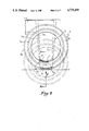
- FIGS. 3 and 4 illustrate on an enlarged scale and in partial transverse section along lines III--III of FIG. 2, the two respective positions for a wheel with respect to a chair or other article of furniture.
- FIG. 1 partially illustrates the frame 1 of a chair provided with legs 2 with which it is desired to associte a wheel 3 in an easily dismountable manner.
- the frame 1 may constitute the principal element of a reclining chair or other article which is desired to be moved or manipulated like a wheelbarrow.
- Each leg 2 comprises a small vertical panel 2a of trapezoidal form whose base constitutes the free end of the leg of a chair, chaise or other article of furniture.
- Two upwardly divergent oblique sides extend outwardly of the panel 2a and are identified as flanges 2b, 2c, which are oriented perpendicularly to the panel. In this way, leg 2 is recessed and outwardly open.
- the dimensions of the legs are such that the frames 1 may be stacked one on the other with their respective legs engaging in those of other frames.
- flange 2g which is oriented downwardly and parallel to wall 2d.
- flange 2g, partition 2f and wall 2d define a vertical notch 4 which is open downwardly with the upper portions thereof 4a being convex towards the ground.
- Each wheel 3 includes an annular web 3a of which the periphery is associated with a rim 3b oriented perpendicularly thereto. Therefore, each wheel is in the form of a circular element whose sides include the web 3a and the rim 3b.
- the inner face of web 3a is provided with an annular groove 3c for purposes which will be better explained hereinbelow. It is noted that the inner periphery of web 3a defines an opening having a radius greater than that of the upper portion 4a of the notch 4, while the thickness is such as to enable the web 3a to be received within the notch 4.
- notch 4 is offset outwardly with respect to leg 2, with the result that the outer face of web 3a (not shown in FIG. 1) may be positioned against the edges of flanges 2b and 2c when flanges 2g is oriented in the central opening of the web so as to engage the web 3a between the flange 2g and the wall 2d of the leg 2, as illustrated in discontinuous lines in FIG. 2.
- the wheels are withdrawn by exerting a force in the direction opposite that of arrow F after the frame is raised so as to allow the removal of webs 3a from the notches 4.
- the height of the webs 3a of the wheels 3 is such that the rims 3b which are associated therewith project beyond or at the least are flush with the bottom of the legs 2 which are closed on their sides by tabs 2i.
Landscapes
- Engineering & Computer Science (AREA)
- Mechanical Engineering (AREA)
- Handcart (AREA)
- Body Structure For Vehicles (AREA)
- Automatic Assembly (AREA)
- Automobile Manufacture Line, Endless Track Vehicle, Trailer (AREA)
- Legs For Furniture In General (AREA)
- Processing Of Solid Wastes (AREA)
- Vehicle Body Suspensions (AREA)
- Yarns And Mechanical Finishing Of Yarns Or Ropes (AREA)
- Regulating Braking Force (AREA)
- Replacement Of Web Rolls (AREA)
- Automatic Cycles, And Cycles In General (AREA)
- Forklifts And Lifting Vehicles (AREA)
Abstract
A wheel support system for articles of furniture and the like wherein the wheels are adapted to be readily dismantled from their support to thereby permit stacking of the furniture and wherein the wheels are engageable in vertical notches which are offset at the base of the legs of the furniture in such a manner that the wheels engage the lowermost portion of the legs and are rotatable with respect thereto.
Description
1. Field of the Invention
The present invention relates to a wheel system adapted to be dismantled very rapidly from a support such as the legs of a reclining chair or the like.
2. History of the Related Art
It is known that individuals appreciate reclining chairs for sunbathing which may be moved like a wheelbarrow or rolled on two wheels associated with the front or rear feet or legs of the chair or other article. However, when chairs are provided with wheels, it is virtually impossible to stack them unless the wheels are dismantled. It will be readily understood that such dismantling is tedious, with the result that it is not possible to accomplish the desired result.
It is an object of the improvements forming the subject matter of the present invention to produce a wheel system for lounge and other chairs which permits the wheels to be dismantled instantaneously and without using any tool.
The wheel system according to the invention is unique in that the wheels include vertically oriented annular webs which are receivable in vertical notches open towards the ground and which notches are made in an outwardly offset manner at the base of a leg or other support. The rounded bottom of the legs defines a stop against which part of the inner edge of the wheels bear, either when at rest or when the wheels rotate when the chair or other article of furniture is being moved.
Thus, when the wheels of the present invention are engaged in the vertical notches, their peripheral surface will rest against the ground, with the result that, by equipping the two corresponding legs of a reclining chair or the like for sunbathing, such chair may be moved like a wheelbarrow. When it is desired to stack such articles or chairs, it suffices to withdraw the wheels from their vertical notches and to engage the corresponding legs within one another.
The invention will be more readily understood on reading the following description with reference to the accompanying drawings, in which:
FIG. 1 is an exploded view in perspective of a wheel system adapted to be dismantled from the legs of a chair in accordance with the invention.
FIG. 2 is a side view having sections broken away showing the manner in which a wheel is placed in position with respect to a leg of a chair or other article of furniture.
FIGS. 3 and 4 illustrate on an enlarged scale and in partial transverse section along lines III--III of FIG. 2, the two respective positions for a wheel with respect to a chair or other article of furniture.
FIG. 1 partially illustrates the frame 1 of a chair provided with legs 2 with which it is desired to associte a wheel 3 in an easily dismountable manner. The frame 1 may constitute the principal element of a reclining chair or other article which is desired to be moved or manipulated like a wheelbarrow.
Each leg 2 comprises a small vertical panel 2a of trapezoidal form whose base constitutes the free end of the leg of a chair, chaise or other article of furniture. Two upwardly divergent oblique sides extend outwardly of the panel 2a and are identified as flanges 2b, 2c, which are oriented perpendicularly to the panel. In this way, leg 2 is recessed and outwardly open. The dimensions of the legs are such that the frames 1 may be stacked one on the other with their respective legs engaging in those of other frames.
The lower parts of the two flanges 2b, 2c are joined by a vertical wall 2d of which the free edge is upwardly concave. The edge extends inwardly from a vertical flange 2g which is oriented downwardly and parallel to wall 2d. In this way, flange 2g, partition 2f and wall 2d define a vertical notch 4 which is open downwardly with the upper portions thereof 4a being convex towards the ground.
Each wheel 3 includes an annular web 3a of which the periphery is associated with a rim 3b oriented perpendicularly thereto. Therefore, each wheel is in the form of a circular element whose sides include the web 3a and the rim 3b. The inner face of web 3a is provided with an annular groove 3c for purposes which will be better explained hereinbelow. It is noted that the inner periphery of web 3a defines an opening having a radius greater than that of the upper portion 4a of the notch 4, while the thickness is such as to enable the web 3a to be received within the notch 4.
From the foregoing description, it is observed that notch 4 is offset outwardly with respect to leg 2, with the result that the outer face of web 3a (not shown in FIG. 1) may be positioned against the edges of flanges 2b and 2c when flanges 2g is oriented in the central opening of the web so as to engage the web 3a between the flange 2g and the wall 2d of the leg 2, as illustrated in discontinuous lines in FIG. 2.
In order to secure a wheel in position, it suffices to subject it to an upward translation in the direction of arrow F (FIGS. 2 and 3) so that the web 3a penetrates into notch 4. In this position, the inner edge of the web comes into contact with the upper portion 4a of the notch 4. The inner face of flange 2g includes a lug 2h which projects into notch 4 so that, when wheel 3 is placed in position in this notch, the lug will be resiliently engaged in groove 3c of wheel 3 due to the elasticity of the flange 2g which is flexed outwardly upon the passage of web 3a. Each wheel is therefore maintained in mounted position within a notch so that the frame 1 may be raised without the wheels being displaced from the legs 2.
The wheels are withdrawn by exerting a force in the direction opposite that of arrow F after the frame is raised so as to allow the removal of webs 3a from the notches 4. The height of the webs 3a of the wheels 3 is such that the rims 3b which are associated therewith project beyond or at the least are flush with the bottom of the legs 2 which are closed on their sides by tabs 2i.
It must, moreover, be understood that the foregoing description has been given only by way of example and that it in no way limits the domain of the invention which would not be exceeded by replacing the details of execution described by any other equivalents.
Claims (8)
1. A removable wheel support assembly for article supports wherein the article support includes a frame portion and at least one depending leg member comprising said leg member having a base portion and outer vertically oriented wall portions, a partition extending outwardly from said vertically oriented wall portions, a depending flange connected to said partition and spaced outwardly and in generally parallel relationship to said vertically oriented wall portions so as to create a notch therebetween, a wheel selectively mountable within said notch, said wheel having an outer peripheral surface and an inner annular and vertically oriented web which defines an opening through said wheel, said annular web being of a width to be cooperatively and removably received within said notch so that said wheel is oriented so as to rotate within said notch and around an axis of rotation which extends generally perpendicularly between said depending flange and said leg member, and said wheel being of a diameter so that the peripheral surface thereof extends downwardly so as to be aligned with or extends beyond said base portion of said leg member when said wheel is mounted within said notch.
2. The wheel support assembly of claim 1 in which said annular web of said wheel includes a generally circular inner edge which is defined having a first radius of curvature, said partition means having a lowermost convex edge being defined by a second radius of curvature, said second radius of curvature being less than said first radius of curvature.
3. The wheel support assembly of claim 1 in which said peripheral portion of said wheel extends generally perpendicularly with respect to said web.
4. The wheel support assembly of claim 1 including an annular groove formed in said annular web, and means protruding within said notch for selectively engaging said groove in said annular web so as to frictionally retain said wheel within said notch.
5. The wheel support assembly of claim 4 in which said depending flange portion is resiliently movable with respect to said vertically oriented wall portions of said leg member.
6. The wheel support assembly of claim 1 in which said vertically oriented wall portions of said leg member include a pair of vertically extending and opposing flange members which are mounted perpendicularly and outwardly with respect to the frame portion and which are divergent from one another upwardly from said base portion of the leg member, said opposing flange members defining an opening therebetween which is of a size to selectively receive the leg member of another article support so that the article supports may be stacked in vertical relationship with respect to one another.
7. In an article of furniture having a frame and at least one depending leg member the improvement comprising, said leg member having a base portion and a pair of vertically oriented and outwardly diverging flange members which extend upwardly of said base portion, an elongated opening defined between said flange members of a size to permit the leg member of another article of furniture to be cooperatively received therein so that such articles of furniture may be stacked vertically with respect to one another, a wheel, said wheel being defined by an outer peripheral surface and having an inner annular web defining an opening through said wheel, a flange member mounted to said leg member and extending outwardly and downwardly in parallel relationship adjacent to said leg member so as to create a notch therebetween, said web portion of said wheel being selectively receivable within said notch so that said leg member is rotatably supported on said wheel.
8. The improvement in an article of furniture of claim 7 including means for securing said wheel within said notch.
Applications Claiming Priority (2)
| Application Number | Priority Date | Filing Date | Title |
|---|---|---|---|
| FR8510118 | 1985-06-28 | ||
| FR8510118A FR2583964B1 (en) | 1985-06-28 | 1985-06-28 | WHEEL SYSTEM QUICKLY REMOVABLE FROM A SUPPORT |
Publications (1)
| Publication Number | Publication Date |
|---|---|
| US4735459A true US4735459A (en) | 1988-04-05 |
Family
ID=9320902
Family Applications (1)
| Application Number | Title | Priority Date | Filing Date |
|---|---|---|---|
| US06/877,356 Expired - Fee Related US4735459A (en) | 1985-06-28 | 1986-06-23 | Wheel system adapted to be rapidly dismantled from a support |
Country Status (9)
| Country | Link |
|---|---|
| US (1) | US4735459A (en) |
| EP (1) | EP0208633B1 (en) |
| JP (1) | JPS624603A (en) |
| AT (1) | ATE38964T1 (en) |
| AU (1) | AU588605B2 (en) |
| DE (1) | DE3661302D1 (en) |
| ES (1) | ES294911Y (en) |
| FR (1) | FR2583964B1 (en) |
| ZA (1) | ZA864721B (en) |
Cited By (11)
| Publication number | Priority date | Publication date | Assignee | Title |
|---|---|---|---|---|
| US5071196A (en) * | 1988-07-11 | 1991-12-10 | Sm Sbarro Mottas Engineering S.A. | Wheel for a motor vehicle or towed vehicle and a vehicle fitted with such a wheel |
| US5136751A (en) * | 1991-04-30 | 1992-08-11 | Master Manufacturing Co. | Wheel assembly |
| US5419619A (en) * | 1993-12-17 | 1995-05-30 | Wear And Tear, Inc. | Hubless wheel |
| US5490719A (en) * | 1993-12-17 | 1996-02-13 | Wear And Tear, Inc. | Racing wheel |
| US5669619A (en) * | 1995-08-22 | 1997-09-23 | Kim; Il Yoo | Portable wheelchair |
| US6550100B2 (en) | 2001-02-08 | 2003-04-22 | Waxman Industries, Inc. | Caster assembly with multi-position support pieces |
| US6728991B2 (en) | 2002-04-15 | 2004-05-04 | Waxman Industries, Inc. | Caster assembly with sliding side support piece |
| US20080276417A1 (en) * | 2007-05-07 | 2008-11-13 | Frame William F | Caster with weight transferring tab |
| USD602769S1 (en) | 2008-05-05 | 2009-10-27 | Jacob Holtz Company | Caster |
| US8075010B2 (en) * | 2010-05-14 | 2011-12-13 | Specialized Bicycle Components, Inc. | Rear axle system for bicycle |
| US9027204B2 (en) | 2007-05-07 | 2015-05-12 | Jacob Holtz Company | Casters having weight transferring tab |
Citations (4)
| Publication number | Priority date | Publication date | Assignee | Title |
|---|---|---|---|---|
| US3869105A (en) * | 1972-01-07 | 1975-03-04 | Guy Raymond Eng Co Ltd | Furniture legs |
| US3977040A (en) * | 1975-02-27 | 1976-08-31 | Sugatsune Industrial Co., Ltd. | Castor |
| US4340198A (en) * | 1979-05-11 | 1982-07-20 | Mechanische Weberei Gmbh | Stand for a projection screen |
| DE3602475A1 (en) * | 1985-02-07 | 1986-08-07 | Bruandet S.A., Orchamps | REEL ARRANGEMENT |
Family Cites Families (8)
| Publication number | Priority date | Publication date | Assignee | Title |
|---|---|---|---|---|
| CA331106A (en) * | 1933-03-21 | The Dominion Oxygen Company | Welding rod | |
| BE387437A (en) * | ||||
| US1406122A (en) * | 1920-04-27 | 1922-02-07 | Welch | Vehicle wheel |
| US1566467A (en) * | 1924-11-10 | 1925-12-22 | Sergio Faustino De Cast Iznaga | Wheel without spokes |
| FR980314A (en) * | 1943-01-25 | 1951-05-10 | Improvements made to rolling devices in contact with a load-bearing surface, in particular wheels for vehicles | |
| GB769842A (en) * | 1954-09-30 | 1957-03-13 | Nojima Takeo | Improvements in and relating to wheel arrangements for transportation devices |
| US3329444A (en) * | 1966-11-22 | 1967-07-04 | Lidov Arthur | Vehicle frame and spokeless wheel arrangement |
| US4045096A (en) * | 1976-03-29 | 1977-08-30 | The Spokeless Wheel Patent Proceeds Partnership | Spokeless wheel and shroud therefor |
-
1985
- 1985-06-28 FR FR8510118A patent/FR2583964B1/en not_active Expired
-
1986
- 1986-06-19 ES ES1986294911U patent/ES294911Y/en not_active Expired
- 1986-06-23 US US06/877,356 patent/US4735459A/en not_active Expired - Fee Related
- 1986-06-24 ZA ZA864721A patent/ZA864721B/en unknown
- 1986-06-26 AT AT86420171T patent/ATE38964T1/en not_active IP Right Cessation
- 1986-06-26 JP JP61151301A patent/JPS624603A/en active Pending
- 1986-06-26 AU AU59300/86A patent/AU588605B2/en not_active Ceased
- 1986-06-26 EP EP86420171A patent/EP0208633B1/en not_active Expired
- 1986-06-26 DE DE8686420171T patent/DE3661302D1/en not_active Expired
Patent Citations (4)
| Publication number | Priority date | Publication date | Assignee | Title |
|---|---|---|---|---|
| US3869105A (en) * | 1972-01-07 | 1975-03-04 | Guy Raymond Eng Co Ltd | Furniture legs |
| US3977040A (en) * | 1975-02-27 | 1976-08-31 | Sugatsune Industrial Co., Ltd. | Castor |
| US4340198A (en) * | 1979-05-11 | 1982-07-20 | Mechanische Weberei Gmbh | Stand for a projection screen |
| DE3602475A1 (en) * | 1985-02-07 | 1986-08-07 | Bruandet S.A., Orchamps | REEL ARRANGEMENT |
Cited By (15)
| Publication number | Priority date | Publication date | Assignee | Title |
|---|---|---|---|---|
| US5071196A (en) * | 1988-07-11 | 1991-12-10 | Sm Sbarro Mottas Engineering S.A. | Wheel for a motor vehicle or towed vehicle and a vehicle fitted with such a wheel |
| US5136751A (en) * | 1991-04-30 | 1992-08-11 | Master Manufacturing Co. | Wheel assembly |
| US5419619A (en) * | 1993-12-17 | 1995-05-30 | Wear And Tear, Inc. | Hubless wheel |
| US5490719A (en) * | 1993-12-17 | 1996-02-13 | Wear And Tear, Inc. | Racing wheel |
| US5669619A (en) * | 1995-08-22 | 1997-09-23 | Kim; Il Yoo | Portable wheelchair |
| US6550100B2 (en) | 2001-02-08 | 2003-04-22 | Waxman Industries, Inc. | Caster assembly with multi-position support pieces |
| US6728991B2 (en) | 2002-04-15 | 2004-05-04 | Waxman Industries, Inc. | Caster assembly with sliding side support piece |
| US20080276417A1 (en) * | 2007-05-07 | 2008-11-13 | Frame William F | Caster with weight transferring tab |
| US7546662B2 (en) | 2007-05-07 | 2009-06-16 | Jacob Holtz Company | Caster with weight transferring tab |
| US20090211054A1 (en) * | 2007-05-07 | 2009-08-27 | Frame William F | Caster with weight transferring tab |
| US8042226B2 (en) | 2007-05-07 | 2011-10-25 | Jacob Holtz Company | Caster with weight transferring tab |
| US8407856B2 (en) | 2007-05-07 | 2013-04-02 | Jacob Holtz Company | Caster with weight transferring tab |
| US9027204B2 (en) | 2007-05-07 | 2015-05-12 | Jacob Holtz Company | Casters having weight transferring tab |
| USD602769S1 (en) | 2008-05-05 | 2009-10-27 | Jacob Holtz Company | Caster |
| US8075010B2 (en) * | 2010-05-14 | 2011-12-13 | Specialized Bicycle Components, Inc. | Rear axle system for bicycle |
Also Published As
| Publication number | Publication date |
|---|---|
| ATE38964T1 (en) | 1988-12-15 |
| DE3661302D1 (en) | 1989-01-05 |
| ES294911U (en) | 1986-12-16 |
| FR2583964B1 (en) | 1987-09-11 |
| JPS624603A (en) | 1987-01-10 |
| AU5930086A (en) | 1987-01-08 |
| AU588605B2 (en) | 1989-09-21 |
| EP0208633A1 (en) | 1987-01-14 |
| EP0208633B1 (en) | 1988-11-30 |
| ES294911Y (en) | 1987-08-01 |
| ZA864721B (en) | 1987-02-25 |
| FR2583964A1 (en) | 1987-01-02 |
Similar Documents
| Publication | Publication Date | Title |
|---|---|---|
| US4735459A (en) | Wheel system adapted to be rapidly dismantled from a support | |
| US5463966A (en) | Framework for shelving unit | |
| US6113042A (en) | Self-adjusting support system | |
| CA1327183C (en) | Shelf support system having a triangular support post | |
| US4045104A (en) | Cabinet structure and method of construction | |
| AU713464B2 (en) | Support system with quick-adjust support assembly | |
| US4644876A (en) | Knockdown table or the like | |
| US3187693A (en) | Article of furniture | |
| US4821986A (en) | Multiple leg furniture base | |
| US2837219A (en) | Shelving device | |
| WO2004052148A1 (en) | Adjustable furniture support apparatus | |
| US4729136A (en) | Universal sleep system support | |
| US4874209A (en) | Rolling drawer | |
| US3207462A (en) | Pedestal assembly | |
| US4424604A (en) | Wheel kit for an item of furniture | |
| US4895339A (en) | Detachable swivelling structure | |
| US5439237A (en) | Snowmobile ski wheels | |
| US5865129A (en) | Knock-down table | |
| US3276403A (en) | Knockdown steel shelving unit and corner fastening means therefor | |
| US3262734A (en) | Table and seat combination | |
| US3994466A (en) | Shroud for pedestal chair | |
| US5772055A (en) | Rotatable display tower | |
| US2915351A (en) | Desk construction | |
| US3009739A (en) | Stool | |
| US2364516A (en) | Stool |
Legal Events
| Date | Code | Title | Description |
|---|---|---|---|
| AS | Assignment |
Owner name: SOCIETE POUR LA TRANSFORMATION DES MATIERES PLASTI Free format text: ASSIGNMENT OF ASSIGNORS INTEREST.;ASSIGNOR:MASSONNET, HENRY;REEL/FRAME:005002/0428 Effective date: 19890105 |
|
| REMI | Maintenance fee reminder mailed | ||
| LAPS | Lapse for failure to pay maintenance fees | ||
| FP | Lapsed due to failure to pay maintenance fee |
Effective date: 19920405 |
|
| STCH | Information on status: patent discontinuation |
Free format text: PATENT EXPIRED DUE TO NONPAYMENT OF MAINTENANCE FEES UNDER 37 CFR 1.362 |