US4735252A - System for reforming levitated molten metal into metallic forms - Google Patents
System for reforming levitated molten metal into metallic forms Download PDFInfo
- Publication number
- US4735252A US4735252A US06/819,376 US81937686A US4735252A US 4735252 A US4735252 A US 4735252A US 81937686 A US81937686 A US 81937686A US 4735252 A US4735252 A US 4735252A
- Authority
- US
- United States
- Prior art keywords
- conduit
- levitation
- metal
- molten
- molten metal
- Prior art date
- Legal status (The legal status is an assumption and is not a legal conclusion. Google has not performed a legal analysis and makes no representation as to the accuracy of the status listed.)
- Expired - Fee Related
Links
Images


Classifications
-
- B—PERFORMING OPERATIONS; TRANSPORTING
- B22—CASTING; POWDER METALLURGY
- B22D—CASTING OF METALS; CASTING OF OTHER SUBSTANCES BY THE SAME PROCESSES OR DEVICES
- B22D11/00—Continuous casting of metals, i.e. casting in indefinite lengths
- B22D11/14—Plants for continuous casting
- B22D11/145—Plants for continuous casting for upward casting
-
- B—PERFORMING OPERATIONS; TRANSPORTING
- B22—CASTING; POWDER METALLURGY
- B22D—CASTING OF METALS; CASTING OF OTHER SUBSTANCES BY THE SAME PROCESSES OR DEVICES
- B22D11/00—Continuous casting of metals, i.e. casting in indefinite lengths
- B22D11/06—Continuous casting of metals, i.e. casting in indefinite lengths into moulds with travelling walls, e.g. with rolls, plates, belts, caterpillars
- B22D11/0611—Continuous casting of metals, i.e. casting in indefinite lengths into moulds with travelling walls, e.g. with rolls, plates, belts, caterpillars formed by a single casting wheel, e.g. for casting amorphous metal strips or wires
- B22D11/0614—Continuous casting of metals, i.e. casting in indefinite lengths into moulds with travelling walls, e.g. with rolls, plates, belts, caterpillars formed by a single casting wheel, e.g. for casting amorphous metal strips or wires the casting wheel being immersed in a molten metal bath, and drawing out upwardly the casting strip
-
- B—PERFORMING OPERATIONS; TRANSPORTING
- B22—CASTING; POWDER METALLURGY
- B22D—CASTING OF METALS; CASTING OF OTHER SUBSTANCES BY THE SAME PROCESSES OR DEVICES
- B22D11/00—Continuous casting of metals, i.e. casting in indefinite lengths
- B22D11/06—Continuous casting of metals, i.e. casting in indefinite lengths into moulds with travelling walls, e.g. with rolls, plates, belts, caterpillars
- B22D11/0631—Continuous casting of metals, i.e. casting in indefinite lengths into moulds with travelling walls, e.g. with rolls, plates, belts, caterpillars formed by a travelling straight surface, e.g. through-like moulds, a belt
-
- B—PERFORMING OPERATIONS; TRANSPORTING
- B22—CASTING; POWDER METALLURGY
- B22D—CASTING OF METALS; CASTING OF OTHER SUBSTANCES BY THE SAME PROCESSES OR DEVICES
- B22D27/00—Treating the metal in the mould while it is molten or ductile ; Pressure or vacuum casting
- B22D27/02—Use of electric or magnetic effects
Definitions
- This invention relates to a method and apparatus which produces desired solid metal forms that are low in impurities and more particularly to such a method and apparatus which re-forms and solidifies levitated molten metal into metallic forms.
- Metals low in impurities are desirable for applications where product uniformity, metallurgical homogeneity and high fatigue resistance are required, such as in aerospace applications.
- Metallic components are often formed and shaped from metallic powders; for example, composite materials can be manufactured by sintering a mixture of metallic powders.
- the Dynapour made by Ajax Magnathermic consists of a trough including induction coils which are used to draw liquid metal against gravity over the lip of a crucible and direct the liquid metal into a mold or diecasting machine.
- the liquid metal may come into physical contact with the trough during transport. The contact can cause problems since some metals are more compatible with lining materials than others.
- liquid copper is compatible with graphite. Titanium, molybdenum, and other metals which form carbides with graphite actively corrode the graphite and therefore are much more difficult to maintain in pure form.
- Lowry et al. U.S. Pat. No. 4,414,285, disclose a continuous, contactless metal casting system which raises at a controlled rate molten metal introduced in a liquid state at the lower end of a casting column. A gap is maintained between the molten metal and the inner surface of the column but the gap is minimized to enhance heat transfer between the molten metal and a cooling jacket surrounding the casting column. Significantly, a solid in the form of a continuous rod is removed from the levitation column as the final product. The shape of the form is determined to some extent by the shape of the magnetic field.
- Amorphous, ribbon-shaped metals are presently formed by quenching a thin stream of liquid metal against a hollow metal drum chilled by water.
- the cooling rate required for sufficiently rapid solidification may be as high as 10 8 °C./sec.
- Contact of the liquid metal with the cooling drum rarely introduces impurities since the solidification is so rapid.
- conventional delivery of the liquid metal to the drum may introduce undesirable impurities to the metal.
- a still further object of this invention is to provide such a system which can produce high-quality filaments.
- Yet another object of this invention is to provide such a system which handles highly corrosive liquid alloys while minimizing introduction of impurities to the alloys.
- This invention results from the realization that extremely pure metallic forms can be achieved by conveying metal upwardly in a levitation conduit, maintaining the metal out of pressured contact with the sides of the conduit, and re-forming the molten metal output of the conduit into the solid metallic forms.
- solid metal is introduced into the levitation conduit and the re-forming is accomplished by gas atomization or rapid solidification, the metal once molten remains entirely free of impurities.
- This invention features an apparatus for manufacturing solidified metallic forms from levitated molten metal.
- a levitation conduit having an interior surface for accommodating the metal to be levitated and means for introducing the metal to the levitation conduit.
- induction coil means for inducing a moving magnetic field in the levitation conduit to levitate the metal and move it upwardly through the conduit and to maintain the outer surface of the levitated metal while molten out of pressured contact with the interior surface of the levitation conduit.
- the apparatus further includes a chamber for receiving molten metal output of the levitation conduit and means, disposed in the chamber, for re-forming the molten metal output and solidifying it.
- the means for re-forming includes means for atomizing the molten metal output into a powder.
- the means for atomizing may include means for directing a stream of gas onto the molten metal output or rotatable means for dispersing the molten metal output.
- the rotatable means can be a rotatable vessel having a concave face which rotatably contacts the molten metal output.
- the means for re-forming includes means for rapidly cooling by thermal conduction the molten metal output to solidify it into a thin form.
- the means for rapidly cooling includes a rotatable cooled drum which may have a smooth, continuous contact face which solidifies the molten metal output into a ribbon. The same or similar results may be obtained by impinging molten metal against a cooled continuous belt.
- the drum has a plurality of grooves disposed circumferentially about its contact face which solidify the molten metal output into a plurality of filaments.
- the means for rapidly cooling may cool the metal at least at the rate of 10 6 °C./sec..
- the moving magnetic field of induction coil means maintains the levitated metal in the molten state in a first cross-sectional dimension and the thin form fabricated by the means for rapidly cooling has a second cross-sectional dimension.
- the chamber is hermetically sealed, has been substantially evacuated of air and backfilled to contain an inert gas.
- the moving magnetic field of the induction coil means continuously maintains the outer surface of the levitated metal while molten out of contact with the interior surface of the levitation conduit.
- the interior surface of the levitation conduit may completely surround a cross-sectional dimension of the levitated metal and the means for introducing may include means for providing solid metal to the input end of the levitation conduit.
- the apparatus may further include means for adjusting the rate of introduction to the metal; the means for adjusting may include means for sensing the exit temperature of the molten metal output.
- the levitation conduit may be disposed in an inclined position and the apparatus may further include means for altering the inclined position of the levitation conduit.
- the means for re-forming includes means for directing the diverging gas stream onto the molten metal output.
- This invention also features an apparatus for manufacturing solidified metallic forms including a levitation conduit, means for providing solid metal to the input end of the levitation conduit, and induction coil means for inducing a moving magnetic field in the levitation conduit to levitate the metal and move it upwardly through the conduit, and to maintain the outer surface of the levitated metal while molten out of contact with the interior surface of the levitation conduit.
- This apparatus also includes a chamber and means disposed in the chamber for re-forming the molten metal output and solidifying it.
- the means for providing solid metal input may simultaneously provide a plurality of solid metals to the levitation conduit.
- This invention further features an apparatus including a levitation conduit, means for providing to the input end of the levitation conduit a plurality of solid metals in a ratio selected to produce an alloy, and induction coil means which levitates the metal, maintains the outer surface of the levitated metal while molten out of contact with the interior surface of the levitation conduit, and accomplishes mixing of the metals to provide a homogeneous molten alloy.
- induction coil means which levitates the metal, maintains the outer surface of the levitated metal while molten out of contact with the interior surface of the levitation conduit, and accomplishes mixing of the metals to provide a homogeneous molten alloy.
- There is also means for solidifying the molten alloy The ratio of metals provided to the input end of the conduit may remain substantially constant during manufacture of the alloy.
- This invention also features a method of manufacturing solidified metallic forms from levitated molten metal including introducing metal to a levitation conduit, inducing a moving magnetic field in the levitation conduit to levitate the metal and move it upwardly through the conduit, and to maintain the outer surface of the levitated metal out of pressured contact with the interior surface of the levitation conduit.
- the method further includes receiving molten metal output of the levitation conduit and re-forming and solidifying the molten metal output.
- the fashioning and solidifying can include atomizing the molten metal output into a powder such as by using diverging jets of gas, or can include rapidly cooling by thermal conduction the molten metal output to solidify it into a thin form.
- the method may include introducing solid metal into the levitation conduit.
- a plurality of solid metals is introduced into the levitation conduit wherein the metals are in a ratio selected to produce a predetermined alloy.
- the method further includes inducing a moving magnetic field in the levitation conduit to levitate the metal and move it upwardly through the conduit, to maintain the outer surface of the levitated metal while molten out of contact with the interior surface of the levitation conduit, and to accomplish mixing of the metals to provide a molten alloy.
- the method further includes solidifying the molten alloy.
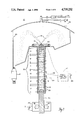
- FIG. 1 is a schematic cross-sectional view of a levitation conduit, a gas atomization work station for re-forming into a powder the molten metal output of the levitation conduit and a chamber for receiving the powder;
- FIG. 2A is an axonometric view of an alternative work station including a rotatable vessel
- FIG. 2B is an elevational cross-sectional view of the work station of FIG. 2A;
- FIG. 3A is an alternative work station showing rapid quenching of molten metal output of the levitation conduit into a thin ribbon by contact with a rapidly rotating chilled wheel;
- FIG. 3B is another work station for quenching the molten metal by contact with a continuously presented chilled surface such as a continuous belt;
- FIG. 4A is a schematic axonometric view of filament formation on a cooling drum with shallow cooling fins
- FIG. 4B is a more detailed view of the cooling fins on the drum along line 4B--4B of FIG. 4A;
- FIG. 5 is a schematic cross-sectional view of an alternative levitation conduit providing molten metal to a side atomization work station
- FIG. 6A is a cross-sectional view along line 6A--6A of the levitation conduit of FIG. 5;
- FIG. 6B is an axonometric view of a water-cooled power coil carrying one electrical phase for the levitation conduit of FIG. 5;
- FIG. 7A is a top plan view with partial cutaway of the work station of FIG. 5;
- FIG. 7B is an elevational cross-sectional view along line 7B--7B of the work station of FIG. 7A;
- FIG. 8 is a schematic elevational cross-sectional view of an alternative jet ring atomization device for the work station of FIG. 5;
- FIG. 9 is a top cross-sectional view of a plurality of solid metals to be introduced into the levitation conduit of FIG. 1 or FIG. 5 to form IN-718 alloy.
- This invention may be accomplished by an apparatus which conveys metal upwardly in a levitation conduit, heats the metal to a temperature above its melting point, and re-forms the molten metal output of the conduit into solid metallic forms.
- the metal while molten is maintained out of pressured contact with the interior surface of the levitation conduit.
- the metal while molten is maintained continually out of contact with the interior of the levitation conduit.
- the metal is atomized into a powder or rapidly solidified into a ribbon or filaments.
- the resulting metallic forms differ in at least one cross-sectional dimension from the cross-sectional dimension of the metal in the levitation conduit.
- the levitated metal is circular in cross-section and has a diameter of x while the molten metal output is rapidly quenched into a ribbon having a width of approximately x but a thickness of y or into a filament having a diameter of z where both y and z are substantially smaller than x.
- Gas atomization and rapid solidification serve to re-form the molten metal without introducing impurities into the molten metal.
- the metal can be introduced in a molten state or, to prevent the metal from entraining impurities in a molten state before it enters the levitation conduit, metal can be introduced in solid form to the input end of the conduit.
- the induced magnetic field levitates the metal and also raises the temperature of the metal above its melting point. Coupled with gas atomization or rapid solidification of molten metal emerging from the conduit, the metal remains entirely free of impurities.
- the levitation conduit can be a vertical column such as that disclosed in Lowry et al., U.S. Pat. No. 4,414,285, hereinafter referred to as Patent '285 and which is incorporated herein by reference, or can be an inclined levitation conduit.
- Patent '285 the shape of the metal that is carefully controlled by the pressure head on the molten metal and the rate of extraction of solidified rod in the process described in Patent '285
- the shape of the molten metal within a levitation conduit in a manufacturing apparatus or method according to this invention is not critical to this invention, as will become apparent.
- the levitation conduit utilized by a method and apparatus according to this invention does not require a heat exchanger or other device for cooling the levitated metal. While one utilizing the process of Patent '285 must be concerned with the inverse relationship between levitation field strength and heat removal rate to prevent unacceptable variations in emerging rod temperature, that concern is not present here.
- Manufacturing apparatus 10 includes levitation conduit 12 which levitates molten metal 14 upwardly to gas atomization work station 16 which re-forms molten metal 14 into particles 18. Solidified particles are collected in hopper 19. Work station 16 is located within chamber 20 from which air is evacuated by pump 22 through outlet 24 and then backfilled to several psi above atmospheric pressure with an inert gas such as argon in canister 26. It is desirable for pump 22 to evacuate chamber 20 to a pressure of 10 -6 mm Hg before backfilling to ensure that little or no oxygen is present to combine with the molten metal.
- Levitation conduit 12 includes graphite liner 28.
- Coil set 30 surrounds graphite liner 28 and induces the magnetic levitation force when six phases are successively shifted 60° apart to provide a smooth field-transporting action.
- the six phases are represented powering the coils in the order -C', B, -A', C, -B', A ascending the column.
- columns 6 through 7, two sets 30 provide 12 coils in an overall levitation section of 6 inches.
- a cooling jacket is not required since the objective of manufacturing apparatus 10 is to raise the temperature of the levitated metal to a temperature at or above its melting point. It is desirable for the magnetic field to induce a superheat, e.g., as much as 200°C. above the liquidus temperature of the metal.
- Patent '285 Another distinction from Patent '285 is that a manufacturing apparatus according to this invention need not control the shape of molten metal 14 within levitation conduit 12.
- the rate at which molten metal is provided to work station 16 is adjusted by varying the polyphase high-frequency power applied to coils 30 or by varying, utilizing potentiometer 31, the rate at which solid metal bar 32 is fed into levitation conduit 12 by feed motor 34.
- potentiometer 31 is varied by an operator to increase feed rate until the operator observes that molten metal 14 enters work station 16 at a desired rate and at a desired level of superheat measured by pyrometer 50.
- feed control circuit 42 In a semi-automated construction, the rate at which rollers 38, 40 feed solid metal 32 is controlled by feed control circuit 42, shown in phantom.
- the feed rate can be manually set using potentiometer 48; alternatively, feed control circuit 42 monitors the temperature of molten metal provided to work station 16 using pyrometer 50 to maintain a desired level of superheat. Since solid metal exhibits a different resistivity than molten metal, control circuit 42 can also monitor the electrical coupling between metal 14 and the coils 30 such as by lines 52, 54.
- FIG. 2A An alternative work station 16a for producing powders is shown in FIG. 2A.
- Vessel 60 is rotated at a speed of 20,000 to 40,000 rpm by motor 62.
- Molten metal provided by levitation conduit l2a strikes the concave inner surface of inverted vessel 60 and is spun off as a powder.
- Molten metal l4a is shown striking the inner surface of vessel 60 in FIG. 2B. It is desirable that the inner surface of vessel 60 consist of a material which is not corrodable by molten metal l4a, e.g., graphite for re-forming liquid copper or aluminum, or cast iron for aluminum-iron alloys.
- a material which is not corrodable by molten metal l4a e.g., graphite for re-forming liquid copper or aluminum, or cast iron for aluminum-iron alloys.
- a manufacturing apparatus is not limited to the formation of powders.
- Molten metal l4b, FIG. 3A impinges upon chilled, rotating drum 64 of work station l6b to form a rapidly solidified ribbon.
- the metal, or melt is chilled to a solid and spun away in a continuous formation operation.
- Acceptable dimensions of the ribbons are 5-25 microns thickness and 1-6 inches width although these dimensions need not be limited to these ranges.
- Drum 64 a quenching wheel, rotates at several thousand rpm and is maintained below 100° C. at its surface by a internally circulated coolant such as water. Cooling of the melt occurs by conduction at a rate which may be as high as 10 8 °K./sec.
- melt 14b emerges from evitation conduit 12b to impinge upon the surface of belt 64a and is swept in the direction of travel indicated by arrow 66.
- the portion the molten film of metal closest to belt 64a solidifies first, quickly followed by the remainder of the film to form solid ribbon 68.
- Drum 64 can have a smooth surface to produce a smooth, flat ribbon; alternatively, surface of drum 64 is patterned to provide a metal which is more easily broken into fragments if needed in a pulverized form.
- Rapidly solidified filaments are produced by work station l6c, FIG. 4A.
- Rotatable drum 70 receives molten metal onto shallow fins 72 from work station l2c and produces filaments 74.
- Fins 72 shown in an enlarged view in FIG. 4B, are continuous about drum 70 and produce filaments having a cross section of approximately 25 microns in diameter. The melt quenches within shallow grooves 73.
- the fins are provided with transverse channels to produc staple length filaments.
- Manufacturing apparatus 80 includes inclined levitation conduit 82 supported by hydraulic lift 84 having pivoting platform 86.
- Control circuit 88 monitors the input rate of solid rod 91 imparted by feed apparatus 90 and the output temperature of melt 96 using pyrometer 92 and commands lift 84 to adjust the angle of incline, arrow 94, to maintain the desired rate of exit of melt 96.
- Inert gas 98 emerging through atomizing device 100 produces particles 101.
- the induced heating such as illustrated in FIG. 8 of Patent '285 resulting from a power level sufficient to levitate the molten metal, is sufficient to melt solid metal fed into the levitation conduit and to heat the metal to a temperature well above its melting point. If additional heating is desired the power level can be increased.
- atomization When using a levitation conduit similar to the levitation column of Patent '285, atomization must commence before the lifting force diminishes below the level required to keep the melt moving upward.
- atomization can be performed on a descending stream of molten metal which can be more finely controlled by adjusting polyphase power input, frequency, conduit incline, or a combination of these parameters.
- Levitation conduit 82 is shown in cross-section in FIG. 6A to reveal melt 96, liner 102, and water cooled coil 104.
- Liner 102 is heavy walled graphite; alternatively, water cooled copper can be used.
- Coil 104 carries the power and is water-cooled to prevent it from melting. While liner 102 is shown in a horseshoe shape, it may more completely envelop the molten meal as illustrated by liner l02a. Liner 102a may completely surround melt 96 as indicated by dashed lines 103, 105 extending from the edges of liner 102.
- Coil 104 for coil section A is shown in an axonometric view in FIG. 6B where water is provided as indicated by arrow 106 and exits as indicated by arrow 108.
- Atomizing device 100 is shown in partial cross section viewed from the top in FIG. 7A and from the side in FIG. 7B.
- Argon or any other, desired gas 98 passes through fan-shaped jets 109, 110 and 112 to disperse molten metal 96 into particles 101. Jet dimensions in relationship to the diameter of the metal stream are chosen for optimum performance as is known to those skilled in the art.
- Atomizing device 100 produces a diverging pattern of powder.
- Conventional gas aomized powder suffers from “satellites”: the converging gas jets cause some particles to collide and agglomerate in groups before their surfaces have cooled sufficiently. This clumping alters the desired particle size distribution obtained.
- a conventional atomizer such as ring atomizing device 100a, FIG. 8, can be used to fragment or otherwise re-form melt 96a. Converging streams of argon emerging from 0.02 to 0.05 inch diameter jets 113 impinge upon molten stream 96a to produce powder 101a.
- metal provided to the input end of the levitation conduit is described above in terms of a solid rod or bar, this is not a limitation of the invention.
- a number of solid metals can be provided continually in a ratio selected to produce an alloy by melting and mixing the metals within a levitation conduit. Homogeneity is assured by arranging the parameters of the levitation conduit such that the metals liquefy a predetermined distance from the exit of the conduit. Levitation is provided by the induction coils which also induce mixing and stirring of the metals.
- the constituent metals 114 of IN-718 alloy are shown in FIG. 9 in cross section within graphite liner 116.
- metals 114 are of high purity and contain almost no non-metallic inclusions.
- Chromium rod Cr obtained in a pure state by the Van Arkel iodide process, for example, is surrounded with nickel Ni coating that is electroplated over rod Cr. Iron Fe is then electroplated or provided as a carbonyl coating over the nickel coating Ni. Molybdenum Mo is then wrapped as a foil over the iron Fe.
- the two other major ingredients, aluminum Al and niobium-titanium Nb-Ti are provided as separate wires.
- the composition by weight percent, density, cross section and dimension of these constituents for liner 116 having a 1-inch bore is shown in Table I.
- Carbon C, manganese Mn, silicon Si and copper Cu can be added as a spray or may be alloyed to wire Al.
- the Nb-Ti wire is assumed to be 85 Nb 15 Ti wire having a density of approximately 8 g/cc. Sixty-five percent of the 1-inch bore or 0.5105 square inch is occupied by the wire and rod composition 114.
- the volume fraction or weight percentage of each constituent is desirable for the volume fraction or weight percentage of each constituent to remain constant as it is introduced into a levitation conduit.
- the metals are introduced as a rigid bundle of wire and rod.
Abstract
Description
                                  TABLE I
__________________________________________________________________________
CROSS-SECTION OF PURE WIRES & RODS TO FORM IN-718
                DENSITY
                      NORMALIZED
                                CROSS-
                                      WIRE OR ROD
       COMPOSITION
                ρ CROSS-SECTION
                                SECTION
                                      DIMENSION*
ELEMENT
       w/o      (g/cc)
                      (w/o/ρ)
                                %     (INCH)   SOURCE
__________________________________________________________________________
Ni     52.5     8.9   5.899     48.63 0.676 ×
                                               Electroplate Over
                                      0.376    Cr Bar
Cr     19.0     7.2   2.639     21.76 0.376.0. Van Arkel Pure Bar
Fe     18.5      7.86 2.354     19.41 0.764 ×
                                               Electroplate Over
                                      0.676    Ni Layer
Nb     5.13     8.57
                   8  0.754     6.22  0.201.0. Cold Hearth Melted
Ti     0.9      4.5                            85Nb--15Ti Alloy
                                               Drawn to Wire
Mo     3.05     10.2  0.299     2.46  0.126.0. Wire or Foil
                                      or
                                      0.010 Foil
Al     0.5      2.7   0. ± 85
                                1.53  0.100.0. Wire or Foil
                                      or
                                      0.005 Foil
C, Mn  0.55     --    --        --    --       Alloy Additions to
Si, Cu Total                                   Al Wire Foil
__________________________________________________________________________
Claims (35)
Priority Applications (3)
| Application Number | Priority Date | Filing Date | Title |
|---|---|---|---|
| US06/819,376 US4735252A (en) | 1986-01-16 | 1986-01-16 | System for reforming levitated molten metal into metallic forms |
| PCT/US1986/002582 WO1987004378A2 (en) | 1986-01-16 | 1986-12-03 | System for reforming levitated molten metal into metallic forms |
| EP87903925A EP0262220A1 (en) | 1986-01-16 | 1986-12-03 | System for reforming levitated molten metal into metallic forms |
Applications Claiming Priority (1)
| Application Number | Priority Date | Filing Date | Title |
|---|---|---|---|
| US06/819,376 US4735252A (en) | 1986-01-16 | 1986-01-16 | System for reforming levitated molten metal into metallic forms |
Publications (1)
| Publication Number | Publication Date |
|---|---|
| US4735252A true US4735252A (en) | 1988-04-05 |
Family
ID=25227982
Family Applications (1)
| Application Number | Title | Priority Date | Filing Date |
|---|---|---|---|
| US06/819,376 Expired - Fee Related US4735252A (en) | 1986-01-16 | 1986-01-16 | System for reforming levitated molten metal into metallic forms |
Country Status (2)
| Country | Link |
|---|---|
| US (1) | US4735252A (en) |
| EP (1) | EP0262220A1 (en) |
Cited By (2)
| Publication number | Priority date | Publication date | Assignee | Title |
|---|---|---|---|---|
| US5837055A (en) * | 1995-05-19 | 1998-11-17 | Daido Tokushuko Kaisha | Levitation melting method and melting and casting method |
| US20140090796A1 (en) * | 2012-09-28 | 2014-04-03 | Theodore A. Waniuk | Continuous amorphous feedstock skull melting |
Citations (5)
| Publication number | Priority date | Publication date | Assignee | Title |
|---|---|---|---|---|
| US3243493A (en) * | 1963-06-17 | 1966-03-29 | Rointan F Bunshah | Method and apparatus for induction melting |
| US3696858A (en) * | 1968-09-24 | 1972-10-10 | Aeg Elotherm Gmbh | Method for casting metered quantities of liquid metals |
| GB2080715A (en) * | 1980-07-02 | 1982-02-10 | Gen Electric | Continuous metal casting method, apparatus and products |
| US4414285A (en) * | 1982-09-30 | 1983-11-08 | General Electric Company | Continuous metal casting method, apparatus and product |
| US4544404A (en) * | 1985-03-12 | 1985-10-01 | Crucible Materials Corporation | Method for atomizing titanium |
-
1986
- 1986-01-16 US US06/819,376 patent/US4735252A/en not_active Expired - Fee Related
- 1986-12-03 EP EP87903925A patent/EP0262220A1/en not_active Withdrawn
Patent Citations (5)
| Publication number | Priority date | Publication date | Assignee | Title |
|---|---|---|---|---|
| US3243493A (en) * | 1963-06-17 | 1966-03-29 | Rointan F Bunshah | Method and apparatus for induction melting |
| US3696858A (en) * | 1968-09-24 | 1972-10-10 | Aeg Elotherm Gmbh | Method for casting metered quantities of liquid metals |
| GB2080715A (en) * | 1980-07-02 | 1982-02-10 | Gen Electric | Continuous metal casting method, apparatus and products |
| US4414285A (en) * | 1982-09-30 | 1983-11-08 | General Electric Company | Continuous metal casting method, apparatus and product |
| US4544404A (en) * | 1985-03-12 | 1985-10-01 | Crucible Materials Corporation | Method for atomizing titanium |
Non-Patent Citations (2)
| Title |
|---|
| Brochure of Ajax Magnethermic, "Dynapour Delivers the Metal", May 1977. |
| Brochure of Ajax Magnethermic, Dynapour Delivers the Metal , May 1977. * |
Cited By (3)
| Publication number | Priority date | Publication date | Assignee | Title |
|---|---|---|---|---|
| US5837055A (en) * | 1995-05-19 | 1998-11-17 | Daido Tokushuko Kaisha | Levitation melting method and melting and casting method |
| US20140090796A1 (en) * | 2012-09-28 | 2014-04-03 | Theodore A. Waniuk | Continuous amorphous feedstock skull melting |
| US8813813B2 (en) * | 2012-09-28 | 2014-08-26 | Apple Inc. | Continuous amorphous feedstock skull melting |
Also Published As
| Publication number | Publication date |
|---|---|
| EP0262220A1 (en) | 1988-04-06 |
| WO1987004378A1 (en) | 1987-07-30 |
Similar Documents
| Publication | Publication Date | Title |
|---|---|---|
| JP2930880B2 (en) | Method and apparatus for producing differential pressure cast metallic glass | |
| EP0471798B1 (en) | Induction skull melt spinning of reactive metal alloys | |
| US5954112A (en) | Manufacturing of large diameter spray formed components using supplemental heating | |
| US6460595B1 (en) | Nucleated casting systems and methods comprising the addition of powders to a casting | |
| EP0420393A1 (en) | System and method for atomizing a titanium-based material | |
| US20060230876A1 (en) | Method for producing alloy ingots | |
| US6368375B1 (en) | Processing of electroslag refined metal | |
| US4523621A (en) | Method for making metallic glass powder | |
| JP4762409B2 (en) | Articles nucleated and cast from clean metal | |
| US5427173A (en) | Induction skull melt spinning of reactive metal alloys | |
| JPH059482B2 (en) | ||
| JPH0270012A (en) | Device and method for manufacture of fine metallic powder | |
| EP0017723B1 (en) | Method and apparatus for making metallic glass powder | |
| US4735252A (en) | System for reforming levitated molten metal into metallic forms | |
| WO1987004378A2 (en) | System for reforming levitated molten metal into metallic forms | |
| Zhang et al. | Preparation methods of high-entropy materials | |
| US4687606A (en) | Metalloid precursor powder and method of making same | |
| EP0131797B1 (en) | Method of making composite material of matrix metal and fine metallic particles dispersed therein | |
| Aller et al. | Rotating atomization processes of reactive and refractory alloys | |
| JPH06116609A (en) | Production of metal powder | |
| JPH03180432A (en) | Melting method and melting device of metal | |
| JP2550064B2 (en) | Method and apparatus for manufacturing alloy ingot | |
| JP4959897B2 (en) | Casting apparatus and method with an eccentric source of liquid metal | |
| JPH01222002A (en) | Manufacture of intermetallic compound powder | |
| JPS6092432A (en) | Method and device for plasma arc melting |
Legal Events
| Date | Code | Title | Description |
|---|---|---|---|
| AS | Assignment |
Owner name: NUCLEAR METALS, INC., 2229 MAIN STREET, CONCORD, M Free format text: ASSIGNMENT OF ASSIGNORS INTEREST.;ASSIGNOR:ROBERTS, PETER R.;REEL/FRAME:004507/0768 Effective date: 19860102 |
|
| FPAY | Fee payment |
Year of fee payment: 4 |
|
| REMI | Maintenance fee reminder mailed | ||
| LAPS | Lapse for failure to pay maintenance fees | ||
| FP | Lapsed due to failure to pay maintenance fee |
Effective date: 19960410 |
|
| AS | Assignment |
Owner name: STARMET CORPORATION, MASSACHUSETTS Free format text: CHANGE OF NAME;ASSIGNOR:NUCLEAR METALS, INC.;REEL/FRAME:008876/0463 Effective date: 19971001 |
|
| AS | Assignment |
Owner name: STATE STREET BANK AND TRUST COMPANY, MASSACHUSETTS Free format text: SECURITY INTEREST;ASSIGNORS:STARMET CORPORATION;STARMET POWDERS, LLC;REEL/FRAME:009845/0510 Effective date: 19990224 |
|
| AS | Assignment |
Owner name: STATE STREET BANK AND TRUST COMPANY, MASSACHUSETTS Free format text: ASSIGNMENT OF ASSIGNORS INTEREST;ASSIGNORS:STARMET CORPORATION (F/K/A NUCLEAR METALS, INC.);STARMET POWDERS, LLC;STARMET AEROCAST, LLC;AND OTHERS;REEL/FRAME:011934/0912 Effective date: 20010330 |
|
| STCH | Information on status: patent discontinuation |
Free format text: PATENT EXPIRED DUE TO NONPAYMENT OF MAINTENANCE FEES UNDER 37 CFR 1.362 |