JP4959897B2 - Casting apparatus and method with an eccentric source of liquid metal - Google Patents
Casting apparatus and method with an eccentric source of liquid metal Download PDFInfo
- Publication number
- JP4959897B2 JP4959897B2 JP2001561468A JP2001561468A JP4959897B2 JP 4959897 B2 JP4959897 B2 JP 4959897B2 JP 2001561468 A JP2001561468 A JP 2001561468A JP 2001561468 A JP2001561468 A JP 2001561468A JP 4959897 B2 JP4959897 B2 JP 4959897B2
- Authority
- JP
- Japan
- Prior art keywords
- casting
- metal
- source
- liquid metal
- refining
- Prior art date
- Legal status (The legal status is an assumption and is not a legal conclusion. Google has not performed a legal analysis and makes no representation as to the accuracy of the status listed.)
- Expired - Fee Related
Links
- 238000005266 casting Methods 0.000 title claims description 204
- 229910001338 liquidmetal Inorganic materials 0.000 title claims description 93
- 238000000034 method Methods 0.000 title claims description 28
- 229910052751 metal Inorganic materials 0.000 claims description 111
- 239000002184 metal Substances 0.000 claims description 111
- 238000007670 refining Methods 0.000 claims description 97
- 230000006911 nucleation Effects 0.000 claims description 55
- 238000010899 nucleation Methods 0.000 claims description 55
- 239000007787 solid Substances 0.000 claims description 29
- 239000002893 slag Substances 0.000 claims description 22
- 150000003568 thioethers Chemical class 0.000 claims description 12
- PXHVJJICTQNCMI-UHFFFAOYSA-N Nickel Chemical compound [Ni] PXHVJJICTQNCMI-UHFFFAOYSA-N 0.000 claims description 10
- 230000008569 process Effects 0.000 claims description 9
- 239000007788 liquid Substances 0.000 claims description 8
- 230000007547 defect Effects 0.000 claims description 6
- 238000005204 segregation Methods 0.000 claims description 6
- 239000010936 titanium Substances 0.000 claims description 5
- XEEYBQQBJWHFJM-UHFFFAOYSA-N Iron Chemical compound [Fe] XEEYBQQBJWHFJM-UHFFFAOYSA-N 0.000 claims description 4
- 239000007791 liquid phase Substances 0.000 claims description 4
- 238000002844 melting Methods 0.000 claims description 4
- 230000008018 melting Effects 0.000 claims description 4
- 229910052759 nickel Inorganic materials 0.000 claims description 4
- RTAQQCXQSZGOHL-UHFFFAOYSA-N Titanium Chemical compound [Ti] RTAQQCXQSZGOHL-UHFFFAOYSA-N 0.000 claims description 3
- 239000010941 cobalt Substances 0.000 claims description 3
- 229910017052 cobalt Inorganic materials 0.000 claims description 3
- GUTLYIVDDKVIGB-UHFFFAOYSA-N cobalt atom Chemical compound [Co] GUTLYIVDDKVIGB-UHFFFAOYSA-N 0.000 claims description 3
- 230000009467 reduction Effects 0.000 claims description 3
- 229910052719 titanium Inorganic materials 0.000 claims description 3
- 230000006378 damage Effects 0.000 claims description 2
- 239000010953 base metal Substances 0.000 claims 1
- 238000007599 discharging Methods 0.000 claims 1
- 238000003780 insertion Methods 0.000 claims 1
- 230000037431 insertion Effects 0.000 claims 1
- 229910052742 iron Inorganic materials 0.000 claims 1
- 239000000843 powder Substances 0.000 claims 1
- 210000003625 skull Anatomy 0.000 description 26
- 238000001816 cooling Methods 0.000 description 22
- 239000000047 product Substances 0.000 description 18
- 239000007789 gas Substances 0.000 description 16
- 239000002826 coolant Substances 0.000 description 15
- 238000010438 heat treatment Methods 0.000 description 15
- 238000004320 controlled atmosphere Methods 0.000 description 12
- 230000006698 induction Effects 0.000 description 11
- 230000001276 controlling effect Effects 0.000 description 9
- 239000012535 impurity Substances 0.000 description 9
- 238000004519 manufacturing process Methods 0.000 description 9
- 238000007711 solidification Methods 0.000 description 9
- 230000008023 solidification Effects 0.000 description 9
- IJGRMHOSHXDMSA-UHFFFAOYSA-N Atomic nitrogen Chemical compound N#N IJGRMHOSHXDMSA-UHFFFAOYSA-N 0.000 description 8
- 229910045601 alloy Inorganic materials 0.000 description 6
- 239000000956 alloy Substances 0.000 description 6
- 238000005058 metal casting Methods 0.000 description 6
- 230000036961 partial effect Effects 0.000 description 6
- 229910000601 superalloy Inorganic materials 0.000 description 6
- XLYOFNOQVPJJNP-UHFFFAOYSA-N water Substances O XLYOFNOQVPJJNP-UHFFFAOYSA-N 0.000 description 6
- 230000000670 limiting effect Effects 0.000 description 5
- 239000000463 material Substances 0.000 description 5
- 239000007921 spray Substances 0.000 description 5
- 238000010313 vacuum arc remelting Methods 0.000 description 5
- XKRFYHLGVUSROY-UHFFFAOYSA-N Argon Chemical compound [Ar] XKRFYHLGVUSROY-UHFFFAOYSA-N 0.000 description 4
- 230000002411 adverse Effects 0.000 description 4
- 239000013078 crystal Substances 0.000 description 4
- 150000002739 metals Chemical class 0.000 description 4
- 239000000203 mixture Substances 0.000 description 4
- 229910052757 nitrogen Inorganic materials 0.000 description 4
- 230000003247 decreasing effect Effects 0.000 description 3
- 230000001965 increasing effect Effects 0.000 description 3
- 230000007246 mechanism Effects 0.000 description 3
- 230000002829 reductive effect Effects 0.000 description 3
- OKTJSMMVPCPJKN-UHFFFAOYSA-N Carbon Chemical compound [C] OKTJSMMVPCPJKN-UHFFFAOYSA-N 0.000 description 2
- RYGMFSIKBFXOCR-UHFFFAOYSA-N Copper Chemical compound [Cu] RYGMFSIKBFXOCR-UHFFFAOYSA-N 0.000 description 2
- 229910052786 argon Inorganic materials 0.000 description 2
- 239000004020 conductor Substances 0.000 description 2
- 239000000498 cooling water Substances 0.000 description 2
- 229910052802 copper Inorganic materials 0.000 description 2
- 239000010949 copper Substances 0.000 description 2
- 238000005336 cracking Methods 0.000 description 2
- 229910002804 graphite Inorganic materials 0.000 description 2
- 239000010439 graphite Substances 0.000 description 2
- 238000009413 insulation Methods 0.000 description 2
- 239000002245 particle Substances 0.000 description 2
- 229910001018 Cast iron Inorganic materials 0.000 description 1
- 241000237858 Gastropoda Species 0.000 description 1
- UFHFLCQGNIYNRP-UHFFFAOYSA-N Hydrogen Chemical compound [H][H] UFHFLCQGNIYNRP-UHFFFAOYSA-N 0.000 description 1
- FYYHWMGAXLPEAU-UHFFFAOYSA-N Magnesium Chemical compound [Mg] FYYHWMGAXLPEAU-UHFFFAOYSA-N 0.000 description 1
- 238000003723 Smelting Methods 0.000 description 1
- 229910000831 Steel Inorganic materials 0.000 description 1
- 230000009471 action Effects 0.000 description 1
- 229910052782 aluminium Inorganic materials 0.000 description 1
- XAGFODPZIPBFFR-UHFFFAOYSA-N aluminium Chemical compound [Al] XAGFODPZIPBFFR-UHFFFAOYSA-N 0.000 description 1
- 238000013459 approach Methods 0.000 description 1
- -1 but not limited to Substances 0.000 description 1
- 229910010293 ceramic material Inorganic materials 0.000 description 1
- 239000000470 constituent Substances 0.000 description 1
- 238000009749 continuous casting Methods 0.000 description 1
- 230000001627 detrimental effect Effects 0.000 description 1
- 238000009826 distribution Methods 0.000 description 1
- 230000005684 electric field Effects 0.000 description 1
- 239000000284 extract Substances 0.000 description 1
- 239000012467 final product Substances 0.000 description 1
- 238000005242 forging Methods 0.000 description 1
- 239000001257 hydrogen Substances 0.000 description 1
- 229910052739 hydrogen Inorganic materials 0.000 description 1
- 230000001939 inductive effect Effects 0.000 description 1
- 239000011810 insulating material Substances 0.000 description 1
- 238000002955 isolation Methods 0.000 description 1
- 229910052749 magnesium Inorganic materials 0.000 description 1
- 239000011777 magnesium Substances 0.000 description 1
- 239000000155 melt Substances 0.000 description 1
- 239000007769 metal material Substances 0.000 description 1
- 229910052756 noble gas Inorganic materials 0.000 description 1
- 150000002835 noble gases Chemical class 0.000 description 1
- 230000003647 oxidation Effects 0.000 description 1
- 238000007254 oxidation reaction Methods 0.000 description 1
- 239000011148 porous material Substances 0.000 description 1
- 239000012255 powdered metal Substances 0.000 description 1
- 238000000746 purification Methods 0.000 description 1
- 239000002994 raw material Substances 0.000 description 1
- 230000001105 regulatory effect Effects 0.000 description 1
- 238000005507 spraying Methods 0.000 description 1
- 239000010959 steel Substances 0.000 description 1
- 230000000930 thermomechanical effect Effects 0.000 description 1
- 210000001519 tissue Anatomy 0.000 description 1
Images


Classifications
-
- B—PERFORMING OPERATIONS; TRANSPORTING
- B22—CASTING; POWDER METALLURGY
- B22D—CASTING OF METALS; CASTING OF OTHER SUBSTANCES BY THE SAME PROCESSES OR DEVICES
- B22D37/00—Controlling or regulating the pouring of molten metal from a casting melt-holding vessel
-
- B—PERFORMING OPERATIONS; TRANSPORTING
- B22—CASTING; POWDER METALLURGY
- B22D—CASTING OF METALS; CASTING OF OTHER SUBSTANCES BY THE SAME PROCESSES OR DEVICES
- B22D23/00—Casting processes not provided for in groups B22D1/00 - B22D21/00
- B22D23/06—Melting-down metal, e.g. metal particles, in the mould
- B22D23/10—Electroslag casting
-
- B—PERFORMING OPERATIONS; TRANSPORTING
- B22—CASTING; POWDER METALLURGY
- B22F—WORKING METALLIC POWDER; MANUFACTURE OF ARTICLES FROM METALLIC POWDER; MAKING METALLIC POWDER; APPARATUS OR DEVICES SPECIALLY ADAPTED FOR METALLIC POWDER
- B22F3/00—Manufacture of workpieces or articles from metallic powder characterised by the manner of compacting or sintering; Apparatus specially adapted therefor ; Presses and furnaces
- B22F3/115—Manufacture of workpieces or articles from metallic powder characterised by the manner of compacting or sintering; Apparatus specially adapted therefor ; Presses and furnaces by spraying molten metal, i.e. spray sintering, spray casting
-
- C—CHEMISTRY; METALLURGY
- C23—COATING METALLIC MATERIAL; COATING MATERIAL WITH METALLIC MATERIAL; CHEMICAL SURFACE TREATMENT; DIFFUSION TREATMENT OF METALLIC MATERIAL; COATING BY VACUUM EVAPORATION, BY SPUTTERING, BY ION IMPLANTATION OR BY CHEMICAL VAPOUR DEPOSITION, IN GENERAL; INHIBITING CORROSION OF METALLIC MATERIAL OR INCRUSTATION IN GENERAL
- C23C—COATING METALLIC MATERIAL; COATING MATERIAL WITH METALLIC MATERIAL; SURFACE TREATMENT OF METALLIC MATERIAL BY DIFFUSION INTO THE SURFACE, BY CHEMICAL CONVERSION OR SUBSTITUTION; COATING BY VACUUM EVAPORATION, BY SPUTTERING, BY ION IMPLANTATION OR BY CHEMICAL VAPOUR DEPOSITION, IN GENERAL
- C23C4/00—Coating by spraying the coating material in the molten state, e.g. by flame, plasma or electric discharge
- C23C4/12—Coating by spraying the coating material in the molten state, e.g. by flame, plasma or electric discharge characterised by the method of spraying
- C23C4/123—Spraying molten metal
-
- B—PERFORMING OPERATIONS; TRANSPORTING
- B22—CASTING; POWDER METALLURGY
- B22F—WORKING METALLIC POWDER; MANUFACTURE OF ARTICLES FROM METALLIC POWDER; MAKING METALLIC POWDER; APPARATUS OR DEVICES SPECIALLY ADAPTED FOR METALLIC POWDER
- B22F9/00—Making metallic powder or suspensions thereof
- B22F9/02—Making metallic powder or suspensions thereof using physical processes
- B22F9/06—Making metallic powder or suspensions thereof using physical processes starting from liquid material
- B22F9/08—Making metallic powder or suspensions thereof using physical processes starting from liquid material by casting, e.g. through sieves or in water, by atomising or spraying
- B22F9/082—Making metallic powder or suspensions thereof using physical processes starting from liquid material by casting, e.g. through sieves or in water, by atomising or spraying atomising using a fluid
- B22F2009/0848—Melting process before atomisation
- B22F2009/0852—Electroslag melting
-
- B—PERFORMING OPERATIONS; TRANSPORTING
- B22—CASTING; POWDER METALLURGY
- B22F—WORKING METALLIC POWDER; MANUFACTURE OF ARTICLES FROM METALLIC POWDER; MAKING METALLIC POWDER; APPARATUS OR DEVICES SPECIALLY ADAPTED FOR METALLIC POWDER
- B22F9/00—Making metallic powder or suspensions thereof
- B22F9/02—Making metallic powder or suspensions thereof using physical processes
- B22F9/06—Making metallic powder or suspensions thereof using physical processes starting from liquid material
- B22F9/08—Making metallic powder or suspensions thereof using physical processes starting from liquid material by casting, e.g. through sieves or in water, by atomising or spraying
- B22F9/082—Making metallic powder or suspensions thereof using physical processes starting from liquid material by casting, e.g. through sieves or in water, by atomising or spraying atomising using a fluid
- B22F2009/0848—Melting process before atomisation
- B22F2009/0856—Skull melting
-
- B—PERFORMING OPERATIONS; TRANSPORTING
- B22—CASTING; POWDER METALLURGY
- B22F—WORKING METALLIC POWDER; MANUFACTURE OF ARTICLES FROM METALLIC POWDER; MAKING METALLIC POWDER; APPARATUS OR DEVICES SPECIALLY ADAPTED FOR METALLIC POWDER
- B22F2998/00—Supplementary information concerning processes or compositions relating to powder metallurgy
Landscapes
- Engineering & Computer Science (AREA)
- Mechanical Engineering (AREA)
- Chemical & Material Sciences (AREA)
- Manufacturing & Machinery (AREA)
- Physics & Mathematics (AREA)
- Plasma & Fusion (AREA)
- Chemical Kinetics & Catalysis (AREA)
- Materials Engineering (AREA)
- Metallurgy (AREA)
- Organic Chemistry (AREA)
- Manufacture And Refinement Of Metals (AREA)
Description
【0001】
【発明の背景】
本発明は鋳造装置及び方法に関する。具体的には、本発明は清浄金属核生成鋳造装置及び方法のための液体金属の離心供給源を備える鋳造装置及び方法に関する。
【0002】
鉄(Fe)基、ニッケル(Ni)基、チタン(Ti)基及びコバルト(Co)基合金のような金属は、微細粒ミクロ組織、均質性及び実質的に欠陥のない組成が望まれるタービン部品用途に多用される。超合金の製造コストは高いので、超合金の鋳造品及びインゴットに問題があるのは望ましくなく、こうした問題の結末は特にタービン部品へと加工されるインゴットで有害である。従来の鋳造品製造装置では、鋳造品から製造される部品に不都合な結果を生じかねない不純物、夾雑物その他の成分の量を低減させることが試みられていた。しかし、比較的大量の金属(例えば超合金)の処理及び精錬には、均質で欠陥のない組織を得る上で多くの問題が伴う。これらの問題の原因の少なくとも一部として、インゴットの鋳造及び凝固時の金属量の多さが考えられる。
【0003】
業界で公知の鋳造装置には、エレクトロスラグ精錬(ESR)装置並びに低温誘導案内(CIG)構造物を備えたエレクトロスラグ精錬装置がある。エレクトロスラグ精錬装置は当技術分野で公知であり、例えばすべて本願出願人に譲渡された米国特許第5160532号、同第5310165号、同第5325906号、同第5332197号、同第5348566号、同第5366206号、同第5472177号、同第5480097号、同第5769151号、同第5809057号及び同第5810066号に開示されている。これらのエレクトロスラグ精錬装置は鋳造品の製造に極めて有効であるが、鋳造品の液相線部分の深さの制御手段は全く含んでいない。
【0004】
超合金でよくみられる問題の一つは、鋳造品の製造に用いられる鋳造装置の種類に関係なく、鋳造品の液相線部分(当技術分野では「溶湯プール」として知られる)の深さの制御である。例えば、鋳造品の結晶粒度及びミクロ組織は、凝固時の鋳造品の液相線部分の深さによって左右されることがある。液相線部分が深いと、成分マクロ偏析を引起こし、さらに有害なミクロ組織(例えば、微細粒ミクロ組織でないミクロ組織)や、元素偏析を起こして不均質組織を生じるおそれがある。こうした深い溶湯プールの問題を解決するため、エレクトロスラグ精錬プロセスと併せて後処理作業を用いることが提唱されている。こうした後処理には、真空アーク再溶解(VAR)がある。真空アーク再溶解は、真空アーク工程でインゴットを処理して比較的浅い溶湯プールが形成されたときに開始し、改善されたミクロ組織を生じさせるが、かかるミクロ組織は水素含量が低下していることもある。真空アーク精錬プロセスに続いて、得られたインゴットを機械的に加工して望ましい微細粒ミクロ組織を有する金属素材を得る。かかる機械的加工としては、鍛造加工、引抜き加工及び熱処理の組合せがある。かかる熱機械的処理には、高価な大規模設備だけでなく、多大なエネルギー入力も必要とされる。
【0005】
望ましい鋳造品ミクロ組織を得る試みは、米国特許第5381847号で提唱されている。米国特許第5381847号には、鉛直鋳造プロセスで樹枝状結晶成長を抑制して結晶粒ミクロ組織を制御することが試みられている。この方法は幾つかの用途に有用なミクロ組織を与え得るが、米国特許第5381847号記載の鉛直鋳造プロセスでは、液相線部分の深さを制御しない。
【0006】
そこで、鋳造品の液相線部分の深さを制御する金属鋳造方法を提供する必要性が存在する。鋳造品の液相線部分の深さの制御は、比較的均質な微細粒ミクロ組織を有する鋳造品を生ずるはずである。さらに、比較的均質な微細粒ミクロ組織を有する鋳造品を製造すべく鋳造品の液相線部分の深さを制御する金属鋳造装置を提供する必要性も存在する。さらに、タービン部品用に、酸化物を実質的に含まない鋳造品を製造すべく鋳造品の液相線部分の深さを制御する金属鋳造プロセス及び装置を提供する必要性も存在する。
【0007】
【発明の概要】
本発明の一態様では、鋳造装置を開示する。この鋳造装置は、当該鋳造装置で形成中の鋳造品に供給される精錬液体金属の離心供給源を含む。鋳造品は、精錬液体金属を受入れる液相線部分と凝固部分からなり、実質的に酸化物と硫化物を含まず偏析欠陥のない微細粒均質ミクロ組織を有する。本鋳造装置は、精錬によって酸化物と硫化物が除去された精錬液体金属の供給源と、鋳造品を形成するための核生成鋳造装置とを含む。精錬液体金属の離心供給源は、精錬液体金属に含まれる熱を液相線部分全体に分散させて鋳造品の液相線部分の深さを減少させるため、鋳造品の中心線から外れて核生成鋳造装置に供給される。
【0008】
本発明の別の態様では、当該鋳造方法で形成中の鋳造品に供給される精錬液体金属の離心供給源を含む鋳造方法が提供される。鋳造品は、精錬液体金属を受入れる液相線部分と凝固部分からなり、実質的に酸化物と硫化物を含まず偏析欠陥のない微細粒均質ミクロ組織を有する。本鋳造方法は、精錬によって酸化物と硫化物が除去された精錬液体金属の供給源を用意する工程と、核生成鋳造で鋳造品を形成する工程とを含む。精錬液体金属の供給源を用意する工程は、精錬液体金属に含まれる熱を液相線部分全体に分散させて鋳造品の液相線部分の深さを減少させるため、鋳造品の中心線から外れて投入される精錬液体金属の供給源を供給することを含む。
【0009】
本発明の上記その他の態様、利点及び顕著な特徴は、本発明の実施形態について開示した以下の詳細な説明を添付の図面と併せて参照することで明らかとなろう。図面全体を通して、類似部品は類似の符号で示した。
【0010】
【発明の実施の形態】
鋳造品を製造するための鋳造装置及び方法は、鋳造品への液体金属の離心供給源を設けることにより鋳造品の液相線部分の深さを制御する。鋳造品への液体金属の離心供給源は、鋳造品の液相線部分の中心にもたらされる熱量を低減する。液相線部分の中心で熱量が低減するのは、液体金属源の温度が概して鋳造品の液相線部分と鋳造品の凝固部分からなる鋳造品の残部の温度よりも高いからである。鋳造品の残部の温度が低いのは、凝固用鋳型への導入時に液体金属源から熱が失われることによる。鋳造品の液相線部分の深さを制御すれば、比較的均質な微細粒ミクロ組織を有する鋳造品が生ずるはずである。さらに、鋳造品の液相線部分の深さを制御すれば、タービン部品用の、実質的に酸化物を含まない比較的均質な微細粒ミクロ組織を有する鋳造品を与えるはずである。「実質的に含まない」という用語は、材料中のいかなる成分も材料に悪影響を与えない(例えば、強度及びその関連特性に関して)ことを意味する。
【0011】
液体金属の離心供給源を備える鋳造装置は適宜どんな鋳造装置であってもよい。かかる鋳造装置には、エレクトロスラグ精錬(ESR)装置、低温誘導案内(CIG)装置を備えたエレクトロスラグ精錬装置、精錬液体金属を核生成(鉛直)鋳造装置に供給するESR/CIG装置、核生成鋳造装置に精錬金属源を供給するもの、その他適当なタイプの鋳造装置がある。以下の説明では、本発明に係る、鋳造品に供給される液体金属の離心供給源を備える例示的な鋳造装置について説明するが、これは本発明を限定するものではない。
【0012】
例えば、液体金属の離心供給源を備える非限定的な鋳造装置は、本願出願人に付与された上記米国特許に開示されているような低温誘導案内(CIG)装置と協働するエレクトロスラグ精錬装置を含むものでもよい。本発明に係る鋳造品に供給される液体金属の離心供給源は、上述の通り適宜どんな精錬金属供給源に由来するものでもよい。液体金属離心供給源用の精錬金属供給源は、真空アーク再溶解(VAR)装置、真空誘導加熱融解(VIR)装置、低温誘導案内(CIG)装置を備える又は備えていない(上述のような)エレクトロスラグ精錬(ESR)装置、その他金属原料の精製に関する装置を含むものでよい。
【0013】
鋳造品に供給される液体金属の離心供給源を備える別の非限定的な核生成鋳造装置には、複数の溶融金属液滴を生成させて冷却域を通過させる装置を含むものがあり、冷却域は、平均して各液滴の最大約30体積%までを凝固させるのに十分な長さに形成される。液滴は次いで鋳型に入り、金属液滴の凝固は鋳型内で完了する。液滴の約30体積%未満が固体状態のときは、液滴は液体としての特性を保持しており、鋳型内で容易に流動する。上記の供給源は単なる例示にすぎず、本発明を限定するものではない。
【0014】
液体金属の離心供給源を備える鋳造装置は鋳造品に均質微細粒ミクロ組織を生じ、鋳造品はタービン部品用途に多用される多く金属及び合金(特に限定されないが、例えばニッケル(Ni)基超合金、コバルト(Co)基超合金、鉄(Fe)基合金及びチタン(Ti)基合金)から形成し得る。かかる鋳造品は、均質な微細粒ミクロ組織のため、少ない加工及び熱処理工程で最終鋳造品のビレットへと加工することもできるし、或いは直接鍛造することもできる。従って、かかる鋳造品は、特に限定されないが、ディスク、ロータ、動翼、静翼、ホイール、バケット、リング、軸、ホイールその他の同様の構成要素などの回転装置用途及びその他のタービン部品用途を始めとする数多くの用途に使用できる。以下、鋳造品から製造したタービン部品に関して説明するが、これは本発明の技術的範囲に属する用途の例示にすぎない。
【0015】
図1は、例示的な鋳造装置3(例えば、清浄金属核生成鋳造装置3)の非限定的な半模式的部分断面立面図を示し、エレクトロスラグ精錬装置1と核生成鋳造装置2とを含んでいる。鋳造装置3内の鋳造品に供給される液体金属の離心供給源について、まず図1を参照して包括的用語で説明し、次に、本発明の理解を図るべく具体的なエレクトロスラグ精錬装置1及び核生成鋳造装置2について説明する。
【0016】
図1は、本発明に係る鋳造品に供給される液体金属の離心供給源を備える鋳造装置を概略的に示す。図1では、液体金属の離心供給源300は鋳造品145の液相線部分148に供給される。液体金属の離心供給源300は、スプレー138(例えば、特に限定されないが当技術分野で公知のアトマイザアセンブリで形成されるスプレー)として供給される。液体金属源は鋳造品145の中心線350から外れて供給される。液体金属源を中心から外すと、通常深さが最大となる鋳造品の液相線部分の中心部から離れた位置に金属源が配置される。そこで、液体金属供給源に含まれる熱は液相線部分148の中心に直接供給されずに分散され、液相線部分148の深さが最大となる領域にもたらされる熱量が減る。液体金属供給源からの熱は、液相線部分148の中心部ではなく液相線部分148全体に拡散する。
【0017】
鋳造品145は、回転鋳型146(例えば、両頭矢印600で示される両方向に回転する鋳型)内で形成し得る。回転鋳型146は、液相線部分148全体の大部分を液体金属の離心供給源300に提示する。従って、供給される液体金属に存在する熱は鋳造品145の液相線部分148全体にさらに分配される。このような分配は、鋳造品の液相線部分148の固体状態への凝固をさらに促進する。本発明に係る液体金属の離心供給源を備える鋳造装置の特徴については、以下の本発明の例示的実施形態に関する説明でさらに詳しく説明する。
【0018】
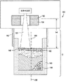
図2は、本発明に係る例示的な鋳造装置3を示す。図2では、清浄金属核生成鋳造装置3及び清浄金属核生成鋳造プロセス用の清浄精錬液体金属は、エレクトロスラグ精錬装置1によって提供し得る。精錬液体金属は、核生成鋳造装置2に供給し得る。エレクトロスラグ精錬装置1と核生成鋳造装置2は協働して清浄金属核生成鋳造装置3を構成し、清浄金属核生成鋳造装置3は鋳造品を形成する。図2〜4は、図1に示す構成要素の細部を示す。本発明に関する以下の説明では清浄金属核生成鋳造装置について述べるが、これは単なる例示にすぎず、本発明を限定するものではない。部分溶融/部分凝固金属液滴(以下「半固形液滴」という。)は鋳型146に集められる。鋳型は、図2の破線で示すような、側壁と底壁を有する単一の一体鋳型からなるものでもよい。別法として、鋳型は鋳型146の側壁から引離すことのできる伸縮式底板246を含む引取り式鋳型からなるものでもよい。本発明に関する以下の説明では、鋳型の非限定的な例として引取り式鋳型について述べるが、本発明を限定するものではない。伸縮式底板246を軸241に連結すれば、底板を側壁から矢印242の方向に移動させることができる。さらに、軸241で伸縮式底板246を矢印243の方向に回転させれば、鋳型の大部分を後述の冷却装置に向けることができる。固形分体積分率が粘度変曲点未満であれば、半固形液滴は液体の様に挙動し、半固形液滴は十分な流動性を示して鋳型の形状に順応する。一般に、粘度変曲点を規定する固形分体積分率の上限は約40体積%未満である。例示的な固形分体積分率は約5〜約40体積%の範囲内にあり、約15〜約30体積%の範囲内の固形分体積分率は粘度変曲点に悪影響を及ぼさない。
【0019】
エレクトロスラグ精錬装置1では、精錬すべき金属の消耗電極24をエレクトロスラグ精錬装置1に直接導入し、消耗電極24を精錬して清浄精錬金属溶湯46(以下「清浄金属」という。)を生じさせる。消耗電極24としてのエレクトロスラグ精錬装置1用金属源は単なる例示にすぎず、本発明の技術的範囲には、特に限定されないが、インゴット、金属溶湯、粉末金属及びこれらの組合せを含む金属源が包含される。消耗電極に関して本発明を説明するが、これは単なる例示にすぎず、本発明を限定するものではない。清浄金属46は、エレクトロスラグ精錬装置1の下方に取付けられた低温炉床構造物40に収容され保持される。清浄金属46は、低温炉床構造物40の下方に配置されたコールドフィンガオリフィス構造物80を通して低温炉床構造物40から排出される。
【0020】
鋳造品に供給される液体金属の離心供給源を備えたエレクトロスラグ精錬装置1は、金属のエレクトロスラグ精錬速度及び低温炉床構造物40への精錬金属の送出速度がコールドフィンガオリフィス構造物80のオリフィス81を通しての低温炉床構造物40からの溶融金属46の排出速度に近似していれば、清浄金属46の供給について実質的に定常運転をもたらす。そこで、清浄金属核生成鋳造方法は長期間連続して運転でき、大量の金属を処理できる。別法として、清浄金属核生成鋳造方法は清浄金属核生成鋳造装置3のいずれか1以上の構成要素の間欠運転によって間欠的に運転することもできる。
【0021】
エレクトロスラグ精錬装置1からコールドフィンガオリフィス構造物80を通して清浄金属46が流出すると、核生成鋳造装置2へと流入する。清浄金属46をさらに加工して精錬金属の比較的大形のインゴットを製造してもよい。別法として、清浄金属46を加工して小形の鋳造品、インゴット又は鋳造品を製造してもよいし、連続鋳造品としてもよい。清浄金属核生成鋳造方法では、望ましい材料特性を有する金属鋳造品の製造に従前必要とされていた上記のような精錬及び加工作業の多くが不要となる。
【0022】
図2には、鉛直運動制御装置10を略示する。鉛直運動制御装置10は鉛直支持体14に取付けられたボックス12を含んでいて、ボックス12には特に限定されないがモータその他の機構のような動力装置(図示せず)が収容される。動力装置は、ねじ部材16に回転運動を与えるように構成される。インゴット支持構造物20は、ねじ部材16と一端でねじ係合した部材(特に限定されないが、例えば部材22)を含む。部材22はその他端において、特に限定されないがボルト26などの適当な連結手段によって消耗電極24を支持する。
【0023】
図2に、鉛直運動制御装置10を略示する。鉛直運動制御装置10は鉛直支持体14に取付けられたボックス12を含んでいて、ボックス12には特に限定されないがモータその他の機構のような動力装置(図示せず)が収容される。動力装置は、ねじ部材16に回転運動を与えるように構成される。インゴット支持構造物20は、ねじ部材16と一端でねじ係合した部材(特に限定されないが、例えば部材22)を含む。部材22はその他端において、特に限定されないがボルト26などの適当な連結手段によって消耗電極24を支持する。
【0024】
エレクトロスラグ精錬構造物30は、特に限定されないが水のような適当な冷却材で冷却される溶湯溜め32を含む。溶湯溜め32は溶融スラグ34を含んでおり、過剰のスラグ34は固体スラグ粒子36として示してある。清浄金属核生成鋳造プロセスに使用されるスラグの組成は処理すべき金属に応じて異なる。後述の通り、内壁82の外側を流れる冷却材の冷却作用により、溶湯溜め32の内壁82の内面にスラグスカル75を形成し得る。
【0025】
エレクトロスラグ精錬構造物30の下方には低温炉床構造物40(図2〜図4)が取付けられる。低温炉床構造物40は、水などの適当な冷却材で冷却された炉床42を含む。炉床42は、凝固した精錬金属のスカル44と精錬液体金属46とを収容している。溶湯溜め32は、炉床42と一体に形成してもよい。別法として、溶湯溜め32と炉床42を別個のユニットとして形成し、それらを連結してエレクトロスラグ精錬装置1を形成してもよい。コールドフィンガオリフィス構造物80にはエレクトロスラグ精錬装置1の底部オリフィス81が設けられているが、これについては図3と図4を参照して説明する。エレクトロスラグ精錬装置1で精錬され、酸化物、硫化物その他の夾雑物を実質的に含まない清浄金属46は、エレクトロスラグ精錬装置1を横断してコールドフィンガオリフィス構造物80のオリフィス81から流出する。
【0026】
電源構造物70は、エレクトロスラグ精錬装置1に精錬電流を供給する。電源構造物70は、電力供給制御機構74を含んでいてもよい。部材22に電流を伝え、ひいては消耗電極24へと電流を伝えることのできる電気導体76で電源構造物70を部材22に接続する。導体78を溶湯溜め32に接続すれば、エレクトロスラグ精錬装置1の電源構造物70の回路が完成する。
【0027】
図2は、エレクトロスラグ精錬構造物30及び低温炉床構造物40の部分断面図であり、エレクトロスラグ精錬構造物30は溶湯溜め32の上方部分を画成し、低温炉床構造物40は溶湯溜め32の下方部分42を画成する。一般に、溶湯溜め32は内壁82と外壁84を有する二重壁の溶湯溜めからなる。内壁82と外壁84の間には特に限定されないが水などの冷却材86が供給される。冷却材86は、供給源98(図4)から通常の入口及び出口(図示せず)を通して内壁82と外壁84の間に画成される流路に流せばよい。低温炉床構造物40の壁82を冷却する冷却水86は、エレクトロスラグ精錬装置30及び低温炉床構造物40を冷却して、低温炉床構造物40の内面にスカル44を形成させる。冷却材86は、エレクトロスラグ精錬装置1、清浄金属核生成鋳造装置3又はエレクトロスラグ精錬構造物30の運転に不可欠ではない。冷却は、液体金属46が内壁82に接触して攻撃するのを確実に防止する。さもないと、壁82が多少溶解して液体金属46を汚染しかねない。
【0028】
図3では、低温炉床構造物40は外壁88も含んでいて、外壁はフランジ付きの管状部分90及び92を含んでいてもよい。図3の底部には、2つのフランジ付き管状部分90及び92が示してある。外壁88は、核生成鋳造装置2と協力して後述のような制御雰囲気環境140を与える。低温炉床構造物40は、図4及び図5に詳細に示すコールドフィンガオリフィス構造物80を含む。コールドフィンガオリフィス構造物80は、図4に、低温炉床構造物40とコールドフィンガオリフィス構造物80を通して低温炉床構造物40から流出する液体金属46の流れ56に関して示してある。コールドフィンガオリフィス構造物80は、固形金属スカル44及び液体金属46と構造的に協働するように図示してある(図3及び図4)。なお、図5は液体金属又は固形金属スカルのないコールドフィンガオリフィス構造物80を示しており、コールドフィンガオリフィス構造物80の細部が示してある。コールドフィンガオリフィス構造物80は、処理溶融金属46を流れ56として流出させるためのオリフィス81を含む。コールドフィンガオリフィス構造物80は、低温炉床構造物40及び低温炉床構造物30に連結している。従って、低温炉床構造物40は概して不純物を含まない処理合金が低温炉床構造物40の壁に接触してスカル44及び83を形成できるようにする。このように、スカル44及び83は溶融金属46の容器として機能する。さらに、コールドフィンガオリフィス構造物80に形成されたスカル83(図4)はその厚さが制御でき、通例、スカル44よりも薄い厚さに形成される。厚肉スカル44は低温炉床構造物40に接し、薄肉スカル83はコールドフィンガオリフィス構造物80に接し、スカル44とスカル83は互いに接して実質的に連続したスカルを形成する。
【0029】
制御された量の熱をスカル83に供給して液体金属46に熱伝達させることができる。熱は、低温炉床構造物の周囲に配置された誘導加熱コイル85から供給される。誘導加熱コイル85は、供給源87から水などの適当な冷却材を流して冷却した誘導加熱コイルでもよい。誘導加熱電力は、図4に略示した電源89から供給される。コールドフィンガオリフィス構造物80の構成は、誘導エネルギーによる加熱がコールドフィンガオリフィス構造物80を貫通し、液体金属46及びスカル83を加熱してオリフィス81を開放状態に保って流れ56がオリフィス81から流出できるようにする。コールドフィンガオリフィス構造物80に加熱電力を印加しないと、液体金属46の流れ56が凝固してオリフィスが閉鎖されることがある。加熱は、コールドフィンガオリフィス構造物80の各フィンガが隣接フィンガから絶縁されていること、例えばエアギャップ又はガスギャップ或いは適当な絶縁材で絶縁されていることに依存する。
【0030】
コールドフィンガオリフィス構造物80を図5に示すが、スカル44及び83と溶融金属46は簡略化のため省略してある。各コールドフィンガ97はギャップ94によって隣接フィンガ(例えばフィンガ92)から切り離されている。ギャップ94は、特に限定されないがセラミック材料や絶縁ガスのような絶縁材で満たしてもよい。こうすると、スカル83がコールドフィンガ間を架橋して液体金属46がギャップを通るのを防くので、コールドフィンガオリフィス構造物80の内部に配置された溶融金属46(図示せず)がギャップから漏れ出すことがなくなる。図5に示す通り、各ギャップはコールドフィンガオリフィス構造物80の底部まで延在するが、図では、ギャップ99は観察者の視線に合わせて示してある。ギャップは約20〜約50ミルの範囲内の幅で設ければよく、これは各隣接フィンガ同士の絶縁隔離をもたらすのに十分である。
【0031】
各フィンガには、適当な冷却材供給源(図示せず)から導管96に冷却材を流すことで水などの冷却材を供給できる。冷却材は次いでマニホルド98の周囲を流れるとともにマニホルド98から各冷却管(例えば冷却管100)へと流れ込む。冷却管100から出た冷却材は冷却管100の外面とフィンガの内面との間を流れる。冷却材は次いでマニホルド102に回収され、排水管104を通してコールドフィンガオリフィス構造物80から流出する。このような個別コールドフィンガ給水管構成はコールドフィンガオリフィス構造物80全体の冷却を可能にする。
【0032】
コールドフィンガオリフィス構造物80を介してスカル44及び83と液体金属46に供給される加熱・冷却の量は、オリフィス81を流れ56として通過する液体金属46の量を調節することで制御し得る。加熱又は冷却の制御は、誘導コイル85及びコールドフィンガオリフィス構造物80に流す電流及び冷却材の量を調節することによって行われる。加熱又は冷却の制御によって、スカル44及び83の厚さを増減でき、オリフィス81の開閉又はオリフィス81を通過する流れ56の量を増減できる。スカル44及び83の厚さを増減させることによって、コールドフィンガオリフィス構造物80を通してオリフィス81に流入する液体金属46の量を調節して流れ56を規制できる。スカル44及び83の厚さを制御しながらオリフィス81を所定の通過サイズに維持すべく誘導加熱コイル85への冷却水と加熱電流及び電力を調節することによって、流れ56の流量を望ましいバランスに保つことができる。
【0033】
次に、本発明に係る液体金属の離心供給源を備えた清浄金属核生成鋳造装置3のエレクトロスラグ精錬装置1の運転について図面を参照して概説する。清浄金属核生成鋳造装置3のエレクトロスラグ精錬装置1は、欠陥及び不純物を含むインゴット又はある程度まで精錬されたインゴットを精錬することができる。消耗電極24はエレクトロスラグ精錬装置1によって融解される。消耗電極24は、エレクトロスラグ精錬装置内の溶融スラグと接するようにエレクトロスラグ精錬装置1に取付けられる。電力をエレクトロスラグ精錬装置及びインゴットに供給する。電力は、溶融スラグとの接触面でインゴットの融解を引起こし、金属の溶融液滴を生じさせる。溶融液滴は溶融スラグを通って落下する。液滴は溶融スラグを通過した後、エレクトロスラグ精錬構造物30の下方の低温炉床構造物40に精錬液体金属として集められる。消耗電極24由来の酸化物、硫化物、夾雑物その他の不純物は、インゴット表面に液滴が形成され溶融スラグを通過する際に除去される。溶融液滴は、コールドフィンガオリフィス構造物80のオリフィス81で流れ56としてエレクトロスラグ精錬装置1から排出される。清浄金属核生成鋳造装置3のエレクトロスラグ精錬装置1を出て鋳造品を形成する流れ56は、酸化物、硫化物、夾雑物その他の不純物を実質的に含まない精錬溶湯からなる。
【0034】
金属の流れ56がコールドフィンガオリフィス構造物80を出る速度は、オリフィス81の上方の液体金属46の液位を調節することでさらに制御することができる。コールドフィンガオリフィス構造物80のオリフィス81の上方に延在する液体金属46とスラグ44及び83が液位を画成する。液位とオリフィス81のサイズを一定に保ってエレクトロスラグ精錬装置1を備えた清浄金属核生成鋳造装置3を運転すれば、実質的に一定な液体金属の流量を成立させることができる。
【0035】
通例、清浄金属核生成鋳造装置3から流れ56として取出す速度に融解速度が概ね等しくなるようにするため、定常状態の電力が望ましい。ただし、清浄金属核生成鋳造装置3に印加される電流を調節して、オリフィス81上方の液体金属46とスラグ44及び83を増減させることもできる。オリフィス81上方の液体金属46とスラグ44及び83の量は、インゴットを融解する電力及びスカルを生じるエレクトロスラグ精錬装置1の冷却によって決定される。印加電流の調節によって、オリフィス81を通る流量を制御できる。
【0036】
また、定常状態での運転を達成するには消耗電極24と溶融スラグ34の上面と接触した状態に保てばよい。定常状態での運転のため消耗電極24が溶融スラグ34の上面と確実に接した状態に維持するには、消耗電極24の溶湯46中への降下速度を調整すればよい。こうすると、清浄金属核生成鋳造装置3における流れ56の定常状態での出湯を維持できる。清浄金属核生成鋳造装置3のエレクトロスラグ精錬装置1で生じた金属の流れ56はエレクトロスラグ精錬装置1を出て核生成鋳造装置2に供給される。核生成鋳造装置2は図2ではエレクトロスラグ精錬装置1と協働した状態で略示した。
【0037】
製品を形成する役割を果たす核生成鋳造装置2は、清浄金属核生成鋳造装置3のエレクトロスラグ精錬装置1から流れ56を受取るように配置された破壊部位134を含む。破壊部位134は、流れ56を複数の溶融金属液滴138に変える。破壊部位134への流れ56の供給は、液滴138の実質的かつ不都合な酸化の防止に十分な制御された雰囲気環境140下で行われる。制御雰囲気環境140は、流れ56の金属と反応しないガス又は複数のガスの組合せを含んでいてもよい。例えば、流れ56がアルミニウム又はマグネシウムを含む場合、制御雰囲気環境140は、液滴138が火災原因となるのを防止する環境を与える。通例、制御雰囲気環境140での使用には貴ガス又は窒素が適している。これらのガスは本発明の技術的範囲に属する大半の金属及び合金に対して非反応性であるからである。例えば、安価なガスである窒素は、過度の窒化を受け易い金属及び合金を除けば、制御雰囲気環境140に使用し得る。また、金属が銅を含む場合、制御雰囲気環境140は窒素、アルゴン又はそれらの混合物を含んでいてもよい。金属がニッケル又は鋼を含む場合、制御雰囲気環境140は窒素、アルゴン又はそれらの混合物を含んでいてもよい。
【0038】
破壊部位134は流れ56を液滴138に変えるのに適した装置であればよく、液滴138は液体金属の離心供給源として鋳造品145の液相線部分148に供給される。例えば、破壊部位134はガスアトマイザからなり、流れ56を1以上のジェット142で外接させる。流れに衝突するジェット142からのガスの流量を調節すれば、液滴138の大きさ及び速度を制御できる。本発明の技術的範囲に属する別の噴霧装置として、制御雰囲気環境140の生成に用いるガス流の形態の高圧噴霧ガスがある。制御雰囲気環境140用のガス流は金属の流れ56に衝突して液滴138へと変えることができる。その他のタイプの流れ破壊装置の例としては、電界に垂直な磁石を用いてDC電源に接続した2枚の電極間の狭いギャップに流れ56を流す磁気流体アトマイザ装置、及び機械式流れ破壊装置が挙げられる。
【0039】
液滴138は破壊部位134から下方(図2)に散布され、概して発散型円錐形をなす。液滴138は、破壊部位134と鋳型146の金属鋳造品の上面150との間の距離で画成される冷却域144を通過する。冷却域144は、液滴が冷却域144を通過して金属鋳造品145の中心線350から外れた上面150に衝突するまでの間に所定の体積分率の液滴を凝固させるのに十分な長さをもつ。液滴138の凝固した部分(以下「固形分体積分率」という。)は、鋳型内での液状流動性が実質的に失われる粘度変曲点に至るまでは鋳型146内での粗大樹枝状結晶成長を防ぐのに十分である。
【0040】
部分溶融/部分凝固金属液滴(以下「半固形液滴」という。)は、鋳型146内の鋳造品145の液相線部分148に離心供給される。固形分体積分率が粘度変曲点未満であれば、半固形液滴は液体の様に挙動し、半固形液滴は十分な流動性を示して鋳型の形状に順応する。一般に、粘度変曲点を規定する固形分体積分率の上限は約40体積%未満である。例示的な固形分体積分率は約5〜約40体積%の範囲内にあり、約15〜約30体積%の範囲内の固形分体積分率は粘度変曲点に悪影響を及ぼさない。
【0041】
鋳造品145の液相線部分148に供給される液体金属の離心供給源は、鋳造品145の液相線部分148の中心に供給される熱量を低減する。液体金属源は鋳造品145の残部よりも概して高い温度を有するからである。鋳造品145の残部の温度が低いのは、凝固用鋳型146への導入時に液体金属源から熱が失われることによる。鋳造品の液相線部分148の深さを制御すれば、比較的均質な微細粒ミクロ組織を有する鋳造品145が得られるはずである。さらに、鋳造品の液相線部分の深さを制御すれば、タービン部品用の、実質的に酸化物を含まない比較的均質な微細粒ミクロ組織を有する鋳造品145が得られるはずである。
【0042】
液滴138の噴霧は、鋳型146内の鋳造品の表面に撹乱域148を生じる。撹乱域148は、鋳型146内で約0.005〜約1.0インチの範囲内の概略深さを有し得る。撹乱域148の深さは、特に限定されないが、噴霧ガス速度、液滴速度、冷却域144の長さ、流れの温度、液滴粒度を始めとする清浄金属核生成鋳造装置3の様々な因子に依存する。本発明の技術的範囲に属する典型的な撹乱域148は、鋳型内で約0.25〜約0.50インチの範囲内の深さを有する。一般に、鋳型146内の撹乱域148は、鋳造品の金属が主に液体特性を示す領域を超えるべきでない。通例、撹乱域148内の粘度が低いほど、鋳造品中へのガスの巻き込みとそれに起因する気孔は少なくなる。撹乱域148内で固体状態にあるような平均的液滴の固形分体積分率が約50体積%未満であれば、鋳造品中へのガスの巻き込みは最少限に抑えられる。例えば、撹乱域148内で固体状態にあるような平均的液滴の固形分体積分率が約5〜約40体積%の範囲内にあれば、鋳造品中へのガスの巻き込みは最少限に抑えられる。
【0043】
鋳型146は、鋳型146の壁を通しての熱伝導と鋳造品の上面150からの対流によって鋳造品から熱を抽出する。撹乱域148は、撹乱域148に固有の撹乱性によって鋳造品の温度勾配を低減する。温度勾配の低減は、いずれも鋳造品にとって望ましくない鋳造品の熱間割れ及び樹枝状晶粗大化を低減させる。上述の通り、鋳造品145に供給される液体金属の離心供給源は、鋳造品145の液相線部分148の中心線350付近の全熱量を低減し、液相線部分148の冷却と凝固を促す。
【0044】
鋳型146は鋳造用途に適した材料で作ればよく、例えば、特に限定されないが、黒鉛、鋳鉄、銅などがある。黒鉛は、機械加工が比較的容易で除熱に十分な熱伝導率を示すので、鋳型146に適した材料である。鋳型に冷却コイルを埋込んで冷却材を循環させれば、鋳型146を通しての除熱を促進することができる。当技術分野で公知のその他の鋳型冷却手段も本発明の技術的範囲に属する。半固形液滴は既に部分的に凝固しているので、鋳型146には従来の鋳型ほどの熱保護は必要とされない。すなわち、半固形液滴からはそれらを部分的に凝固させるため既に熱がある程度除去されており、すべて液体金属から形成される従来の鋳造品に比べ、半固形液滴が鋳型に存在する場合に除去する必要のある熱は少ない。除熱量の低減は鋳型146の熱変形を低減させるとともに、鋳造品からの一様な除熱速度をもたらして鋳造品の一様性及び均質性を高める。
【0045】
鋳型146が半固形液滴138で満たされていくと、その上面150は破壊部位134に近づいて、冷却域144が減少しかねない。破壊部位134又は鋳型146の少なくとも一方を可動支持体に取付けて一定の速度で引離せば、鋳造品145に供給される液体金属の離心供給源を維持したまま、冷却域144の寸法を一定に保つことができる。こうすると、液滴138に概ね一定の固形分体積分率が生ずる。制御雰囲気環境140をエレクトロスラグ精錬装置1から鋳型146に拡張するため、核生成鋳造装置2にバッフル152を設けてもよい。バッフル152により、部分溶融金属液滴138の酸化を防ぎ、制御雰囲気環境ガス140を保持することができる。鋳造品から熱が抽出され、凝固プロセスが完了して鋳造品145が形成される。凝固時に微細等軸ミクロ組織149が鋳造品145及び最終製品に生じるように、清浄金属核生成鋳造方法で製造される鋳造品145に十分な核を生成させることができる。清浄金属核生成鋳造方法によって、気孔及び熱間加工割れが低減もしくは実質的になくなるが、かかる方法には、エレクトロスラグ精錬装置1で製造される清浄金属及び核生成鋳造装置2で形成されるミクロ組織の制御された鋳造品が含まれる。
【0046】
図6に、別の例示的な鋳造装置600を示す。鋳造装置600は、本発明に係る、鋳造品145に供給される液体金属の離心供給源を含む。図6の鋳造装置600は上記のような核生成鋳造装置2を含んでおり、鋳造品145の液相線部分148への液体金属の離心供給源として適当な精錬金属源を備えている。例えば、本発明を限定するものではないが、液体金属源は、上記のような破壊装置134でスプレー138にしてもよい。スプレー138は、上述の理由により、中心線350からずらして鋳造品145の液相線部分148に導入される。鋳造装置600のその他の特徴は、本発明についての以上の説明で述べた通りである。
【0047】
鋳造品に供給される液体金属の離心供給源を備える鋳造装置は、望ましくない樹枝状結晶成長を防ぎ、鋳造品及び製品の凝固収縮孔を低減し、鋳造品の鋳造時及び後段での熱間加工時の熱間割れを低減させる。さらに、かかる鋳造装置は、鋳造時の鋳型の変形が最小限で、鋳型内での鋳造品凝固時の熱伝達が制御され、核生成が制御される結果、鋳造品に一様な等軸組織を生じる。本発明に係る液体金属の離心供給源を備える鋳造装置は、従来の鋳造品に比べて製品の延性及び破壊靭性を向上させる。
【0048】
以上、本発明の様々な実施形態について説明してきたが、本明細書の記載から当業者であれば構成要素の様々な組合せ、変更又は改良を施すことができ、それらも本発明の技術的範囲に属することは自明であろう。
【図面の簡単な説明】
【図1】 本発明に係る鋳造品に供給される液体金属の離心供給源を備える鋳造装置の概略概念図である。
【図2】 エレクトロスラグ精錬装置及び核生成鋳造装置を含む、鋳造品製造用の清浄金属核生成鋳造装置の略図である。
【図3】 図1に示す清浄金属核生成鋳造装置の部分概略縦断面図であって、エレクトロスラグ精錬装置の細部を示す。
【図4】 鋳造品製造用の清浄金属核生成鋳造装置のエレクトロスラグ精錬装置を詳細に示す部分概略縦断面図である。
【図5】 鋳造品製造用の清浄金属核生成鋳造装置のエレクトロスラグ精錬装置を示す部分概略部分断面図である。
【図6】 核生成鋳造装置で形成される鋳造品に供給される液体金属の離心供給源を含む鋳造装置を示す。
【符号の説明】
1 エレクトロスラグ精錬装置
2 核生成鋳造装置
3 鋳造装置
10 鉛直運動制御装置
24 消耗電極
30 エレクトロスラグ精錬構造物
32 溶湯溜め
34 溶融スラグ
40 低温炉床構造物
44 スカル
46 溶融金属
56 流れ
70 電源構造物
75 スラグスカル
80 コールドフィンガオリフィス構造物
81 オリフィス
83 スカル
134 破壊部位
138 液滴又はスプレー
140 制御雰囲気環境
145 鋳造品
146 鋳型
148 液相線部分又は攪乱域
149 ミクロ組織
150 上面
300 精錬液体金属の供給源
350 中心線[0001]
BACKGROUND OF THE INVENTION
The present invention relates to a casting apparatus and method. In particular, the present invention relates to a casting apparatus and method comprising an eccentric source of liquid metal for a clean metal nucleation casting apparatus and method.
[0002]
Turbine components where metals such as iron (Fe), nickel (Ni), titanium (Ti) and cobalt (Co) alloys are desired to have a fine-grained microstructure, homogeneity and substantially defect-free composition Often used for applications. Due to the high cost of manufacturing superalloys, it is undesirable to have problems with superalloy castings and ingots, and the consequences of these problems are particularly detrimental in ingots that are processed into turbine parts. In conventional cast product manufacturing apparatuses, attempts have been made to reduce the amount of impurities, impurities, and other components that can cause inconvenient results in parts manufactured from cast products. However, the processing and refining of relatively large amounts of metals (e.g., superalloys) involves many problems in obtaining a homogeneous and defect-free structure. As at least a part of the cause of these problems, a large amount of metal at the time of casting and solidifying the ingot can be considered.
[0003]
Casting equipment known in the industry includes electroslag refining (ESR) equipment and electroslag refining equipment with low temperature induction guide (CIG) structures. Electroslag refining equipment is known in the art, for example, U.S. Pat. Nos. 5,160,532, 5,310,165, 5,325,906, 5,332,197, 5,348,566, all assigned to the present applicant. No. 5,366,206, No. 5,472,177, No. 5480097, No. 5,769,151, No. 5,809,057 and No. 5,811,0066. These electroslag refining apparatuses are extremely effective for the production of castings, but do not include any means for controlling the depth of the liquidus portion of the castings.
[0004]
One common problem with superalloys is the depth of the liquidus portion of the casting (known in the art as the “molten pool”), regardless of the type of casting equipment used to manufacture the casting. Control. For example, the crystal grain size and microstructure of the cast product may depend on the depth of the liquidus portion of the cast product during solidification. When the liquidus portion is deep, component macrosegregation is caused, and there is a possibility that a harmful microstructure (for example, a microstructure other than a fine-grained microstructure) or an elemental segregation may be caused to form a heterogeneous structure. In order to solve the problem of such a deep molten metal pool, it is proposed to use a post-treatment operation in conjunction with an electroslag refining process. Such post treatment includes vacuum arc remelting (VAR). Vacuum arc remelting begins when the ingot is processed in a vacuum arc process to form a relatively shallow melt pool, resulting in an improved microstructure, which has a reduced hydrogen content. Sometimes. Following the vacuum arc refining process, the resulting ingot is mechanically processed to obtain a metallic material having the desired fine grain microstructure. Such mechanical processing includes a combination of forging, drawing, and heat treatment. Such thermomechanical processing requires not only expensive large-scale equipment but also a large energy input.
[0005]
An attempt to obtain the desired cast microstructure is proposed in US Pat. No. 5,381,847. US Pat. No. 5,381,847 attempts to control the grain microstructure by suppressing dendritic crystal growth in a vertical casting process. While this method can provide a useful microstructure for some applications, the vertical casting process described in US Pat. No. 5,381,847 does not control the depth of the liquidus portion.
[0006]
Therefore, there is a need to provide a metal casting method that controls the depth of the liquidus portion of a cast product. Control of the depth of the liquidus portion of the casting should result in a casting having a relatively homogeneous fine grain microstructure. In addition, there is a need to provide a metal casting apparatus that controls the depth of the liquidus portion of a cast to produce a cast having a relatively homogeneous fine grain microstructure. In addition, there is a need to provide a metal casting process and apparatus for controlling the depth of the liquidus portion of a casting to produce a casting that is substantially free of oxides for turbine components.
[0007]
SUMMARY OF THE INVENTION
In one aspect of the invention, a casting apparatus is disclosed. The casting apparatus includes an eccentric supply source of a refining liquid metal that is supplied to a casting being formed by the casting apparatus. The casting is composed of a liquidus portion and a solidified portion that receive the refined liquid metal, and has a fine grain homogeneous microstructure that is substantially free of oxides and sulfides and has no segregation defects. The casting apparatus includes a refining liquid metal supply source from which oxides and sulfides have been removed by refining, and a nucleation casting apparatus for forming a casting. The refining liquid metal eccentric source distributes the heat contained in the refining liquid metal throughout the liquidus and reduces the depth of the casting's liquidus. Supply to the production casting equipment.
[0008]
In another aspect of the present invention, a casting method is provided that includes an eccentric source of refining liquid metal that is supplied to a casting being formed by the casting method. The casting is composed of a liquidus portion and a solidified portion that receive the refined liquid metal, and has a fine grain homogeneous microstructure that is substantially free of oxides and sulfides and has no segregation defects. This casting method includes a step of preparing a refining liquid metal source from which oxides and sulfides have been removed by refining, and a step of forming a cast product by nucleation casting. The process of preparing the source of the refining liquid metal is to disperse the heat contained in the refining liquid metal throughout the liquidus line part and reduce the depth of the liquidus part of the casting, Providing a source of refining liquid metal that is depleted.
[0009]
These and other aspects, advantages and salient features of the present invention will become apparent from the following detailed description of an embodiment of the present invention, taken in conjunction with the accompanying drawings. Throughout the drawings, like parts are indicated by like reference numerals.
[0010]
DETAILED DESCRIPTION OF THE INVENTION
A casting apparatus and method for producing a cast product controls the depth of the liquidus portion of the cast product by providing an eccentric source of liquid metal to the cast product. An eccentric source of liquid metal to the casting reduces the amount of heat that is brought to the center of the liquidus portion of the casting. The amount of heat is reduced at the center of the liquidus portion because the temperature of the liquid metal source is generally higher than the temperature of the remainder of the casting consisting of the liquidus portion of the casting and the solidified portion of the casting. The low temperature of the remainder of the casting is due to the loss of heat from the liquid metal source upon introduction into the solidification mold. Controlling the depth of the liquidus portion of the casting should result in a casting having a relatively homogeneous fine grain microstructure. Furthermore, controlling the depth of the liquidus portion of the casting should provide a casting having a relatively homogeneous fine grain microstructure that is substantially free of oxides for turbine components. The term “substantially free” means that any component in the material does not adversely affect the material (eg, with respect to strength and its associated properties).
[0011]
The casting apparatus with the liquid metal eccentric source can be any suitable casting apparatus. Such a casting apparatus includes an electroslag refining (ESR) apparatus, an electroslag refining apparatus equipped with a low temperature induction guide (CIG) apparatus, an ESR / CIG apparatus for supplying a refining liquid metal to a nucleation (vertical) casting apparatus, and nucleation There are those that supply the refining metal source to the casting equipment, and other suitable types of casting equipment. In the following description, an exemplary casting apparatus with an eccentric source of liquid metal supplied to a casting according to the present invention will be described, but this is not intended to limit the present invention.
[0012]
For example, a non-limiting casting apparatus with an eccentric source of liquid metal is an electroslag refining apparatus that cooperates with a cryogenic induction guide (CIG) apparatus as disclosed in the above-cited US patent. May be included. The liquid metal eccentric supply source supplied to the casting according to the present invention may be derived from any refined metal supply source as appropriate as described above. Refined metal sources for liquid metal eccentric sources include or do not include a vacuum arc remelting (VAR) device, a vacuum induction heating and melting (VIR) device, a cold induction guide (CIG) device (as described above). An electroslag refining (ESR) apparatus and other apparatuses relating to the purification of metal raw materials may be included.
[0013]
Another non-limiting nucleation casting apparatus with an eccentric source of liquid metal supplied to the casting includes one that generates a plurality of molten metal droplets and passes through a cooling zone, The zones are formed long enough to average on average up to about 30% by volume of each drop. The droplet then enters the mold and solidification of the metal droplet is completed within the mold. When less than about 30% by volume of the droplet is in the solid state, the droplet retains its properties as a liquid and flows easily in the mold. The above sources are merely examples and do not limit the invention.
[0014]
Casting equipment with an eccentric source of liquid metal produces a homogeneous fine-grained microstructure in the casting, which is often used in many turbine parts applications, including, but not limited to, nickel (Ni) based superalloys , Cobalt (Co) based superalloy, iron (Fe) based alloy and titanium (Ti) based alloy). Such a cast product can be processed into a billet of the final cast product with few processing and heat treatment steps because of a homogeneous fine-grained microstructure, or it can be directly forged. Thus, such castings are not particularly limited, including rotating device applications such as disks, rotors, blades, vanes, wheels, buckets, rings, shafts, wheels and other similar components, and other turbine component applications. It can be used for many purposes. Hereinafter, a turbine component manufactured from a cast product will be described, but this is only an example of an application belonging to the technical scope of the present invention.
[0015]
FIG. 1 shows a non-limiting semi-schematic partial cross-sectional elevation view of an exemplary casting apparatus 3 (e.g., a clean metal nucleation casting apparatus 3), with an
[0016]
FIG. 1 schematically shows a casting apparatus comprising an eccentric supply source of liquid metal supplied to a casting according to the present invention. In FIG. 1, a liquid metal
[0017]
The casting 145 may be formed in a rotating mold 146 (eg, a mold that rotates in both directions indicated by a double-headed arrow 600). The
[0018]
FIG. 2 shows an
[0019]
In the
[0020]
The
[0021]
When the
[0022]
FIG. 2 schematically shows the vertical
[0023]
FIG. 2 schematically shows the vertical
[0024]
[0025]
A low-temperature hearth structure 40 (FIGS. 2 to 4) is attached below the
[0026]
The
[0027]
FIG. 2 is a partial cross-sectional view of the
[0028]
In FIG. 3, the
[0029]
A controlled amount of heat can be supplied to the
[0030]
A cold
[0031]
Each finger can be supplied with a coolant, such as water, by flowing the coolant through a
[0032]
The amount of heating and cooling supplied to the
[0033]
Next, the operation of the
[0034]
The rate at which the
[0035]
Typically, steady state power is desirable so that the melting rate is approximately equal to the rate at which it is removed as
[0036]
In order to achieve operation in a steady state, the
[0037]
The
[0038]
The
[0039]
[0040]
Partially melted / partially solidified metal droplets (hereinafter referred to as “semi-solid droplets”) are eccentrically supplied to the
[0041]
The eccentric source of liquid metal supplied to the
[0042]
The spraying of the
[0043]
The
[0044]
The
[0045]
As the
[0046]
FIG. 6 shows another
[0047]
A casting apparatus with an eccentric source of liquid metal supplied to the casting prevents unwanted dendritic crystal growth, reduces solidification shrinkage holes in the casting and the product, and prevents hot casting during casting and later stages of the casting. Reduces hot cracking during processing. Further, such a casting apparatus has a uniform equiaxed structure in the casting as a result of minimal deformation of the mold during casting, controlled heat transfer during solidification of the cast in the mold, and controlled nucleation. Produce. The casting apparatus including the liquid metal eccentric supply source according to the present invention improves the ductility and fracture toughness of the product as compared with the conventional casting.
[0048]
Although various embodiments of the present invention have been described above, those skilled in the art can make various combinations, changes, or improvements of the constituent elements from the description of the present specification, and these are also within the technical scope of the present invention. It will be obvious that it belongs to.
[Brief description of the drawings]
FIG. 1 is a schematic conceptual view of a casting apparatus provided with an eccentric supply source of liquid metal supplied to a casting according to the present invention.
FIG. 2 is a schematic view of a clean metal nucleation casting apparatus for casting production, including an electroslag refining apparatus and a nucleation casting apparatus.
FIG. 3 is a partial schematic longitudinal sectional view of the clean metal nucleation casting apparatus shown in FIG. 1, showing details of the electroslag refining apparatus.
FIG. 4 is a partial schematic longitudinal sectional view showing in detail an electroslag refining device of a clean metal nucleation casting device for casting production.
FIG. 5 is a partial schematic partial cross-sectional view showing an electroslag refining device of a clean metal nucleation casting device for casting production.
FIG. 6 shows a casting apparatus including an eccentric supply source of liquid metal supplied to a casting formed with a nucleation casting apparatus.
[Explanation of symbols]
1 Electroslag refining equipment
2 Nucleation casting equipment
3 Casting equipment
10 Vertical motion control device
24 Consumable electrodes
30 Electroslag refining structure
32 molten metal reservoir
34 Molten slag
40 Low-temperature hearth structure
44 Skull
46 Molten metal
56 Flow
70 Power supply structure
75 Slug Skull
80 Cold finger orifice structure
81 Orifice
83 Skull
134 Destruction site
138 Droplet or spray
140 Controlled atmosphere environment
145 casting
146 Mold
148 Liquid phase line or disturbance area
149 microstructure
150 Top surface
300 Source of Refined Liquid Metal
350 center line
Claims (9)
精錬によって酸化物と硫化物が除去された精錬液体金属の供給源と、
実質的に酸化物と硫化物を含まず偏析欠陥のない微細粒均質ミクロ組織を有するとともに中心線(350)を有する鋳造品(145)を形成するための核生成鋳造装置(2)とを含んでいて、
精錬液体金属の供給源が精錬液体金属の離心供給源(300)からなり、精錬液体金属の離心供給源(300)が鋳造品(145)を形成するための核生成鋳造装置(2)に供給され、精錬液体金属の離心供給源(300)が精錬液体金属に含まれる熱を液相線部分(148)全体に分散させて鋳造品(145)の液相線部分(148)の深さを減少させるために中心線(350)から外れて液相線部分(148)に供給される、鋳造装置(3)。A casting apparatus (3) comprising an eccentric supply source (300) of a refined liquid metal supplied in the form of partially molten / partially solidified metal droplets to a cast article (145) being formed by the casting apparatus (3), The casting has a liquidus portion (148) for receiving a refined liquid metal and a solidified portion, and has a fine-grained homogeneous microstructure substantially free of oxides and sulfides and free from segregation defects. The device (3)
A source of refined liquid metal from which oxides and sulfides have been removed by refining; and
A nucleation casting apparatus (2) for forming a cast article (145) having a fine grain homogeneous microstructure substantially free of oxides and sulfides and free of segregation defects and having a centerline (350). And
The supply source of the refined liquid metal is an eccentric supply source (300) of the refined liquid metal, and the eccentric supply source (300) of the refined liquid metal is supplied to the nucleation casting apparatus (2) for forming the casting (145). The refining liquid metal eccentric source (300) disperses the heat contained in the refining liquid metal throughout the liquidus portion (148) to reduce the depth of the liquidus portion (148) of the casting (145). Casting device (3) fed to liquidus portion (148) off center line (350) for reduction.
精錬液体金属の供給源を破壊して溶融金属液滴を生成させ、各液滴の平均5〜40体積%が固体状態で残部が溶融状態にあるように溶融金属液滴を部分的に凝固させることのできる破壊部位(134)と、
部分凝固液滴を集めて凝固させることによって鋳造品(145)を形成するための鋳型(146)であって、鋳型(146)の上面には集められる液滴によって攪乱域が生じ、部分凝固液滴を集めて凝固させる工程が攪乱域内に液滴を集めて各液滴の平均50体積%未満を凝固させる鋳型(146)とをさらに含む、請求項1記載の鋳造装置(3)。The nucleation casting machine (2)
Disrupting the source of refining liquid metal to produce molten metal droplets, partially solidifying the molten metal droplets so that an average of 5-40% by volume of each droplet is in a solid state and the remainder is in a molten state A possible destruction site (134);
A mold (146) for forming a casting (145) by collecting and solidifying the partially solidified droplets, wherein a disturbance region is generated on the upper surface of the mold (146) by the collected droplets, and the partially solidified liquid The casting apparatus (3) of claim 1, wherein the step of collecting and solidifying the droplets further comprises a mold (146) that collects the droplets in the disturbance zone to solidify an average of less than 50% by volume of each droplet.
精錬によって酸化物と硫化物が除去された精錬液体金属の供給源を用意する工程と、
核生成鋳造で鋳造品(145)を形成する工程とを含んでいて、精錬液体金属の供給源を用意する工程が精錬液体金属の離心供給源(300)を用意することからなり、精錬液体金属の離心供給源(300)が鋳造品(145)を形成するための核生成鋳造装置(2)に供給され、精錬液体金属の離心供給源(300)が精錬液体金属に含まれる熱を液相線部分全体に分散させて鋳造品(145)の液相線部分の深さを減少させるために鋳造品(145)の中心線(350)から外れて液相線部分(148)に供給される鋳造方法。A casting method comprising an eccentric source (300) of refined liquid metal that is supplied in the form of partially molten / partially solidified metal droplets to a casting (145) being formed by the casting method, wherein the casting (145) is It comprises a liquidus portion (148) for receiving a refined liquid metal and a solidified portion, and has a fine-grained homogeneous microstructure that is substantially free of oxides and sulfides and has no segregation defects.
Providing a source of refining liquid metal from which oxides and sulfides have been removed by refining; and
Forming a casting (145) by nucleation casting, and the step of preparing a supply source of the refined liquid metal comprises preparing an eccentric supply source (300) of the refined liquid metal, Is supplied to a nucleation casting apparatus (2) for forming a casting (145), and an eccentric supply source (300) of the refining liquid metal is used to transfer heat contained in the refining liquid metal to the liquid phase. In order to reduce the depth of the liquid phase line portion of the casting (145) by being dispersed throughout the line portion, it is deviated from the center line (350) of the casting (145) and supplied to the liquid phase portion (148). Casting method.
精錬すべき原料金属源(24)を用意する工程と、
金属源のエレクトロスラグ精錬を行うためのエレクトロスラグ精錬構造物(30)を設けるとともに該容器内に溶融スラグ(34)を用意する工程と、
溶融スラグ(34)の真下に精錬溶融金属を保持するための低温炉床構造物(40)を設けるとともに低温炉床構造物(40)内に精錬溶融金属を用意する工程と、
エレクトロスラグ精錬構造物(30)内に挿入してエレクトロスラグ精錬構造物(30)内の溶融スラグ(34)に接触させるための金属源を載置する工程と、
電力を供給するための電源を設ける工程と、
電源、金属源、溶融スラグ(34)及びエレクトロスラグ精錬構造物(30)からなる回路を通して金属源のエレクトロスラグ精錬用の電力を供給する工程と、
金属源と溶融スラグ(34)とが接する部位で金属源を抵抗融解させて金属の溶融液滴(138)を生成させる工程と、
溶融スラグ(34)を通して溶融液滴(138)を落下させる工程と、
溶融スラグ(34)を通過した後の溶融液滴(138)をエレクトロスラグ精錬構造物(30)の直下の低温炉床構造物(40)内に精錬液体金属として集める工程と、
低温炉床構造物(40)の下方部分に、オリフィスを有するコールドフィンガオリフィス構造物(80)を設ける工程と、
低温炉床構造物(40)内に集められたエレクトロスラグ精錬金属を、コールドフィンガオリフィス構造物(80)のオリフィスを通して排出する工程とを含む、請求項8記載の方法。The process of preparing a supply source for refining liquid metal consists of an electroslag refining process.
Preparing a source metal source (24) to be refined;
Providing an electroslag refining structure (30) for performing electroslag refining of a metal source and preparing molten slag (34) in the vessel;
Providing a low temperature hearth structure (40) for holding the refined molten metal directly under the molten slag (34) and preparing the refined molten metal in the low temperature hearth structure (40);
Placing a metal source for insertion into the electroslag refining structure (30) to contact the molten slag (34) in the electroslag refining structure (30);
Providing a power source for supplying power;
Supplying power for electroslag refining of the metal source through a circuit comprising a power source, a metal source, molten slag (34) and an electroslag refining structure (30);
Generating a molten droplet (138) of the metal by resistance melting the metal source at a site where the metal source and the molten slag (34) are in contact;
Dropping molten droplets (138) through molten slag (34);
Collecting the molten droplet (138) after passing through the molten slag (34) as a refined liquid metal in a low temperature hearth structure (40) directly under the electroslag refined structure (30);
Providing a cold finger orifice structure (80) having an orifice in a lower portion of the low-temperature hearth structure (40);
Cold hearth structure (40) electroslag refining metal collected in, and a step of discharging through the orifice of the cold finger orifice structure (80), The method of claim 8.
Applications Claiming Priority (3)
| Application Number | Priority Date | Filing Date | Title |
|---|---|---|---|
| US51133800A | 2000-02-23 | 2000-02-23 | |
| US09/511,338 | 2000-02-23 | ||
| PCT/US2000/008242 WO2001062417A1 (en) | 2000-02-23 | 2000-03-29 | Casting systems and processes with an off-center incoming source of liquid metal |
Publications (3)
| Publication Number | Publication Date |
|---|---|
| JP2003523827A JP2003523827A (en) | 2003-08-12 |
| JP2003523827A5 JP2003523827A5 (en) | 2007-06-07 |
| JP4959897B2 true JP4959897B2 (en) | 2012-06-27 |
Family
ID=24034464
Family Applications (1)
| Application Number | Title | Priority Date | Filing Date |
|---|---|---|---|
| JP2001561468A Expired - Fee Related JP4959897B2 (en) | 2000-02-23 | 2000-03-29 | Casting apparatus and method with an eccentric source of liquid metal |
Country Status (4)
| Country | Link |
|---|---|
| EP (1) | EP1259345A1 (en) |
| JP (1) | JP4959897B2 (en) |
| KR (1) | KR100622733B1 (en) |
| WO (1) | WO2001062417A1 (en) |
Families Citing this family (1)
| Publication number | Priority date | Publication date | Assignee | Title |
|---|---|---|---|---|
| CN102909356B (en) * | 2012-10-12 | 2014-09-24 | 清华大学 | Hydraulic simulation device capable of controlling ingot segregation and method |
Family Cites Families (4)
| Publication number | Priority date | Publication date | Assignee | Title |
|---|---|---|---|---|
| IT940586B (en) * | 1971-11-13 | 1973-02-20 | Dalmine Spa | PERFECTED PROCESS OF CONTINUOUS CASTING OF METAL BARS IN PARTICULAR OF STEEL |
| FR2180494A1 (en) * | 1972-04-18 | 1973-11-30 | Etudes De Centrifugation | Continuous rotative casting - produces hollow blanks with good internal and external surface qualities |
| US5160532A (en) * | 1991-10-21 | 1992-11-03 | General Electric Company | Direct processing of electroslag refined metal |
| US5381847A (en) * | 1993-06-10 | 1995-01-17 | Olin Corporation | Vertical casting process |
-
2000
- 2000-03-29 KR KR1020027010966A patent/KR100622733B1/en active IP Right Grant
- 2000-03-29 JP JP2001561468A patent/JP4959897B2/en not_active Expired - Fee Related
- 2000-03-29 WO PCT/US2000/008242 patent/WO2001062417A1/en active IP Right Grant
- 2000-03-29 EP EP00919761A patent/EP1259345A1/en not_active Ceased
Also Published As
| Publication number | Publication date |
|---|---|
| EP1259345A1 (en) | 2002-11-27 |
| KR20020086907A (en) | 2002-11-20 |
| KR100622733B1 (en) | 2006-09-13 |
| WO2001062417A1 (en) | 2001-08-30 |
| JP2003523827A (en) | 2003-08-12 |
Similar Documents
| Publication | Publication Date | Title |
|---|---|---|
| JP4733908B2 (en) | Apparatus and method for refining and casting | |
| US6631753B1 (en) | Clean melt nucleated casting systems and methods with cooling of the casting | |
| US10232434B2 (en) | Refining and casting apparatus and method | |
| US6460595B1 (en) | Nucleated casting systems and methods comprising the addition of powders to a casting | |
| JP2004523359A5 (en) | ||
| AU2002220245A1 (en) | Refining and casting apparatus and method | |
| US6264717B1 (en) | Clean melt nucleated cast article | |
| US6427752B1 (en) | Casting systems and methods with auxiliary cooling onto a liquidus portion of a casting | |
| JP4959897B2 (en) | Casting apparatus and method with an eccentric source of liquid metal | |
| KR100718407B1 (en) | Hollows casting systems and methods | |
| JP2003523831A (en) | Nucleation casting apparatus and method |
Legal Events
| Date | Code | Title | Description |
|---|---|---|---|
| A521 | Request for written amendment filed |
Free format text: JAPANESE INTERMEDIATE CODE: A523 Effective date: 20070328 |
|
| A621 | Written request for application examination |
Free format text: JAPANESE INTERMEDIATE CODE: A621 Effective date: 20070328 |
|
| A977 | Report on retrieval |
Free format text: JAPANESE INTERMEDIATE CODE: A971007 Effective date: 20090623 |
|
| A131 | Notification of reasons for refusal |
Free format text: JAPANESE INTERMEDIATE CODE: A131 Effective date: 20090630 |
|
| A601 | Written request for extension of time |
Free format text: JAPANESE INTERMEDIATE CODE: A601 Effective date: 20090930 |
|
| A602 | Written permission of extension of time |
Free format text: JAPANESE INTERMEDIATE CODE: A602 Effective date: 20091007 |
|
| A601 | Written request for extension of time |
Free format text: JAPANESE INTERMEDIATE CODE: A601 Effective date: 20091030 |
|
| A602 | Written permission of extension of time |
Free format text: JAPANESE INTERMEDIATE CODE: A602 Effective date: 20091109 |
|
| A601 | Written request for extension of time |
Free format text: JAPANESE INTERMEDIATE CODE: A601 Effective date: 20091127 |
|
| RD02 | Notification of acceptance of power of attorney |
Free format text: JAPANESE INTERMEDIATE CODE: A7422 Effective date: 20091127 |
|
| RD04 | Notification of resignation of power of attorney |
Free format text: JAPANESE INTERMEDIATE CODE: A7424 Effective date: 20091127 |
|
| A602 | Written permission of extension of time |
Free format text: JAPANESE INTERMEDIATE CODE: A602 Effective date: 20091218 |
|
| A521 | Request for written amendment filed |
Free format text: JAPANESE INTERMEDIATE CODE: A523 Effective date: 20091228 |
|
| A02 | Decision of refusal |
Free format text: JAPANESE INTERMEDIATE CODE: A02 Effective date: 20101221 |
|
| A521 | Request for written amendment filed |
Free format text: JAPANESE INTERMEDIATE CODE: A523 Effective date: 20120124 |
|
| A01 | Written decision to grant a patent or to grant a registration (utility model) |
Free format text: JAPANESE INTERMEDIATE CODE: A01 |
|
| A61 | First payment of annual fees (during grant procedure) |
Free format text: JAPANESE INTERMEDIATE CODE: A61 Effective date: 20120322 |
|
| FPAY | Renewal fee payment (event date is renewal date of database) |
Free format text: PAYMENT UNTIL: 20150330 Year of fee payment: 3 |
|
| R150 | Certificate of patent or registration of utility model |
Ref document number: 4959897 Country of ref document: JP Free format text: JAPANESE INTERMEDIATE CODE: R150 Free format text: JAPANESE INTERMEDIATE CODE: R150 |
|
| R250 | Receipt of annual fees |
Free format text: JAPANESE INTERMEDIATE CODE: R250 |
|
| R250 | Receipt of annual fees |
Free format text: JAPANESE INTERMEDIATE CODE: R250 |
|
| R250 | Receipt of annual fees |
Free format text: JAPANESE INTERMEDIATE CODE: R250 |
|
| R250 | Receipt of annual fees |
Free format text: JAPANESE INTERMEDIATE CODE: R250 |
|
| LAPS | Cancellation because of no payment of annual fees |