US4733803A - Particulate dispensing apparatus - Google Patents
Particulate dispensing apparatus Download PDFInfo
- Publication number
- US4733803A US4733803A US06/877,615 US87761586A US4733803A US 4733803 A US4733803 A US 4733803A US 87761586 A US87761586 A US 87761586A US 4733803 A US4733803 A US 4733803A
- Authority
- US
- United States
- Prior art keywords
- openings
- channel
- loading
- longitudinal
- opening
- Prior art date
- Legal status (The legal status is an assumption and is not a legal conclusion. Google has not performed a legal analysis and makes no representation as to the accuracy of the status listed.)
- Expired - Fee Related
Links
Images


Classifications
-
- B—PERFORMING OPERATIONS; TRANSPORTING
- B65—CONVEYING; PACKING; STORING; HANDLING THIN OR FILAMENTARY MATERIAL
- B65B—MACHINES, APPARATUS OR DEVICES FOR, OR METHODS OF, PACKAGING ARTICLES OR MATERIALS; UNPACKING
- B65B1/00—Packaging fluent solid material, e.g. powders, granular or loose fibrous material, loose masses of small articles, in individual containers or receptacles, e.g. bags, sacks, boxes, cartons, cans, or jars
- B65B1/30—Devices or methods for controlling or determining the quantity or quality or the material fed or filled
- B65B1/36—Devices or methods for controlling or determining the quantity or quality or the material fed or filled by volumetric devices or methods
-
- B—PERFORMING OPERATIONS; TRANSPORTING
- B65—CONVEYING; PACKING; STORING; HANDLING THIN OR FILAMENTARY MATERIAL
- B65B—MACHINES, APPARATUS OR DEVICES FOR, OR METHODS OF, PACKAGING ARTICLES OR MATERIALS; UNPACKING
- B65B57/00—Automatic control, checking, warning, or safety devices
- B65B57/02—Automatic control, checking, warning, or safety devices responsive to absence, presence, abnormal feed, or misplacement of binding or wrapping material, containers, or packages
- B65B57/06—Automatic control, checking, warning, or safety devices responsive to absence, presence, abnormal feed, or misplacement of binding or wrapping material, containers, or packages and operating to control, or to stop, the feed of articles or material to be packaged
-
- Y—GENERAL TAGGING OF NEW TECHNOLOGICAL DEVELOPMENTS; GENERAL TAGGING OF CROSS-SECTIONAL TECHNOLOGIES SPANNING OVER SEVERAL SECTIONS OF THE IPC; TECHNICAL SUBJECTS COVERED BY FORMER USPC CROSS-REFERENCE ART COLLECTIONS [XRACs] AND DIGESTS
- Y10—TECHNICAL SUBJECTS COVERED BY FORMER USPC
- Y10T—TECHNICAL SUBJECTS COVERED BY FORMER US CLASSIFICATION
- Y10T137/00—Fluid handling
- Y10T137/4238—With cleaner, lubrication added to fluid or liquid sealing at valve interface
- Y10T137/4358—Liquid supplied at valve interface
- Y10T137/4365—Plural feed
Definitions
- This invention relates to a dispensing device for particulate materials. More particularly, the invention relates to an apparatus for accurately dispensing metered quantities of particulate material, such as a mixture of coarse, granular herbs and spices, into containers in a high speed commercial production operation.
- particulate material such as a mixture of coarse, granular herbs and spices
- the dispensing apparatus of the present invention is adapted to dispense metered amounts of a particulate material into cans being carried on an endless conveyor in a high speed commercial canning operation.
- the present invention provides a novel dispensing device which is not only of relatively simple and inexpensive construction, but one which functions in an efficient manner and is capable of operating at high production line speeds over extended periods of time.
- the dispenser utilizes a metering unit which includes a slide bar, having a pair of chambers, which is mounted for reciprocating movement between two operative positions. During each reciprocal movement of the slide bar one of the chambers is moved into alignment with a loading port to load the particulate material into the chamber, while the other chamber is moved into alignment with a discharge port to discharge the particulate mix therein into a can being carried underneath the dispenser.
- a can sensing device and an actuating valve are provided to control reciprocatory movement of the slide bar in response to the presence and speed of cans carried beneath the dispenser.
- Lubricating means are provided in the metering unit to ensure free movement of the slide bar.
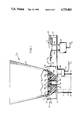
- FIG. 1 is a side elevation partly in section of the dispensing apparatus of the present invention showing the apparatus mounted above a can line.
- FIG. 2 is an exploded perspective view of the dispensing apparatus.
- FIG. 3 is a bottom plan view of the loading plate of the dispenser.
- FIG. 4 is a top plan view of the support block of the dispenser.
- FIG. 5 is a sectional view of the loading plate taken along line 5--5 of FIG. 2.
- the dispensing apparatus of the present invention is generally denoted by reference numeral 10.
- the dispenser may be used to dispense any granular or particulate material, it is particularly adapted for use in dispensing metered amounts of herbs and/or spices into cans in a high speed canning operation, such as in the commercial production of canned fruit or vegetable products.
- the dispensing apparatus 10 is adapted to be mounted above a can line on which metal cans 11 are carried on an endless conveyor 12 in a high speed canning operation, into which a measured volume of the particulate mix of herbs and/or spices is to be deposited.
- the dispenser 10 includes a rigid mounting plate 14 having an opening 15 therein which is positioned above the can line.
- a metering unit 16 which includes a reciprocating slide dispenser 35, is mounted on plate 14 for controlling the amount of particulate material dispensed in the cans.
- a hopper 18, in which the particulate material to be dispensed is stored, is mounted on the metering unit.
- the dispensing operation is effected automatically by means of a magnetic sensor 19 mounted adjacent the can line and an actuating valve 20 which controls the reciprocating movement of slide dispenser 35 through air cylinder 21.
- rigid mounting plate 14 is secured over the can line by any suitable means so that the bottom surface of plate 14 is maintained a short distance, i.e. on the order of about 1/4", above the can tops, and the mounting plate opening 15 is positioned over the center of the cans.
- plate 14 may be secured in position by a pair of mounting brackets 23 which are attached at their lower ends to the frame carrying the endless conveyor 12, and attached at their upper ends to the bottom surface of plate 14.
- a pair of upstanding support brackets 24 are mounted on the upper surface of plate 14 at one end thereof, and an air cylinder mounting pin 25 is secured to and extends between the support brackets.
- the metering unit generally referred to by reference numeral 16 includes a generally rectangular loading plate 26 having a flat planar bottom surface 27 which is mounted on the flat planar upper surface 28 of support block 29.
- Support block 29 has a centrally located discharge opening 30 which has a size and shape corresponding to a pair of longitudinally spaced loading openings 31 and 32 in loading plate 26, with the discharge opening 30 being positioned midway between openings 31 and 32 when the loading plate and support block are secured together.
- the support block 29 is fixed to the upper surface of the mounting plate 14 so that the discharge opening 30 is aligned with opening 15 in the mounting plate.
- a longitudinal channel 33 having a substantially flat bottom wall is provided in the upper surface 28 of support block 29, with the channel extending across the support block over discharge opening 30 and beneath loading openings 31 and 32 in the loading plate.
- the metering unit also includes an elongated, generally rectangular, flat slide dispenser bar 35 which is mounted for reciprocating movement in longitudinal channel 33.
- the dimensions of slide bar 35 are such that when the slide bar is positioned in channel 33, the upper surface of the slide bar is coplanar with the upper surface 28 of the support block, and the side walls of the slide bar are disposed in a mating manner with the side walls of the channel.
- the slide dispenser bar 35 is provided with a pair of metering openings 36 and 37 which are longitudinally spaced apart by a distance of one-half the distance between loading openings 31 and 32.
- each metering opening 36 or 37 in the slide bar defines the quantity or amount of particulate material to be dispensed into the cans.
- a stainless steel bushing 38 is fitted into each of the openings 30, 31, 32, 36 and 37 to prevent erosion at the edges of the opening due to reciprocatory movement of the slide bar.
- An air cylinder 21 is secured to one longitudinal end of the slide bar 35 by means of piston rod 41 to effect reciprocating movement of the slide bar in channel 33.
- Fluid pressure lines 39 and 40 are connected to the air cylinder to produce reciprocatory movement of piston rod 41.
- the piston rod undergoes a relatively short reciprocatory stroke in order to operate the slide bar, and is connected thereto by any suitable means.
- the end of the air cylinder remote from the slide bar is secured to mounting pin 25 which extends between support brackets 24.
- the particulate material to be dispensed is stored in hopper 18 which is generally rectangular in shape and which may be provided with a removable top cover (not shown).
- hopper 18 which is generally rectangular in shape and which may be provided with a removable top cover (not shown).
- the walls of the hopper taper downwardly, with the bottom ends of the hopper walls being secured to rectangular base plate 42 around the periphery of opening 43 in the base plate.
- the base plate is mounted on the upper surface of loading plate 27 so that hopper opening 43 extends over loading openings 31 and 32.
- the hopper is constructed of clear plastic material to permit observation of the level of particulate material in the hopper.
- any suitable material such as sheet metal may be used.
- the components of the metering unit preferably are molded from an inert plastic material, such as nylon molding powder, which has good dimensional stability, good abrasion resistance and good resistance to friction
- the metering unit is constructed to permit lubrication of the exterior surfaces of the slide bar during use.
- a pair of parallel longitudinal bores 44 and 45 are provided in loading plate 26, such as by drilling a small diameter tubular bore into the loading plate adjacent the loading openings 31 and 32.
- a plurality of spaced apertures 46 are provided in the bottom surface of the loading plate in that portion of the loading plate which is directly above slide bar 35.
- apertures 46 are formed in the bottom surface of loading plate 26 directly above the upper longitudinal edges 47 of the slide bar when the slide bar is disposed in channel 33 and the loading plate mounted on the support block.
- a pair of parallel, longitudinal bores 48 and 49 are provided in support block 29 below the bottom surface of the channel 33.
- a plurality of spaced apertures 50 which communicate with conduits 48 and 49, are provided in the channel 33, preferably at or near the longitudinal edges of the channel.
- a suitable lubricating fluid such as mineral oil, vegetable oil, and the like, is pumped from a supply tank (not shown) by compressed air through supply lines 51 and 52 into bores 44, 45, 48 and 49 and through apertures 46 and 50 to lubricate the exterior surfaces of slide bar 35 as it reciprocates in the channel.
- Supply lines 51 and 52 are secured to the loading plate and support block respectively by any suitable means, such as by screw threads provided on the enlarged sections 54 and 55 formed at the outer ends of the longitudinal bores.
- the dispensing apparatus also includes means for actuating the slide bar in response to the presence and line speed of cans passing underneath discharge opening 15.
- a conventional magnetic sensor 19 connected by line 57 to an electro-pneumatic control panel (not shown) is mounted on bracket 56 under mounting plate 14, adjacent the can line, a short distance upstream of the opening 15.
- the particulate material to be dispensed flows by gravity from the hopper into both loading openings 31 and 32 in the loading plate and fills metering opening 36 on the slide bar.
- the slide bar is moved to its extended position, due to actuation of the air cylinder in response to movement of a can under the dispenser, the movement of the slide bar is such that metering opening 36 is moved into alignment with discharge opening 30 and opening 15, and the particulate material in metering opening 36 is discharged into a can moving under opening 15.
- metering opening 37 is aligned with loading opening 32 in the loading plate so that the particulate material fills metering opening 37.
- the air cylinder is again actuated to move the slide bar to its retracted position in which metering opening 37 is moved into alignment with openings 30 and 15 and the particulate is discharged into the can.
- This cycle is repeated in response to every movement of a can on the can line being carried beneath the dispensing apparatus.
Landscapes
- Engineering & Computer Science (AREA)
- Mechanical Engineering (AREA)
- Quality & Reliability (AREA)
- Closures For Containers (AREA)
- Basic Packing Technique (AREA)
Abstract
Description
Claims (3)
Priority Applications (1)
| Application Number | Priority Date | Filing Date | Title |
|---|---|---|---|
| US06/877,615 US4733803A (en) | 1986-06-23 | 1986-06-23 | Particulate dispensing apparatus |
Applications Claiming Priority (1)
| Application Number | Priority Date | Filing Date | Title |
|---|---|---|---|
| US06/877,615 US4733803A (en) | 1986-06-23 | 1986-06-23 | Particulate dispensing apparatus |
Publications (1)
| Publication Number | Publication Date |
|---|---|
| US4733803A true US4733803A (en) | 1988-03-29 |
Family
ID=25370337
Family Applications (1)
| Application Number | Title | Priority Date | Filing Date |
|---|---|---|---|
| US06/877,615 Expired - Fee Related US4733803A (en) | 1986-06-23 | 1986-06-23 | Particulate dispensing apparatus |
Country Status (1)
| Country | Link |
|---|---|
| US (1) | US4733803A (en) |
Cited By (34)
| Publication number | Priority date | Publication date | Assignee | Title |
|---|---|---|---|---|
| FR2641520A1 (en) * | 1989-01-10 | 1990-07-13 | Ima Spa | APPARATUS FOR TEMPORARILY INTERRUPTING THE SUPPLY OF A FILLING MACHINE OF ALVEOLES OF A CONTINUOUS BELT |
| US5125781A (en) * | 1990-01-24 | 1992-06-30 | Recot, Inc. | Air lock for transfer of product into and out of vacuum or pressurized chamber |
| US5143126A (en) * | 1990-01-29 | 1992-09-01 | Ciba-Geigy Corporation | Vibratory process and apparatus for agglomerating and metering non-flowable powders |
| US5183507A (en) * | 1990-10-25 | 1993-02-02 | Scherer Welby J | Particulate material dispensing device |
| US5272961A (en) * | 1988-10-17 | 1993-12-28 | The R/M Trust Company | Apparatus for providing french fried potatoes |
| US5363984A (en) * | 1993-07-23 | 1994-11-15 | Gldrj Company | Display device having an article dispenser therein |
| US5441756A (en) * | 1990-09-17 | 1995-08-15 | Nestec S.A. | Process for distributing objects |
| US5498286A (en) * | 1993-03-26 | 1996-03-12 | Nestec S.A. | Apparatus for dosing a pumpable fluid |
| US5520100A (en) * | 1992-03-30 | 1996-05-28 | Nestec S.A. | Garniture applying apparatus |
| US5613626A (en) * | 1995-05-15 | 1997-03-25 | Firey; Joseph C. | Solids transfer mechanism |
| US5651401A (en) * | 1995-06-14 | 1997-07-29 | Sahara Natural Foods, Inc. | Apparatus for filling receptacles |
| US6145552A (en) * | 1999-09-16 | 2000-11-14 | Multi-Fill, Inc. | Particulate product following system and method |
| WO2002024140A2 (en) * | 2000-09-20 | 2002-03-28 | Solvay Pharmaceuticals Gmbh | Dosage dispenser for a free-flowing, pourable pulverulent or particulate substance |
| WO2002015839A3 (en) * | 2000-08-22 | 2002-08-01 | Advanced Inhalation Res Inc | System, method and apparatus for filling containers |
| WO2002081309A1 (en) * | 2001-04-04 | 2002-10-17 | Multi-Fill, Inc. | Pneumatically controlled volumetric pocket filler |
| US20030159751A1 (en) * | 2000-06-28 | 2003-08-28 | Jean-Pierre Chamba | Granular material dispenser |
| US20060117710A1 (en) * | 2004-12-06 | 2006-06-08 | Hsin-Tsai Wu | Filling device and method for making a mattress |
| WO2007017443A1 (en) * | 2005-08-05 | 2007-02-15 | Forschungszentrum Karlsruhe Gmbh | Apparatus for filling receptacles in parallel |
| US20070095425A1 (en) * | 2003-08-05 | 2007-05-03 | Yoshitugi Hashiba | Device and method for measuring hard granular objects |
| US20070210120A1 (en) * | 2005-08-31 | 2007-09-13 | The Coca-Cola Company | Coffee and tea dosing system |
| US20100320225A1 (en) * | 2005-08-31 | 2010-12-23 | The Coca-Cola Company | Coffee and Tea Dosing System |
| WO2011042207A1 (en) * | 2009-10-09 | 2011-04-14 | Philip Morris Products S.A. | Apparatus and method for forming and packaging molded tobacco pieces |
| US20110139812A1 (en) * | 2007-08-24 | 2011-06-16 | Allan Dagsland | Method For Dosing And Providing Powder In A Powder Provider, Such A Powder Provider Device And An Apparatus For Producing Packs |
| WO2013004756A1 (en) | 2011-07-06 | 2013-01-10 | Maschinenfabrik Leonhardt Gmbh | Variable metering system for heterogeneous, sensitive and non-pumpable foodstuffs having a low liquid portion |
| WO2015069750A1 (en) * | 2013-11-08 | 2015-05-14 | Intercontinental Great Brands Llc | System and method for dosing a popping chamber |
| CN104709483A (en) * | 2015-03-09 | 2015-06-17 | 青岛食安生物工程有限公司 | Semi-automatic powder filling machine |
| CN105599935A (en) * | 2016-02-16 | 2016-05-25 | 北京和利康源医疗科技有限公司 | Quantitative regulating device for granular preparations |
| CN106114924A (en) * | 2016-08-30 | 2016-11-16 | 湖南千山制药机械股份有限公司 | A kind of granular preparation packaging device |
| US10399712B2 (en) | 2013-12-26 | 2019-09-03 | Altria Client Services Llc | Slide measuring system for filling pouches and associated method |
| US10888108B2 (en) | 2015-07-30 | 2021-01-12 | Altria Client Services Llc | Slide measuring system for filling pouches and associated method |
| TWI728513B (en) * | 2019-10-18 | 2021-05-21 | 財團法人金屬工業研究發展中心 | Spherical granular food material granulating device |
| US11155371B2 (en) * | 2018-03-07 | 2021-10-26 | Ds-Technology Gmbh | Device for the dosed filling of a container with a filling material |
| US20220095701A1 (en) * | 2019-01-29 | 2022-03-31 | British American Tobacco (Investments) Limited | Method and Apparatus for Manufacturing a Consumable Unit for an Inhalation Device, and a Consumable Unit for an Inhalation Device |
| CN114701677A (en) * | 2022-05-11 | 2022-07-05 | 安徽和泰智能装备有限公司 | Granule measurement partial shipment module |
Citations (11)
| Publication number | Priority date | Publication date | Assignee | Title |
|---|---|---|---|---|
| US2033586A (en) * | 1933-09-12 | 1936-03-10 | Roads Construction Company Ltd | Gate operating device for automatic weighing machines |
| US2296081A (en) * | 1939-12-09 | 1942-09-15 | Aspin Frank Metcalf | Lubrication of rotary valves |
| US2315473A (en) * | 1940-03-30 | 1943-03-30 | Silex Co | Measuring dispenser |
| US2639837A (en) * | 1951-04-03 | 1953-05-26 | William A Stockdale | Coffee dispenser |
| US2951618A (en) * | 1956-10-19 | 1960-09-06 | Int Minerals & Chem Corp | Filling apparatus |
| US3314575A (en) * | 1965-02-23 | 1967-04-18 | Clayton Specialties Inc | Seed dispensing apparatus |
| US3623639A (en) * | 1970-07-21 | 1971-11-30 | Robert C Mcshirley | Powder-dispensing device |
| US4164244A (en) * | 1976-10-05 | 1979-08-14 | Sig Schweizerische Industrie-Gesellschaft | Apparatus for dosing bulk goods |
| US4295409A (en) * | 1979-04-20 | 1981-10-20 | Simpson Frank H | Shot and powder dispenser attachment |
| JPS57152366A (en) * | 1980-10-09 | 1982-09-20 | Kurosaki Refract Co Ltd | Method for performing prevention of damaging, repairing and other necessary treatments of plate slideway in sliding nozzle device |
| US4403715A (en) * | 1981-06-29 | 1983-09-13 | Ludovissie Anthony W | Device for dispensing a measured amount of a particulate material |
-
1986
- 1986-06-23 US US06/877,615 patent/US4733803A/en not_active Expired - Fee Related
Patent Citations (11)
| Publication number | Priority date | Publication date | Assignee | Title |
|---|---|---|---|---|
| US2033586A (en) * | 1933-09-12 | 1936-03-10 | Roads Construction Company Ltd | Gate operating device for automatic weighing machines |
| US2296081A (en) * | 1939-12-09 | 1942-09-15 | Aspin Frank Metcalf | Lubrication of rotary valves |
| US2315473A (en) * | 1940-03-30 | 1943-03-30 | Silex Co | Measuring dispenser |
| US2639837A (en) * | 1951-04-03 | 1953-05-26 | William A Stockdale | Coffee dispenser |
| US2951618A (en) * | 1956-10-19 | 1960-09-06 | Int Minerals & Chem Corp | Filling apparatus |
| US3314575A (en) * | 1965-02-23 | 1967-04-18 | Clayton Specialties Inc | Seed dispensing apparatus |
| US3623639A (en) * | 1970-07-21 | 1971-11-30 | Robert C Mcshirley | Powder-dispensing device |
| US4164244A (en) * | 1976-10-05 | 1979-08-14 | Sig Schweizerische Industrie-Gesellschaft | Apparatus for dosing bulk goods |
| US4295409A (en) * | 1979-04-20 | 1981-10-20 | Simpson Frank H | Shot and powder dispenser attachment |
| JPS57152366A (en) * | 1980-10-09 | 1982-09-20 | Kurosaki Refract Co Ltd | Method for performing prevention of damaging, repairing and other necessary treatments of plate slideway in sliding nozzle device |
| US4403715A (en) * | 1981-06-29 | 1983-09-13 | Ludovissie Anthony W | Device for dispensing a measured amount of a particulate material |
Cited By (56)
| Publication number | Priority date | Publication date | Assignee | Title |
|---|---|---|---|---|
| US5272961A (en) * | 1988-10-17 | 1993-12-28 | The R/M Trust Company | Apparatus for providing french fried potatoes |
| US5404796A (en) * | 1988-10-17 | 1995-04-11 | Campbell; Colin K. | Apparatus for providing french fried potatoes |
| FR2641520A1 (en) * | 1989-01-10 | 1990-07-13 | Ima Spa | APPARATUS FOR TEMPORARILY INTERRUPTING THE SUPPLY OF A FILLING MACHINE OF ALVEOLES OF A CONTINUOUS BELT |
| US5125781A (en) * | 1990-01-24 | 1992-06-30 | Recot, Inc. | Air lock for transfer of product into and out of vacuum or pressurized chamber |
| US5143126A (en) * | 1990-01-29 | 1992-09-01 | Ciba-Geigy Corporation | Vibratory process and apparatus for agglomerating and metering non-flowable powders |
| US5441756A (en) * | 1990-09-17 | 1995-08-15 | Nestec S.A. | Process for distributing objects |
| US5183507A (en) * | 1990-10-25 | 1993-02-02 | Scherer Welby J | Particulate material dispensing device |
| US5520100A (en) * | 1992-03-30 | 1996-05-28 | Nestec S.A. | Garniture applying apparatus |
| US5498286A (en) * | 1993-03-26 | 1996-03-12 | Nestec S.A. | Apparatus for dosing a pumpable fluid |
| AU669047B2 (en) * | 1993-03-26 | 1996-05-23 | Frisco-Findus Ag | Applicator |
| US5363984A (en) * | 1993-07-23 | 1994-11-15 | Gldrj Company | Display device having an article dispenser therein |
| US5613626A (en) * | 1995-05-15 | 1997-03-25 | Firey; Joseph C. | Solids transfer mechanism |
| US5651401A (en) * | 1995-06-14 | 1997-07-29 | Sahara Natural Foods, Inc. | Apparatus for filling receptacles |
| US6145552A (en) * | 1999-09-16 | 2000-11-14 | Multi-Fill, Inc. | Particulate product following system and method |
| US6748986B2 (en) * | 2000-06-28 | 2004-06-15 | Jean-Pierre Chamba | Granular material dispenser |
| US20030159751A1 (en) * | 2000-06-28 | 2003-08-28 | Jean-Pierre Chamba | Granular material dispenser |
| WO2002015839A3 (en) * | 2000-08-22 | 2002-08-01 | Advanced Inhalation Res Inc | System, method and apparatus for filling containers |
| AU2001283175B2 (en) * | 2000-08-22 | 2005-11-24 | Advanced Inhalation Research, Inc. | System, method and apparatus for filling containers |
| WO2002024140A2 (en) * | 2000-09-20 | 2002-03-28 | Solvay Pharmaceuticals Gmbh | Dosage dispenser for a free-flowing, pourable pulverulent or particulate substance |
| WO2002024140A3 (en) * | 2000-09-20 | 2002-09-12 | Solvay Pharm Gmbh | Dosage dispenser for a free-flowing, pourable pulverulent or particulate substance |
| US6619339B2 (en) | 2001-04-04 | 2003-09-16 | Multi-Fill, Inc. | Pneumatically controlled volumetric pocket filler |
| WO2002081309A1 (en) * | 2001-04-04 | 2002-10-17 | Multi-Fill, Inc. | Pneumatically controlled volumetric pocket filler |
| US20070095425A1 (en) * | 2003-08-05 | 2007-05-03 | Yoshitugi Hashiba | Device and method for measuring hard granular objects |
| US7849891B2 (en) * | 2003-08-05 | 2010-12-14 | Kureha Corporation | Device and method for measuring hard granular objects |
| US20060117710A1 (en) * | 2004-12-06 | 2006-06-08 | Hsin-Tsai Wu | Filling device and method for making a mattress |
| US7228675B2 (en) * | 2004-12-06 | 2007-06-12 | Hsin-Tsai Wu | Filling device and method for making a mattress |
| WO2007017443A1 (en) * | 2005-08-05 | 2007-02-15 | Forschungszentrum Karlsruhe Gmbh | Apparatus for filling receptacles in parallel |
| US7798376B2 (en) * | 2005-08-31 | 2010-09-21 | The Coca-Cola Company | Coffee and tea dosing system |
| US20100320225A1 (en) * | 2005-08-31 | 2010-12-23 | The Coca-Cola Company | Coffee and Tea Dosing System |
| US8016166B2 (en) | 2005-08-31 | 2011-09-13 | The Coca-Cola Company | Coffee and tea dosing system |
| US20070210120A1 (en) * | 2005-08-31 | 2007-09-13 | The Coca-Cola Company | Coffee and tea dosing system |
| US20110139812A1 (en) * | 2007-08-24 | 2011-06-16 | Allan Dagsland | Method For Dosing And Providing Powder In A Powder Provider, Such A Powder Provider Device And An Apparatus For Producing Packs |
| WO2011042207A1 (en) * | 2009-10-09 | 2011-04-14 | Philip Morris Products S.A. | Apparatus and method for forming and packaging molded tobacco pieces |
| US20110220523A1 (en) * | 2009-10-09 | 2011-09-15 | Philip Morris Usa Inc. | Apparatus and method for forming and packaging molded tobacco pieces |
| JP2013507110A (en) * | 2009-10-09 | 2013-03-04 | フィリップ・モーリス・プロダクツ・ソシエテ・アノニム | Apparatus and method for forming and packaging shaped tobacco parts |
| US8752558B2 (en) | 2009-10-09 | 2014-06-17 | Philip Morris Usa Inc. | Apparatus and method for forming and packaging molded tobacco pieces |
| US9345266B2 (en) | 2009-10-09 | 2016-05-24 | Philip Morris Usa Inc. | Apparatus and method for forming and packaging molded tobacco |
| US9169082B2 (en) | 2011-07-06 | 2015-10-27 | Maschinenfabrik Leonhardt Gmbh | Variable metering system for heterogeneous, sensitive and non-pumpable foodstuffs having a low liquid portion |
| WO2013004756A1 (en) | 2011-07-06 | 2013-01-10 | Maschinenfabrik Leonhardt Gmbh | Variable metering system for heterogeneous, sensitive and non-pumpable foodstuffs having a low liquid portion |
| DE102011051603A1 (en) | 2011-07-06 | 2013-01-10 | Maschinenfabrik Leonhardt Gmbh | Variable dosing system for heterogeneous, sensitive and non-pumpable foods with low liquid content |
| WO2015069750A1 (en) * | 2013-11-08 | 2015-05-14 | Intercontinental Great Brands Llc | System and method for dosing a popping chamber |
| CN105705043A (en) * | 2013-11-08 | 2016-06-22 | 洲际大品牌有限责任公司 | System and method for dosing a popping chamber |
| EP3065575A4 (en) * | 2013-11-08 | 2017-06-14 | Intercontinental Great Brands LLC | System and method for dosing a popping chamber |
| US11447277B2 (en) | 2013-12-26 | 2022-09-20 | Altria Client Services Llc | Slide measuring system for filling pouches and associated method |
| US10399712B2 (en) | 2013-12-26 | 2019-09-03 | Altria Client Services Llc | Slide measuring system for filling pouches and associated method |
| CN104709483A (en) * | 2015-03-09 | 2015-06-17 | 青岛食安生物工程有限公司 | Semi-automatic powder filling machine |
| US10888108B2 (en) | 2015-07-30 | 2021-01-12 | Altria Client Services Llc | Slide measuring system for filling pouches and associated method |
| US11744275B2 (en) | 2015-07-30 | 2023-09-05 | Altria Client Services Llc | Slide measuring system for filling pouches and associated method |
| CN105599935A (en) * | 2016-02-16 | 2016-05-25 | 北京和利康源医疗科技有限公司 | Quantitative regulating device for granular preparations |
| CN105599935B (en) * | 2016-02-16 | 2017-11-24 | 北京和利康源医疗科技有限公司 | Quantitative dispensing apparatus for granular preparation |
| CN106114924A (en) * | 2016-08-30 | 2016-11-16 | 湖南千山制药机械股份有限公司 | A kind of granular preparation packaging device |
| US11155371B2 (en) * | 2018-03-07 | 2021-10-26 | Ds-Technology Gmbh | Device for the dosed filling of a container with a filling material |
| US20220095701A1 (en) * | 2019-01-29 | 2022-03-31 | British American Tobacco (Investments) Limited | Method and Apparatus for Manufacturing a Consumable Unit for an Inhalation Device, and a Consumable Unit for an Inhalation Device |
| US11998063B2 (en) * | 2019-01-29 | 2024-06-04 | British American Tobacco (Investments) Limited | Method and apparatus for manufacturing a consumable unit for an inhalation device, and a consumable unit for an inhalation device |
| TWI728513B (en) * | 2019-10-18 | 2021-05-21 | 財團法人金屬工業研究發展中心 | Spherical granular food material granulating device |
| CN114701677A (en) * | 2022-05-11 | 2022-07-05 | 安徽和泰智能装备有限公司 | Granule measurement partial shipment module |
Similar Documents
| Publication | Publication Date | Title |
|---|---|---|
| US4733803A (en) | Particulate dispensing apparatus | |
| US4957226A (en) | Automatic food dispensing method, apparatus and utensil | |
| CA2396506C (en) | Material activator for material dispensing bin | |
| US3347287A (en) | Nozzle apparatus | |
| US20050173019A1 (en) | Apparatus for the simultaenous filling of precise amounts of viscous liquid material in a sanitary environment | |
| US4974755A (en) | Dispensing valve assembly and system | |
| US5035270A (en) | Automatic conveyorized container filler | |
| US4912681A (en) | System for creating a homogeneous admixture from liquid and relatively dry flowable material | |
| US5295523A (en) | Adjustable stroke multiple package filling apparatus | |
| US4026439A (en) | Precision fluid dispensing and mixing system | |
| US3207378A (en) | Metering pump assembly | |
| JP4598377B2 (en) | Multi-component weighing and dispensing device | |
| US5309958A (en) | Filling apparatus for viscous foods | |
| EP0334537B1 (en) | Bottom-up filler | |
| US5788127A (en) | Liquid dispensing valve | |
| RU2066444C1 (en) | Granulated and powder materials dozing apparatus | |
| US5067531A (en) | Bench top container filler | |
| ATE100398T1 (en) | ARRANGEMENT ON A PUMP UNIT. | |
| CN205819611U (en) | Coating automatic filling machine | |
| CA1080036A (en) | Adjustable liquid dispensing pump | |
| US20140110437A1 (en) | Bulk Feeding System and Method | |
| US3037674A (en) | Metering device | |
| US6024258A (en) | Material container that shuttles between supply and use sites | |
| US5016690A (en) | Dosing device on a filling plant, in particular for liquid and pasty products, and process for its operation | |
| JP4480227B2 (en) | Nozzle for fixed quantity filling |
Legal Events
| Date | Code | Title | Description |
|---|---|---|---|
| AS | Assignment |
Owner name: CARNATION COMPANY, 5045 WILSHIRE BOULEVARD, LOS AN Free format text: ASSIGNMENT OF ASSIGNORS INTEREST.;ASSIGNORS:SISSON, CHARLES W.;KERR, DUANE R.;MOSIER, RUSSELL H.;REEL/FRAME:004569/0712 Effective date: 19860613 |
|
| FPAY | Fee payment |
Year of fee payment: 4 |
|
| FPAY | Fee payment |
Year of fee payment: 8 |
|
| FEPP | Fee payment procedure |
Free format text: PAYOR NUMBER ASSIGNED (ORIGINAL EVENT CODE: ASPN); ENTITY STATUS OF PATENT OWNER: LARGE ENTITY |
|
| REMI | Maintenance fee reminder mailed | ||
| LAPS | Lapse for failure to pay maintenance fees | ||
| FP | Lapsed due to failure to pay maintenance fee |
Effective date: 20000329 |
|
| STCH | Information on status: patent discontinuation |
Free format text: PATENT EXPIRED DUE TO NONPAYMENT OF MAINTENANCE FEES UNDER 37 CFR 1.362 |