US4732085A - Smoke generation apparatus and process using magnetic field - Google Patents
Smoke generation apparatus and process using magnetic field Download PDFInfo
- Publication number
- US4732085A US4732085A US07/048,381 US4838187A US4732085A US 4732085 A US4732085 A US 4732085A US 4838187 A US4838187 A US 4838187A US 4732085 A US4732085 A US 4732085A
- Authority
- US
- United States
- Prior art keywords
- smoke
- magnetic field
- reaction chamber
- process according
- section
- Prior art date
- Legal status (The legal status is an assumption and is not a legal conclusion. Google has not performed a legal analysis and makes no representation as to the accuracy of the status listed.)
- Expired - Fee Related
Links
Images

Classifications
-
- F—MECHANICAL ENGINEERING; LIGHTING; HEATING; WEAPONS; BLASTING
- F42—AMMUNITION; BLASTING
- F42B—EXPLOSIVE CHARGES, e.g. FOR BLASTING, FIREWORKS, AMMUNITION
- F42B12/00—Projectiles, missiles or mines characterised by the warhead, the intended effect, or the material
- F42B12/02—Projectiles, missiles or mines characterised by the warhead, the intended effect, or the material characterised by the warhead or the intended effect
- F42B12/36—Projectiles, missiles or mines characterised by the warhead, the intended effect, or the material characterised by the warhead or the intended effect for dispensing materials; for producing chemical or physical reaction; for signalling ; for transmitting information
- F42B12/46—Projectiles, missiles or mines characterised by the warhead, the intended effect, or the material characterised by the warhead or the intended effect for dispensing materials; for producing chemical or physical reaction; for signalling ; for transmitting information for dispensing gases, vapours, powders or chemically-reactive substances
- F42B12/48—Projectiles, missiles or mines characterised by the warhead, the intended effect, or the material characterised by the warhead or the intended effect for dispensing materials; for producing chemical or physical reaction; for signalling ; for transmitting information for dispensing gases, vapours, powders or chemically-reactive substances smoke-producing, e.g. infrared clouds
-
- F—MECHANICAL ENGINEERING; LIGHTING; HEATING; WEAPONS; BLASTING
- F41—WEAPONS
- F41H—ARMOUR; ARMOURED TURRETS; ARMOURED OR ARMED VEHICLES; MEANS OF ATTACK OR DEFENCE, e.g. CAMOUFLAGE, IN GENERAL
- F41H9/00—Equipment for attack or defence by spreading flame, gas or smoke or leurres; Chemical warfare equipment
- F41H9/06—Apparatus for generating artificial fog or smoke screens
Definitions
- This invention relates to an improved smoke generator.
- it relates to a method and apparatus for producing dense smoke clouds for camouflage purposes.
- Pyrotechnic smoke compositions based on phosphorus, phosphorus-containing compositions, or HC smoke compositions, used in mortar smoke bodies, generate a fog consisting of finely divide acid droplets or hydroscopic salts, such as zinc chloride, (West German Patent Specification No. 1,185,510, West German Patent Specification No. 1,196,548 and West German Patent Specification No. 1,300,454).
- fog-clouds by the discharge of strongly hygroscopic acids such as chlorosulphonic acid, or of acid chlorides, such as phosphorus pentachloride or of liquids such as titanium tetrachloride, or of mixtures of the above-mentioned acids, acid chlorides or liquids in combination with amines, such as, for example, triethylamine as disclosed in the West German Unexamined Patent Application (Offenlegunqeschrift) No. 2,232,763. Furthermore, it is known to generate fog-clouds with fine droplets by dispersing oil or oil/water emulsions by means of compressed gas generators.
- While fire risk, risk of poisoning by the usually toxic fog, and only low scattering and absorption in the near infra-red range are generally inherent in pyrotechnic fogs, the acid fogs, acid chloride fogs, liquid fogs and two-component fogs, produced from the latter types with amines, possess, apart from only low scattering and absorption in the near infra-red range, the disadvantage of acute chemical attack, corrosion and toxicity.
- the oil fogs or oil/water emulsion fogs are completely permeable to the wave length range of the near infra-red light, (0.8 to 14 m).
- U.S. Pat. No. 4,210,555 discloses a method for producing smoke for military purposes which allegedly produces smoke which is cold, neutral, non-toxic as well as impermeable to infra-red instruments and other instruments used in military night vision techniques.
- the smoke is produced by using microfine powder, having a particle diameter of from 3 to 60 ⁇ m, being impenetrable to visible light and infra-red light of up to 14 ⁇ m wave length, and having a settling velocity of up to 5 cm/sec., which is dispersed in a very short time from a container by means of a propellant gas or explosive. Powders that can be used in practicing the invention of U.S. Pat. No.
- 4,210,555 are talc, kaolin, ammonium sulfate, ammonium phosphates, calcium carbonates, magnesium carbonates, sodium hydrogen carbonate, and other free-flowing powders, or powders that have been rendered flowable, which can form buoyant clouds upon being dispersed as by discharge of a compressed gas.
- Dispersion of the powder can be effected by known methods by means of propellant gas, e.g. CO 2 , N 2 or compressed air, inside or outside the receptacle containing the powder.
- propellant gas e.g. CO 2 , N 2 or compressed air
- Ejection of the powder is effected through an atomizerlike device having an ascending tube in the interior of the powder container, such tube ending in a suitable nozzle aperture for the fine division or dispersion of the powder into the surrounding atmosphere.
- separation between the release of compressed gas onto the powder and the efflux of the powder through the nozzle can be accomplished, for example, by means of an additional valve and/or a bursting-disc on the container. In this way, rapid and safe discharge of the fog-cloud is possible.
- U.S. Pat. No. 4,406,815 discloses an aerosol which allegedly reduces optical transmission by an attenuation technique which utilizes an aerosol of finely divided particles e.g. activated carbon black.
- the carbon black has a considerable "micro porosity,” that is a small scale porosity with holes having a size less than the optical wave lengths (i.e. ⁇ 0.1 ⁇ m).
- the carbon black particles have a very irregular configuration and an absorbing surface of up to 1200 m 2 /g. Eighty percent of the particles have diameters which are approximately equally distributed in the range between 1 to 9 ⁇ m.
- U.S. Pat. No. 4,538,151 discloses electro-magnetic wave absorbing material which comprises, inter alia, a mixture of ferrite and a high molecular weight synthetic resin, carbon black and short fibers of metal.
- the metal fibers preferably have a length (L) of 0.1-50 mm and a length (L) to diameter (D) ratio (L/D) of larger than 10.
- the quantity of metal fiber is larger than 3% by weight.
- the metal is a high conductivity metal such as Au, Ag, Cu, Cr, Zn, Ni, Fe or alloys thereof.
- the ferrite may be substituted by a ferromagnetic material such as iron, cobalt or nickel.
- the synthetic material can comprise the titanates of lead, barium and strontium as well as lead neobate and lead zirconate.
- U.S. Pat. No. 3,773,684 discloses a dipolar electrooptic composition and its method of preparation. Particles which have a dipole moment or exhibit a dipole moment in a magnetic field are suspended in a fluid medium. Illustrative of the dipole particles are herapathite particles and metals. The invention is directed primarily toward reversible effects produced by changing current polarity on fluids having suspended therein particles having a dipole moment.
- smoke useful for camouflage purposes can be prepared by suspending material in a fluid medium, and vaporizing the medium using a heat source while mixing the fluid with an inert carrier gas. Both the suspended particles and the fluid carrier medium which becomes an aerosol, contribute to the "smoke". It is also known to form smoke with suspended particles by decomposing a liquid feedstock to form the particles. Proper selection of the particles, from which radar, infra-red or other electromagnetic waves are absorbed or scattered, results in a smoke opaque to both visible light and other electromagnetic radiation.
- the disadvantage of the prior art method is that there is a requirement for a large volume source of inert gas. Additionally, a heat source is required to produce steam which is utilized to vaporize the fluid carrier medium in a heat exchanger.
- An important aspect of the prior art generation process is the use of a magnetic field which aligns the particles of the feed and causes "growth" of the particles to a size to result in optimum obscurant effect of the smoke in the electromagnetic wave range of interest.
- the smoke produced must be essentially near ambient temperature so that it will not rise as a result of thermal convection.
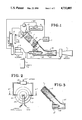
- FIG. 1 is a schematic of an improved smoke generator
- FIG. 2 is a plan view of the reactor head with nozzles
- FIG. 3 is a cross section of the reaction zone and air injector
- FIG. 4 is a cross section of part of the reactor head along line 4';4' in FIG. 2;
- FIG. 5 is a cross sectional view of the simplified smoke generator.
- a solid propellant can be used as the source of inert gas in a smoke generation process.
- the hot inert gases serve to vaporize the feedstock utilized into which are dispersed smoke creating particles.
- a liquid feedstock is decomposed to form solid particles.
- a magnetic field is utilized as in the prior art method to align the magnetically polarizable particles and to cause controlled particle "growth" into filaments.
- This invention relates to smoke generators.
- smoke generators suitable for military use in camouflage operations.
- a solid fuel propellant is utilized to generate a hot substantially inert carrier gas.
- the carrier gas comprises N 2 , CO 2 , CO, NH 3 , H 2 and minimal amounts of H 2 O, as well as insignificant amounts of other components.
- the gas contains no oxygen.
- a feedstock which comprises a fluid carrier medium is injected into the hot gas stream. It will be appreciated that a fluid carrier while preferred is not essential where other smoke generating particles are injected directly into the inert gas stream.
- the term "substantially inert" when used with respect to the carrier gas means that the gas is substantially free of oxygen and water and that other components are inert with respect to the fluid carrier medium, if used, and to the other smoke generating particles which are suspended in the fluid carrier or injected directly into the inert carrier gas.
- the invention is described in detail with respect to a system utilizing a liquid feedstock which decomposes to form solid particles. However it can also be utilized with a fluid carrier medium into which other smoke generating particles are suspended. It will be appreciated by those skilled in the art having access to this disclosure that smoke generating particles can be atomized directly into the inert carrier gas without utilizing a fluid carrier medium.
- feedstock means a fluid which decomposes into smoke forming particles or a fluid medium having dispersed therein other smoke forming materials.
- the prior art smoke generating feedstocks are suitable for use in the practice of this invention.
- One type of feedstock can comprise microfine powders having a particle diameter of about 1 to about 60 ⁇ m, preferably about 2 to about 50 ⁇ m more preferably about 3 to about 40 ⁇ m.
- Suitable powders useful in smoke generation include talc, kaolin, ammonium sulfate, ammonium phosphate, calcium carbonates, sodium hydrogen carbonate as well as metal powders or metal oxide powders.
- Illustrative of the metals which can be utilized are iron, copper, aluminum, chromium, ferrous alloys, etc. The oxides of these metals in powder form are similarly useful in the smoke production of this invention.
- the powders can be used in the neat form or can be dispersed in a fluid carrier.
- suitable fluid carriers are organic solvents such as hexane, benzene and cyclohexane; oils, including light weight solvent oils of the type produced in isooctane processes and used in dry cleaning processes, e.g. Exxon's ISOPAR L or M, and low viscosity machine oils.
- the oils can be optionally emulsified in water.
- liquid feedstock is one which decomposes to form particles.
- Illustrative of this latter type of feedstock suitable for use in the practice of this invention is GAF-SX1 manufactured by GAF Chemicals Corporation, Wayne, N.J.
- solid fuel propellants suitable for use in the practice of this invention are castable ammonium nitrate propellants such as Olin's OMAX 600.
- a solid propellant housed in solid propellant canister, 8, is burned.
- the gases produced are fed via transfer line, 8A to the carrier gas manifold, 12 and introduced into the reaction chamber, 1 through the inert gas inlet, 3A in the reaction chamber head, 3.
- the feedstock is fed from the feedstock container, 13 to the atomizing nozzles, 3B by using a source of pressure, 10, e.g. nitrogen gas to pressurize feedstock container, 13.
- An electric generator, 7 energizes the electromagnets, 2 which surround the reaction chamber, 1.
- the flux lines of the electro magnets are parallel to the direction of flow of the gases in the reaction chamber. Particulate matter in the feedstock or that resulting from the decomposition of liquid feedstock, exhibit magnetic polarized behavior in the magnetic field, and as a consequence, are aligned with the flux lines of the magnetic field. The particles line up to form small rods while in the flux field. It will be apparent to those skilled in the art who have access to this disclosure that the strength of the flux field and the time period during which the feedstock particles are within the magnetic field of the reactor must be controlled to avoid gross agglomeration of the particles as distinguished from a controlled agglomeration which results in desirable particles filament growth.
- the particles generated in the flux field should have a length of 0.5 micrometers up to approximately 5 millimeters and the diameter of each particle is no less than 0.01 micrometers to no more than 25 micrometers.
- the flux field must have a strength of at least a threshold value of at least 200 gauss, so as to orient the smoke particles and cause controlled growth.
- a flux field of about 300 to about 500 gauss is preferred.
- the smoke particles should be in the magnetic field for a time effective to accomplish the degree of particle filament growth desired.
- Air is introduced into the air inlet nozzle from a blower, 6 which is powered by the electric generator, 7.
- the air introduced to the air inlet nozzle of the second stage air mover, 5, entrains a large volume of ambient air and serves both to cool the smoke and spread out the filaments in the smoke.
- the smoke In order that the smoke not be dispersed into the atmosphere and lost by thermal convection it must be substantially at ambient temperature. Where the smoke leaving the reaction chamber has not been sufficiently cooled by the air introduced in the ejector, sufficient liquid nitrogen or other cooling material is added for the purpose of cooling. Such material also gives a head of pressure so that it atomizes.
- the nitrogen can be introduced into the air nozzle, 4A from a liquid nitrogen tank, 9 to cool the smoke to substantially ambient temperature.
- the nitrogen flow rate is a function of the gas temperature exiting the reaction chamber and the flow rate of the gas. For different feed stocks the nitrogen flow rate is readily determined by monitoring the temperature of the smoke exiting the ejector and adjusting the nitrogen flow rate accordingly. Increased flow rate will result in lower smoke exit temperatures.
- the gas exiting the reaction chamber is introduced into the ejector at an oblique angle, ⁇ .
- ⁇ is an oblique angle of about 25° to about 90°; more preferably about 30° to about 50°, e.g. 45°.
- filament growth in the reaction chamber can also be controlled by using a fixed exposure time and varying the field strength with time.
- Magnetic fields which are interrupted fields, fluctuating fields or moving fields can be utilized.
- An interrupted field is produced by turning the power to the electromagnet on and off so that the excitation of the field is interrupted at a controlled frequency.
- a fluctuating field is generated by varying the excitation voltage over a range from some minimum value sufficient to generate a field strength of at least 200 gauss to some preselected maximum voltage.
- a moving magnetic field can be generated by dividing the electromagnet into a multiplicity of sections.
- the excitation current is turned on in a first section for a preselected time interval.
- the excitation voltage to a second following section is turned on. In this way the field will be cause to move along the reaction chamber axially in the same direction of the gas flow.
- the field is caused to move along the reaction chamber at the same speed as the smoke particle flow.
- the magnetic field is both moving and fluctuating. This is accomplished by having the voltage is subsequent sections fluctuating out of phase with one another.
- the voltage in the first, third and each subsequent odd numbered section can be in phase with one another, while the voltage in the second section is out of with the voltage in the first section, but in phase with the voltage in each subsequent even numbered section.
- the fluctuating voltage can be controlled so that when the voltage in the first section is at about one-half of its maximum value the voltage in the second section is at its minimum value, and when the voltage in the first section has reached its maximum value the voltage in the third section is at its minimum value. This sequence can be repeated down the length of the reaction chamber.
- a solid propellant canister 1, houses a suitable solid propellant, 10, which when ignited delivers inert gas through orifice, 9, into a combustion chamber, 5.
- Feedstock is fed from a feedstock container, 2, using a pressure source, 4, to pump feedstock through delivery tube, 3, into nozzle, 7, which atomizes the feedstock.
- Liquid nitrogen is fed into the combustion chamber to cool the smoke generated. The nitrogen and atomized particles move through an exhaust nozzle, 8, which is within a magnetic field generated by electromagnet, 6, powered by an external power source (not shown).
- cooling medium is indicated as nitrogen in the description, as is apparent, any suitable cooling system can be used.
- Typical carbon dioxide is a suitable material.
- venturi any type of apparatus can be utilized which accelerates the flow to produce the venturi effect.
Abstract
Description
Claims (32)
Priority Applications (6)
| Application Number | Priority Date | Filing Date | Title |
|---|---|---|---|
| US07/048,381 US4732085A (en) | 1987-05-11 | 1987-05-11 | Smoke generation apparatus and process using magnetic field |
| KR1019890700981A KR890701981A (en) | 1987-05-11 | 1988-04-06 | Electric Disc Brake |
| EP19880904775 EP0313635A4 (en) | 1987-05-11 | 1988-04-11 | Smoke generation apparatus and process. |
| PCT/US1988/001173 WO1988008954A1 (en) | 1987-05-11 | 1988-04-11 | Smoke generation apparatus and process |
| JP63504233A JPH01503401A (en) | 1987-05-11 | 1988-04-11 | Smoke generating device and method |
| IL86235A IL86235A0 (en) | 1987-05-11 | 1988-05-01 | Smoke generation apparatus and process using magnetic field |
Applications Claiming Priority (1)
| Application Number | Priority Date | Filing Date | Title |
|---|---|---|---|
| US07/048,381 US4732085A (en) | 1987-05-11 | 1987-05-11 | Smoke generation apparatus and process using magnetic field |
Publications (1)
| Publication Number | Publication Date |
|---|---|
| US4732085A true US4732085A (en) | 1988-03-22 |
Family
ID=21954272
Family Applications (1)
| Application Number | Title | Priority Date | Filing Date |
|---|---|---|---|
| US07/048,381 Expired - Fee Related US4732085A (en) | 1987-05-11 | 1987-05-11 | Smoke generation apparatus and process using magnetic field |
Country Status (6)
| Country | Link |
|---|---|
| US (1) | US4732085A (en) |
| EP (1) | EP0313635A4 (en) |
| JP (1) | JPH01503401A (en) |
| KR (1) | KR890701981A (en) |
| IL (1) | IL86235A0 (en) |
| WO (1) | WO1988008954A1 (en) |
Cited By (10)
| Publication number | Priority date | Publication date | Assignee | Title |
|---|---|---|---|---|
| US4998479A (en) * | 1988-06-15 | 1991-03-12 | Perham William J | Smoke generating device with rechargable cartridge |
| US5168544A (en) * | 1991-05-31 | 1992-12-01 | Aai Corporation | Method and apparatus for controllably generating simulated smoke |
| US5682010A (en) * | 1996-12-04 | 1997-10-28 | The United States Of America As Represented By The Secretary Of The Army | Method for creating a one way visible screening smoke |
| US5870524A (en) * | 1997-01-24 | 1999-02-09 | Swiatosz; Edmund | Smoke generator method and apparatus |
| US5988039A (en) * | 1995-05-10 | 1999-11-23 | Lockheed Martin Tactical Sytems U.K. Limited | Weapon simulator |
| US20050260138A1 (en) * | 2004-05-21 | 2005-11-24 | Virgil Flanigan | Producton and use of a gaseous vapor disinfectant |
| GB2431124A (en) * | 2005-10-15 | 2007-04-18 | John Alan Coller | Amplifying the flow in a generator of smoke or fog |
| US20090321534A1 (en) * | 2005-12-02 | 2009-12-31 | Nfd, Llc | Aerosol or gaseous decontaminant generator and application thereof |
| US20100294157A1 (en) * | 2008-05-09 | 2010-11-25 | Dindl Frank J | Self Contained Non Toxic Obscurant Grenade And Self-Contained Aerosol Dispersing Grenade |
| CN114459294A (en) * | 2021-12-29 | 2022-05-10 | 宜昌测试技术研究所 | Airflow dispersion type cold smoke discharging device |
Families Citing this family (3)
| Publication number | Priority date | Publication date | Assignee | Title |
|---|---|---|---|---|
| FR2669625B1 (en) * | 1990-11-22 | 1994-06-03 | Giat Ind Sa | EFFECTIVE MASKING MATERIAL IN THE INFRARED FIELD. |
| KR100351486B1 (en) * | 1998-08-21 | 2002-10-19 | 주식회사 만도 | Electric brake device of a car |
| US6421502B1 (en) | 2000-12-07 | 2002-07-16 | Quikpoint, Inc. | Smoke generator and toy smoke-ring gun using same |
Citations (5)
| Publication number | Priority date | Publication date | Assignee | Title |
|---|---|---|---|---|
| US4377113A (en) * | 1981-02-09 | 1983-03-22 | Florence John R | Rocket firing system |
| US4406815A (en) * | 1978-03-31 | 1983-09-27 | Arnold Magnusson | Transmission reducing aerosol |
| US4446794A (en) * | 1979-04-02 | 1984-05-08 | Aktiebolaget Bofors | Practice shell particularly useful for training purposes |
| DE3521184A1 (en) * | 1984-04-03 | 1986-12-18 | Pyrotechnische Fabrik F. Feistel GmbH + Co KG, 6719 Göllheim | Ejected smoke generator |
| US4700628A (en) * | 1985-04-30 | 1987-10-20 | A/S Raufoss Ammunisjonsfabrikker A/S | Smoke grenade |
Family Cites Families (6)
| Publication number | Priority date | Publication date | Assignee | Title |
|---|---|---|---|---|
| FR816573A (en) * | 1936-12-17 | 1937-08-11 | Improvements to remotely controlled smoke generating systems | |
| US2408429A (en) * | 1942-05-06 | 1946-10-01 | Alonzo C Patterson | Smoke screen composition and the method of developing smoke screens therefrom |
| GB1017820A (en) * | 1954-02-15 | 1966-01-19 | Lucas Industries Ltd | Smoke producing apparatus |
| FR1335848A (en) * | 1962-10-10 | 1963-08-23 | Method of accelerating chemical reactions by means of a magnetic flux | |
| US3607780A (en) * | 1968-10-28 | 1971-09-21 | Forrest G Scott | Nonlethal thermal-aerosol generator weapon |
| US4538151A (en) * | 1982-03-31 | 1985-08-27 | Nippon Electric Co., Ltd. | Electro-magnetic wave absorbing material |
-
1987
- 1987-05-11 US US07/048,381 patent/US4732085A/en not_active Expired - Fee Related
-
1988
- 1988-04-06 KR KR1019890700981A patent/KR890701981A/en not_active Application Discontinuation
- 1988-04-11 JP JP63504233A patent/JPH01503401A/en active Pending
- 1988-04-11 EP EP19880904775 patent/EP0313635A4/en not_active Withdrawn
- 1988-04-11 WO PCT/US1988/001173 patent/WO1988008954A1/en not_active Application Discontinuation
- 1988-05-01 IL IL86235A patent/IL86235A0/en unknown
Patent Citations (5)
| Publication number | Priority date | Publication date | Assignee | Title |
|---|---|---|---|---|
| US4406815A (en) * | 1978-03-31 | 1983-09-27 | Arnold Magnusson | Transmission reducing aerosol |
| US4446794A (en) * | 1979-04-02 | 1984-05-08 | Aktiebolaget Bofors | Practice shell particularly useful for training purposes |
| US4377113A (en) * | 1981-02-09 | 1983-03-22 | Florence John R | Rocket firing system |
| DE3521184A1 (en) * | 1984-04-03 | 1986-12-18 | Pyrotechnische Fabrik F. Feistel GmbH + Co KG, 6719 Göllheim | Ejected smoke generator |
| US4700628A (en) * | 1985-04-30 | 1987-10-20 | A/S Raufoss Ammunisjonsfabrikker A/S | Smoke grenade |
Cited By (14)
| Publication number | Priority date | Publication date | Assignee | Title |
|---|---|---|---|---|
| US4998479A (en) * | 1988-06-15 | 1991-03-12 | Perham William J | Smoke generating device with rechargable cartridge |
| US5168544A (en) * | 1991-05-31 | 1992-12-01 | Aai Corporation | Method and apparatus for controllably generating simulated smoke |
| WO1992021916A1 (en) * | 1991-05-31 | 1992-12-10 | Aai Corporation | Method and apparatus for controllably generating simulated smoke |
| US5988039A (en) * | 1995-05-10 | 1999-11-23 | Lockheed Martin Tactical Sytems U.K. Limited | Weapon simulator |
| US5682010A (en) * | 1996-12-04 | 1997-10-28 | The United States Of America As Represented By The Secretary Of The Army | Method for creating a one way visible screening smoke |
| US5870524A (en) * | 1997-01-24 | 1999-02-09 | Swiatosz; Edmund | Smoke generator method and apparatus |
| US20050260138A1 (en) * | 2004-05-21 | 2005-11-24 | Virgil Flanigan | Producton and use of a gaseous vapor disinfectant |
| US20090298935A1 (en) * | 2004-05-21 | 2009-12-03 | Virgil Flanigan | Production And Use Of A Gaseous Vapor Disinfectant |
| GB2431124A (en) * | 2005-10-15 | 2007-04-18 | John Alan Coller | Amplifying the flow in a generator of smoke or fog |
| US20090321534A1 (en) * | 2005-12-02 | 2009-12-31 | Nfd, Llc | Aerosol or gaseous decontaminant generator and application thereof |
| US20100294157A1 (en) * | 2008-05-09 | 2010-11-25 | Dindl Frank J | Self Contained Non Toxic Obscurant Grenade And Self-Contained Aerosol Dispersing Grenade |
| US7946228B2 (en) * | 2008-05-09 | 2011-05-24 | Wendy Gainsborough, legal representative | Self contained non toxic obscurant grenade and self-contained aerosol dispersing grenade |
| CN114459294A (en) * | 2021-12-29 | 2022-05-10 | 宜昌测试技术研究所 | Airflow dispersion type cold smoke discharging device |
| CN114459294B (en) * | 2021-12-29 | 2023-07-14 | 宜昌测试技术研究所 | Airflow dispersion type cold smoke applying device |
Also Published As
| Publication number | Publication date |
|---|---|
| IL86235A0 (en) | 1988-11-15 |
| KR890701981A (en) | 1989-12-22 |
| JPH01503401A (en) | 1989-11-16 |
| WO1988008954A1 (en) | 1988-11-17 |
| EP0313635A1 (en) | 1989-05-03 |
| EP0313635A4 (en) | 1989-09-19 |
Similar Documents
| Publication | Publication Date | Title |
|---|---|---|
| US4732085A (en) | Smoke generation apparatus and process using magnetic field | |
| US5390864A (en) | Apparatus for forming fine particles | |
| DE60220508T2 (en) | FIRE AND EXPLOSION SUPPRESSION | |
| US4210555A (en) | Process for the generation of dense clouds for camouflage purposes | |
| EP0804945A2 (en) | Method and device for extinguishing fires in an enclosed space | |
| US2944029A (en) | Aerosolization process | |
| CA1137741A (en) | Transmission attenuating aerosol | |
| US3227642A (en) | Fluid processing apparatus and method | |
| US3607780A (en) | Nonlethal thermal-aerosol generator weapon | |
| EP0471742A1 (en) | Arrangement in a smoke camouflage system. | |
| US3975292A (en) | Method of screening infra-red radiation | |
| DE19649892A1 (en) | Infra-red emitting flare useful for igniting combustible flakes comprises rupturable container in which combustible flakes comprising fibrous, carbon containing substrate are disposed; and ignition unit | |
| CA2035441A1 (en) | Method of atomizing a liquid and apparatus for implementing the method | |
| US4129252A (en) | Method and apparatus for production of seeding materials | |
| Yuen et al. | Heat transfer characteristics of a gas-particle mixture under direct radiant heating | |
| US3899129A (en) | Apparatus for generating ice nuclei smoke particles for weather modification | |
| US4759500A (en) | Process for chilling stream of gas-suspended particles | |
| US2633455A (en) | Smoke generator | |
| US2882239A (en) | Aerosol dispersion apparatus | |
| CA1265345A (en) | Process and device for chilling stream of gas- suspended particles | |
| US2603607A (en) | Smoke generating device | |
| DE2911639A1 (en) | Heat-radiation emitting aerosol cloud generation - providing decoy using fluid supplied to several vaporisation jets | |
| WO1991008321A1 (en) | Method for gas-plasma spraying of metal coatings | |
| USH769H (en) | Method of forming a safe visual smoke screen | |
| USH775H (en) | Method of assembly of compacted powder and explosive charge for effective dissemination |
Legal Events
| Date | Code | Title | Description |
|---|---|---|---|
| AS | Assignment |
Owner name: GAF CORPORATION, 1361 ALPS RD., WAYNE, NJ 07470 A Free format text: ASSIGNMENT OF ASSIGNORS INTEREST.;ASSIGNORS:GERSHENSON, MOSHE;MOSKOWITZ, MARK L.;REEL/FRAME:004764/0828 Effective date: 19870708 Owner name: GAF CORPORATION,NEW JERSEY Free format text: ASSIGNMENT OF ASSIGNORS INTEREST;ASSIGNORS:GERSHENSON, MOSHE;MOSKOWITZ, MARK L.;REEL/FRAME:004764/0828 Effective date: 19870708 |
|
| FEPP | Fee payment procedure |
Free format text: PAYOR NUMBER ASSIGNED (ORIGINAL EVENT CODE: ASPN); ENTITY STATUS OF PATENT OWNER: LARGE ENTITY |
|
| AS | Assignment |
Owner name: CHASE MANHATTAN BANK, THE NATIONAL ASSOCIATION Free format text: SECURITY INTEREST;ASSIGNOR:DORSET INC. A CORP OF DELAWARE;REEL/FRAME:005122/0370 Effective date: 19890329 |
|
| AS | Assignment |
Owner name: GAF CHEMICALS CORPORATION Free format text: CHANGE OF NAME;ASSIGNOR:DORSET INC.;REEL/FRAME:005251/0071 Effective date: 19890411 |
|
| AS | Assignment |
Owner name: DORSET INC., A DE CORP. Free format text: CHANGE OF NAME;ASSIGNOR:GAF CORPORATION, A DE CORP.;REEL/FRAME:005250/0940 Effective date: 19890410 |
|
| AS | Assignment |
Owner name: CHASE MANHATTAN BANK (NATIONAL ASSOCIATION), THE Free format text: SECURITY INTEREST;ASSIGNOR:GAF CHEMICALS CORPORATION, A CORP. OF DE;REEL/FRAME:005604/0020 Effective date: 19900917 |
|
| FPAY | Fee payment |
Year of fee payment: 4 |
|
| AS | Assignment |
Owner name: ISP INVESTMENTS INC. Free format text: CHANGE OF NAME;ASSIGNOR:ISP 3 CORP.;REEL/FRAME:005949/0051 Effective date: 19910508 Owner name: ISP 3 CORP Free format text: ASSIGNMENT OF ASSIGNORS INTEREST.;ASSIGNOR:GAF CHEMICALS CORPORATION;REEL/FRAME:005949/0001 Effective date: 19910508 |
|
| AS | Assignment |
Owner name: GAF CHEMICALS CORPORATION Free format text: RELEASED BY SECURED PARTY;ASSIGNOR:CHASE MANHATTAN BANK, THE (NATIONAL ASSOCIATION);REEL/FRAME:006243/0208 Effective date: 19920804 Owner name: SUTTON LABORATORIES, INC. Free format text: RELEASED BY SECURED PARTY;ASSIGNOR:CHASE MANHATTAN BANK, THE (NATIONAL ASSOCIATION);REEL/FRAME:006243/0208 Effective date: 19920804 Owner name: GAF BUILDING MATERIALS CORPORATION Free format text: RELEASED BY SECURED PARTY;ASSIGNOR:CHASE MANHATTAN BANK, THE (NATIONAL ASSOCIATION);REEL/FRAME:006243/0208 Effective date: 19920804 |
|
| FPAY | Fee payment |
Year of fee payment: 8 |
|
| REMI | Maintenance fee reminder mailed | ||
| REMI | Maintenance fee reminder mailed | ||
| LAPS | Lapse for failure to pay maintenance fees | ||
| FP | Lapsed due to failure to pay maintenance fee |
Effective date: 20000322 |
|
| STCH | Information on status: patent discontinuation |
Free format text: PATENT EXPIRED DUE TO NONPAYMENT OF MAINTENANCE FEES UNDER 37 CFR 1.362 |