US4731523A - Bill receiving device - Google Patents
Bill receiving device Download PDFInfo
- Publication number
- US4731523A US4731523A US06/892,496 US89249686A US4731523A US 4731523 A US4731523 A US 4731523A US 89249686 A US89249686 A US 89249686A US 4731523 A US4731523 A US 4731523A
- Authority
- US
- United States
- Prior art keywords
- bill
- receiving chamber
- pushing member
- bills
- receiving
- Prior art date
- Legal status (The legal status is an assumption and is not a legal conclusion. Google has not performed a legal analysis and makes no representation as to the accuracy of the status listed.)
- Expired - Lifetime
Links
- 230000007246 mechanism Effects 0.000 claims abstract description 23
- 230000000694 effects Effects 0.000 claims description 4
- 238000012545 processing Methods 0.000 description 10
- 230000008859 change Effects 0.000 description 8
- 238000010276 construction Methods 0.000 description 8
- 238000001514 detection method Methods 0.000 description 6
- 238000003780 insertion Methods 0.000 description 3
- 230000037431 insertion Effects 0.000 description 3
- 238000000034 method Methods 0.000 description 2
- 230000009467 reduction Effects 0.000 description 2
- 230000004044 response Effects 0.000 description 2
- 230000007547 defect Effects 0.000 description 1
- 230000014759 maintenance of location Effects 0.000 description 1
- 230000008569 process Effects 0.000 description 1
- 230000000717 retained effect Effects 0.000 description 1
Images


Classifications
-
- G—PHYSICS
- G07—CHECKING-DEVICES
- G07D—HANDLING OF COINS OR VALUABLE PAPERS, e.g. TESTING, SORTING BY DENOMINATIONS, COUNTING, DISPENSING, CHANGING OR DEPOSITING
- G07D3/00—Sorting a mixed bulk of coins into denominations
-
- B—PERFORMING OPERATIONS; TRANSPORTING
- B65—CONVEYING; PACKING; STORING; HANDLING THIN OR FILAMENTARY MATERIAL
- B65H—HANDLING THIN OR FILAMENTARY MATERIAL, e.g. SHEETS, WEBS, CABLES
- B65H29/00—Delivering or advancing articles from machines; Advancing articles to or into piles
- B65H29/38—Delivering or advancing articles from machines; Advancing articles to or into piles by movable piling or advancing arms, frames, plates, or like members with which the articles are maintained in face contact
- B65H29/46—Members reciprocated in rectilinear path
-
- G—PHYSICS
- G07—CHECKING-DEVICES
- G07D—HANDLING OF COINS OR VALUABLE PAPERS, e.g. TESTING, SORTING BY DENOMINATIONS, COUNTING, DISPENSING, CHANGING OR DEPOSITING
- G07D11/00—Devices accepting coins; Devices accepting, dispensing, sorting or counting valuable papers
- G07D11/10—Mechanical details
- G07D11/12—Containers for valuable papers
- G07D11/13—Containers for valuable papers with internal means for handling valuable papers
Definitions
- This invention relates to a bill receiving device in a bill device used for a vending machine or a money exchanger.
- a bill device used for a vending machine or a money exchanger consists generally of a bill discrimination device for discriminating whether a deposited bill is a true bill or a false one as well as denomination thereof and a bill receiving device for receiving a bill which has been accepted as a true bill by the bill discrimination device.
- Known in the art are various bill receiving devices.
- a bill receiving device capable of paying out a once received bill per se is known.
- Also known is a bill receiving device capable of stacking bills of two different denominations separately.
- These prior art bill receiving devices having special functions have a common defect that they are obliged to adopt a relatively large-scale construction.
- a largescale bill payout mechanism is required.
- the bill receiving device capable of stacking bills of two different denominations separately separate receiving structures and mechanisms are required for the respective denominations.
- an object of the present invention to provide a bill receiving device capable of dividing bills into two kinds and receiving the divided bills separately with a very compact construction and, besides, with respect to a bill of at least one specific denomination, capable of paying it out as required by means of a payout mechanism of an extremely simple construction.
- the bill receiving device is characterized in that it comprises a bill passage, conveying meand for cnveying a bill delivered to said bill passage to a predetermined position for receiving it, first and second bill receiving chambers formed on both sides of said bill passage, at least said first bill receiving chamber having a bill outlet, a bill pushing member being capable of moving in a reciprocating motion across said first and second bill receiving chambers through said bill passage and, when the bill located at the predetermined position in said bill passage is to be received in said first bill receiving chamber, effects receiving of the bill by pushing it with a first surface of said bill pushing member while moving from said second bill receiving chamber towards said first bill receiving chamber and, when the bill is to be recieved in said second bill receiving chamber, effects receiving of the bill by pushing it with a second surface of said bill pushing member which is opposite to said first surface while moving from said first bill receiving chamber towards said second bill receiving chamber, and a bill payout mechanism provided in said bill pushing member and having a bill conveying member exposed on at least
- the two bill receiving chambers can be constructed of an integral bill receiving structure so that an extremely compact construction can be adopted. Further, by adopting the arrangement that the bill pushing member which performs the pushing operation for receiving bills in the bill receiving chambers reciprocates between the two bill receiving chambers through the centrally located bill passage, the bill pushing member can be used commonly for receiving bills in the respective bill receiving chambers whereby necessity for providing a bill receiving mechanism in each of the bill receiving chambers is obviated so that the structure can be simplified. Further, the provision of the bill payout mechanism in the bill pushing member enables the construction of the bill payout mechanism to be simplified and thereby contributes substantially to making the bill receiving device as a whole small and compact.
- An arrangement may be made so that the first and second bill receiving chambers respectively have the bill outlets and the bill conveying member is exposed respectively on the first and second surfaces of the bill pushing member.
- the first bill receiving chamber only may have the bill outlet and the bill conveying member of the bill payout mechanism may be exposed only on the first surface of the bill pushing member.
- bills of one specific denomination which are to be paid out as a change if required may be exclusively received in the first bill receiving chamber and bills of other denomination or denominations and credit vouchers (hereinafter referred to simply as bills) may be received all together in the second bill receiving chamber.
- the bill receiving device according to the invention is suitable for handling bills and credit vouchers of many kinds.
- FIG. 1 is a sectional side view showing an embodiment of the bill receiving device of the invention
- FIG. 2 is a sectional side view showing a state in which a suitable amount of bills are stacked in the same embodiment
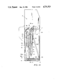
- FIG. 3 is a sectional side view showing a state in which a bill is being paid out in the same embodiment
- FIG. 4 is a sectional view taken along lines IV--IV in FIG. 1;
- FIGS. 5 and 6 are flow charts showing an example of a program for controlling a bill receiving operation in this embodiment
- FIGS. 7 throgh 9 are flow charts showing an example of a program for controlling an operation for paying out a bill from one of the bill receiving chambers in the same embodiment
- FIGS. 10 through 12 are flow charts showing an example of a program for controlling an operation for paying out a bill from the other bill receiving chamber in the same embodiment
- FIG. 13 is a sectional side view showing another embodiment of the bill receiving device of the invention.
- FIG. 14 is a sectional side view showing a state in which the stroke position of the bill pushing member is changed in the same embodiment
- FIG. 15 is a sectional side view showing a state in which a bill is paid out in the same embodiment
- FIG. 16 is a sectional view taken along lines VI--VI in FIG. 14;
- FIG. 17 is a flow chart showing an example of a program for controlling an operation receiving a bill in one of the bill receiving chambers in the same embodiment.
- the bill receiving device shown in FIGS. 1 through 4 receives two kinds of bills separately and in such a manner that both kinds of bills can be paid out respectively.
- This bill receiving device is located in the lower half of a bill device main body. In the upper half of the bill device is disposed a bill discrimination device X.
- This bill receiving device consists of an elongated casing 1 in which a bill entrance 2 is formed in about the center of the upper portion thereof. Under this bill entrance 2 is provided a bill passage 3 which is slightly longer than the longer side of a bill and functions to carry the bill downwardly, holding it on both surfaces thereof. Front and rear spaces definced by this bill passage 3 constitute bill receiving chambers 41 and 42.
- Bill outlets 40 1 and 40 2 are respectively formed above the bill receiving chambers 41 and 42.
- a space 5 which is of a shorter width than the shorter side of the bill is defined by a pair of ribs 51 and a pair of ribs 52 which are provided in front and rear sides of the bill passage 3.
- a reciprocating device 6 which reciprocates in the forward and rearward directions of the casing.
- a bill pushing member 7 which is of a smaller width than the space 5 is fixedly secured to the upper portion of the reciprocating device 6. By the reciprocating movement of the reciprocating device 6, the bill pushing member 7 is moved between points in about the middle of the bill receiving chambers 41 and 42 across the bill passage 3.
- a bill payout mechanism 8 for carrying a bill received in the bill receiving chamber 41 or 42 to the bill outlet 40 1 or 40 2 .
- the bill discrimination device X a device disclosed in Japanese Preliminary Patent Application No. 77288/1985 filed by the applicant of this application, for example, may be employed.
- the bill discrimination device X discriminates a true bill from a false one as well as the denomination of the bill and, responsive to a bill receiving signal produced upon carrying out of the vending operation by a vending machine or a money exchanger, carries the bill to the bill entrance 2 of the bill receiving device according to the present invention.
- a switch SW1 which optically detects presence or absence of a bill. This switch SW1 continuously produces a detection signal while the bill delivered from the bill discrimination device X shields the light path of the switch.
- the bill passage 3 is formed between a convey and drive means 30 1 and bill holding means 30 2 .
- the convey and drive means 30 1 consists of a pair of drive pulleys 31 driven by a motor MO1, a pair of driven pulleys 32 and a pair of conveyer belts 33 stretched between the drive pulleys 31 and the driven pulleys 32.
- the bill holding means 30 2 consists of a pair of ribs 35 having rollers 34 provided in locations opposite to the conveyor belts 33 and being displaceable in the forward and rearward directions and a pair of solenoids SOL for displacing these ribs 35 in the forward and rearward directions.
- the bill passage 3 is constructed so that its length is larger than the longer side of the bill.
- the motor MO1 In response to turning on of the switch SW1, the motor MO1 is turned on and the solenoids SOL are excited to move the ribs 35 from the position shown by a solid line to the position shown by a two-dot chain line in FIG. 1, thereby conveying the inserted bill downwardly while holding it between the conveyer belts 33 and the rollers 34.
- the motor MO1 Upon elapse of a predetermined period of time after the rear edge of the bill has passed through the switch SW1, the motor MO1 is turned off and feeding of the bill thereby is stopped. In this state, the bill is being held in the bill passage 3.
- the motor MO1 may be stopped by a switch SW5 to be described later which detects the leading edge of the bill.
- the reciprocating device 6 consists of a rotating plate 61 which is rotated by a motor MO2 provided in the lower portion of the casing 1, a pin 62 which is secured to the upper surface of the rotating plate 61, and a slide portion 65 which has a slot 63 in which the pin 62 is engaged and moves forwardly and rearwardly along a rod 64 provided in the lower portion of the casing 1 and extending in the direction crossing the surfaces of the bill.
- the bill pushing member 7 is fixedly secured to the slide portion 65 and, by the rotation of the motor MO2, is caused to reciprocate between the position A shown in FIG. 1 and the position B shown by a two-dot chain line in FIG. 2 in accordance with instructions issued by a control circuit to be described later.
- Switches SW2 and SW3 are provided for detecting positions of the bill pushing member 7.
- the switch SW2 detects that the bill pushing member 7 is in a standby position A for stacking bills in the rear side bill receiving chamber 41 and the switch SW3 detects that the bill pushing member 7 is in a standby position B for stacking bills in the front side bill reeiving chamber 42.
- the bill payout mechanism 8 which consists of a motor MO3, a reduction gear 81 and a roller 82 which is rotated by the motor MO3 via this reduction gear 81.
- the roller 82 has a contact surface 83 which consists of a material of a large coefficient of friction such as rubber and this contact surface 83 is projecting from the front and rear surfaces of the bill pushing member 7.
- the space 5 is defined by the pairs of ribs 51 and 52 which are provided on the front and rear sides of the bill passage 3 along the conveyer belts 33. The distance between the pair of ribs 51 or 52 is smaller than the shorter side of the bill.
- Press plates 91 and 92 are provided for pushing bills received in the bill receiving chambers 41 and 42 inwardly by the force of springs 9.
- a bill support plate 10 is also provided at the bottom of the bill receiving chambers 41 and 42.
- Brush wheels 11 are provided above the bill entrance 2 and the bill outlets 40 1 and 40 2 for guiding in and out a bill.
- the bill pushing member 7 In the standby mode, the bill pushing member 7 is in a standby state for receiving a first bill which is frequently used, e.g., a 1,000-yen bill (hereinafter referred to as a bill R) to be received in the bill receiving chamber 41, that is, the bill pushing member 7 is in the position A in the other bill receiving chamber 42.
- a bill R a 1,000-yen bill
- the bill pushing member 7 After the bill R has completely entered the bill passage 3, the bill pushing member 7 is moved in the direction of the bill receiving chamber 41 thereby pushing the bill R to the rear side of the ribs 51 and thereafter is caused to return to the position A and stop.
- the bill pushing member 7 is moved from the position A to the bill receiving chamber 41 and stopped at the standby position B where it enters the standby state for stacking the bill L. After the bill L has completely entered the bill passage 3, the bill pushing member 7 moves in the direction of the the bill receiving chamber 42 thereby pushing the bill L to the rear side of the ribs 52 in the bill receiving chamber 42 and thereafter stops at the standby position A.
- a second bill which is less frequently used e.g., a 10,000-yen bill or a 5,000-yen bill (hereinafter referred to as a bill L)
- the bill pushing member 7 is moved from the position A to the bill receiving chamber 41 and stopped at the standby position B where it enters the standby state for stacking the bill L.
- the bill pushing member 7 moves in the direction of the the bill receiving chamber 42 thereby pushing the bill L to the rear side of the ribs 52 in the bill receiving chamber 42 and thereafter stops at the standby position A.
- the bill pushing member 7 In a case where the bill R in the first bill receiving chamber 41 is paid out, the bill pushing member 7 is moved to a bill payout position C (see a solid line 7 in FIG. 3) in which the rear surface of the bill pushing member 7 is positioned beneath the bill outlet 40 1 . In this state, one bill R which is in contact with the bill pushing member 7 is conveyed to the bill outlet 40 1 by a counterclockwise rotation of the roller 82 of the bill payout mechanism 8.
- Paying out of the bill L in the second bill receiving chamber 42 is performed by moving of the bill pushing member 7 to a bill payout position D (see a two-dot chain line 7 in FIG. 3) in which the front surface of the bill pushing member 7 is positioned beneath the bill outlet 40 2 and clockwise rotation of the roller 82 of the bill payout mechanism 8.
- the bill receiving standby positions A and B and the bill payout positions C and D of the bill pushing member 7 may be detected by a plurality of position detection switches which detect that the reciprocating device 6 has reached the respective positions A through D.
- the position detection may be performed by a single switch detecting a reference position of the reciprocating device 6 and a plurality of timers which are started by turning on or off of this switch.
- FIGS. 1 through 4 The operation of the device shown in FIGS. 1 through 4 may be controlled by using a microcomputer in a manner described below with reference to flow charts of FIGS. 5 through 12.
- the standby state of the bill receiving device is a state in which the bill pushing member 7 is in the position A for stacking the bill R which is frequently used.
- step 100 Upon insertion of a bill in the bill discrimination device X, whether the bill is a true bill or a false one as well as the denomination of the bill is examined in an optical-mangetic method (step 100). If the bill is judged to be a false one, the feed mechanism of the bill discrimination device X is reversely driven and the bill thereby is returned to the insertion slit.
- the bill discrimination device X When the bill discrimination device X has judged that the bill is a true one, the bill stacking operation is not immediately started. The bill is temporarily retained in the bill discrimination device X in a returnable state until a signal indicating that vending or money exchange has been carried out in the vending machine or the money exchanger (hereinafter referred to as a vend start signal) is provided.
- a vend start signal a signal indicating that vending or money exchange has been carried out in the vending machine or the money exchanger
- step 101 the processing proceeds from step 101 to step 102 in which the operation is suspended until the bill receiving signal is provided. If a bill return signal is produced during this waiting time, the bill return process is carried out and the processing returns to the standby state (steps 103 and 104).
- the bill R Upon receipt of the bill receiving signal, the bill R is fed to the bill entrance 2 by the feeding mechanism of the bill discrimination device X.
- a timer T0 Upon detecting the bill which has entered the bill entrance 2 by the switch SW1 which is provided immediately before the bill entrance 2 (YES in step 105), a timer T0 is started and the solenoids SOL are actuated and the motor MO1 is started (steps 106 and 107). The bill is thereby fed downwardly along the bill passage 3.
- a timer T1 is started (steps 108 and 109).
- the set time of the timer T0 is a period of time which is normally required for one stack cycle of the bill.
- the timer T0 is provided for watching whether the stacking operation will be completed within this time or not.
- the set time of the timer T1 is a period of time required for the bill to reach a predetermined position in the bill passage 3 opposite to the bill pushing member 7.
- step 11 whether or not the set time of the timer T1 has elapsed is examined.
- step 112 whether or not the bill has been detected by the switch SW5 provided at the lower end of the bill passage 3 is examined in step 112.
- the operation proceeds to step 113 depending either upon elapse of the set time of the timer T1 or upon detection of the bill by the switch SW5 in which step the motor MO1 and the solenoids SOL are turned off.
- the bill thereby stops at the predetermined position in the bill passage 3 opposite to the bill pushing member 7 in which position the bill is released from the state in which it is clamped between the belts 33 and the rollers 34.
- the turning off of the motor MO1 and the solenoids SOL may be controlled by only one of the conditions of the timer T1 and the switch SW5.
- step 114 turning off of the solenoids SOL is confirmed (step 114) and the motor MO2 is turned on (step 115).
- the bill pushing member 7 thereby is moved from the standby position A to the right as viewed in FIG. 1, pushing the bill located in the bill passage 3 to stack it in the bill receiving chamber 41 on the rear side of the bill passage 3.
- the bill pushing member 7 is moved to the left in FIG. 1 to return to the position A and stop.
- This stacking operation for one cycle is controlled by output signals of the switches SW2 and SW3.
- step 101 proceeds from step 101 to step 123 in FIG. 6 in which the motor MO2 of the reciprocating device 6 is rotated.
- the bill pushing member 7 is moved from the standby position A in FIG. 1 to the right as viewed in the figure.
- the motor MO2 is stopped (steps 124 through 126).
- the bill pushing member 7 is set at the standby position B shown by the two-dot chain line in FIG. 2.
- the bill upon receipt of the bill receiving signal, the bill is fed into the bill passage 3 and, when the bill has been conveyed to the predetermined position in the bill passage 3 opposite to the bill pushing member 7, conveying of the bill is stopped and the bill is released from a state in which it is clamped between the belts 33 and the rollers 34. Further, processings similar to those of steps 114 and 115 in FIG. 5 are performed whereby the reciprocating device 6 is driven by rotation of the motor MO2. The bill pushing member 7 thereby is moved from the standby position B in FIG. 2 to the left as viewed in the figure, pushing the bill in the bill passage 3 and stacking it in the bill receiving chamber 42 on the front side of the bill passage 3.
- step 127 through 129 the motor MO2 is stopped (steps 127 through 129).
- step 130 through 133 the solenoids SOL are actuated during the operation time of the timer T3.
- step 134 the stacking operation is completed (step 134). If the stacking operation has not been completed within the set time of the timer T0, it is assumed that a trouble has occurred and the operation proceeds to "SET STOP" (step 135) in the same manner as was previously described.
- step 136 which of the bills R and L is to be paid out according to the order of the payout signal is examined and, if it is the bill R, the operation proceeds to step 137 in which the motor MO2 is driven.
- step 137 the motor MO2 is driven.
- the bill pushing member 7 thereby is moved from the position A in FIG. 2 to the right as viewed in the figure and reaches the position B pushing the bill R in the bill receiving chamber 41.
- the bill pushing member 7 is moved back to the left as viewed in the figure and stops at the position C in FIG. 3. This operation is controlled in accordance with output signals of the switches SW2, SW3 and the timer T4.
- the facts that the switch SW2 has been turned off, the switch SW3 has been turned on and the switch SW3 has been turned off i.e., the bill pushing member 7 has left the position A corresponding to the switch SW2, reached the position B corresponding to the switch SW3 and then left the position B
- the motor MO2 is stopped.
- the operation time of the timer T4 is set at time required for moving of the bill pushing member 7 from the position B to the position C.
- the motor MO3 of the bill payout mechanism 8 is forwardly rotated (rotation of the motor MO3 imparting a counterclockwise rotation to the roller 82 as viewed in the figure is herein called forward rotation and rotation of the motor MO3 imparting a clockwise rotation to the roller 82 is herein called reverse rotation) and the roller 8 is rotated counterclockwise whereby the leftmost bill among the stack of bills R in the bill receiving chamber 41 which is in contact with the contact surface 83 of the roller 82 is fed upwardly (step 144).
- the upwardly conveyed bill passes the outlet 40 1 and the brush wheels 11 and enters the bill discriminating device X.
- a plural-layered bills detection switch SW4 consisting of a switch detecting the amount of transmitting light is provided for detecting whether or not two or more bills one lying on top of another are fed upwardly (in the present embodiment, no special switch SW4 is provided but the switch SW1 is concurrently used for this switch SW4).
- step 145 becomes YES and the operation proceeds to step 146 in which the motor MO3 is intermittently driven. This intermmittent drive of the motor MO3 is performed for causing an extra bill (or bills) which is not in contact with the contact surface 83 of the roller 82 to fall in a case where two or more bills are fed upwardly in a state in which one lies on top of another.
- the output of the switch SW4 is analyzed to enable judgement as to whether one bill or two or more bills in layer are being paid out. This judgement is made by a known device such as a light amount level discriminator which measures the level of transmitting light detected by the switch SW4.
- step 147 If it has been judged that there are no plural layered bills, the operation proceeds from NO of step 147 to steps 148 and 149 in which the motor MO3 is rotated until the switch SW4 is turned off by passing of the rear edge of the bill through the switch SW4 and the motor MO3 is stopped upon turning off of the switch SW4.
- the bill feeding mechanism of the bill discrimination device X starts its reverse drive in response to the payout signal and the turning on of the switch SW4 for conveying the bill fed back from the bill receiving device further to the bill insertion slit.
- step 150 in FIG. 7 whether the payout signal is continuously provided or not is examined. If result is NO, the motor MO2 is rotated to move the bill pushing member 7 from the position C in FIG. 3 to the left as viewed in the figure (step 151). Upon reaching of the bill pushing member 7 to the standby position A, the switch SW2 is turned on (step 152) and the motor MO2 thereby is stopped (step 153).
- the operation proceeds from YES of step 150 to steps 154 and 155 in FIG. 9 in which the motor MO2 is rotated to move the bill pushing member 7 from the position C in FIG. 3 to the left as viewed in the figure and reaching of the bill pushing member 7 to the standby position A is confirmed by turning on of the switch SW2. Then, the operation returns to step 138 in FIG. 7 and the above described bill payout processings are repeated. In this repeated bill payout operation, the bill pushing member 7 is reciprocated each time one bill is paid out. This reciprocating movement is performed for preventing payout of bills in a plural layered state which tends to occur if payout of bills is repeatedly made in a state in which the bill pushing member 7 keeps on pushing bills in the position C in FIG. 3.
- step 136 in FIG. 7 the operation proceeds from step 136 in FIG. 7 to step 156 in FIG. 10 in which the motor MO2 is driven.
- step 156 in FIG. 10 the motor MO2 is driven.
- the motor MO2 is stopped.
- the bill pushing member 7 thereby is moved from the position A to the right as viewed in the figure and stopped at the position D in FIG. 3. That is, after starting rotation of the motor MO2, the switch SW2 is turned off and upon elapse of the set time of the timer T5 which starts when this switch SW2 is turned off, the motor MO2 is stopped.
- the operation time of the timer T5 is set to time required for moving of the bill pushing member 7 from the position A to the position D.
- step 161 In a state in which the bill pushing member 7 is at the position D, the motor MO3 of the bill payout mechanism 8 is reversely rotated and the roller 82 thereby is rotated clockwise whereby the rightmost bill among the stack of bills L in the bill receiving chamber 42 which is in contact with the contact surface 83 of the roller 82 is fed upwardly (step 161).
- the upwardly conveyed bill passes through the payout slit 40 2 and the brush wheels 11 and enters the bill discrimination device X.
- the following steps 162 through 167 are the same as steps 145 through 150 in FIG. 7 and the bill is paid out in such a manner that plural layered bills are not paid out.
- Steps 168 through 171 in which repeated payout is not made are the same as steps 137 through 140 in FIG. 7 and the bill pushing member 7 is once moved to the position B and then moved back to the standby position A. Then, the motor MO2 is stopped (step 172).
- step 167 When payout of bills is performed repeatedly, the operation proceeds from YES in step 167 to processings in FIG. 12.
- the processings in FIG. 12 are the same as steps 168 through 171 in FIG. 10 and the bill pushing member 7 is once moved to the position B and then is moved back to the standby position A. Then, the operation returns to step 157 in FIG. 10 and the bill payout operation which is the same as the above described one is repeated.
- the operation proceeds from YES in step 147 to processings in FIG. 8.
- the motor MO3 is reversely rotated to return the bill to the bill receiving chamber 41.
- the timer T2 is started and, upon elapse of the set time of the timer T2 , the motor MO3 is stopped.
- the operation time of the timer T3 is time required for returning the bill to the bill receiving chamber 41.
- the motor MO2 is rotated to move the bill pushing member 7 from the position C in FIG. 3 to the left as viewed in the figure.
- step 164 in FIG. 10 the operation proceeds from YES of step 164 in FIG. 10 to the processings in FIG. 11.
- the motor MO3 is forwardly rotated to return the bill to the bill receiving chamber 42.
- the timer T2 is started and, upon elapse of the set time of the timer T2, the motor MO3 is stopped. Then, the motor MO2 is rotated to move the bill pushing member 7 from the position D in FIG. 3 to the right as viewed in the figure.
- the above described routine is repeated as many times as plural layered bills have ceased to be detected.
- the number of repetition may be fixed so that in the event that occurrence of plural layered bills has not ceased notwithstanding repetition of the routine by the fixed number of times, it is assumed that the device is out of order.
- FIGS. 13 through 16 Another embodiment of the invention is shown in FIGS. 13 through 16. This embodiment is somewhat different in construction from the one shown in FIGS. 1 through 4.
- the devices and members performing the same functions as that shown in FIGS. 1 through 4 are designated by the same reference characters. Accordingly, description of the devices and members performing the same functions designated by the same reference characters is not repeated.
- only a bill R received in the bill receiving chamber 41 on the left side as viewed in the figure can be paid out and a bill L received in the bill receiving chamber 42 on the left side cannot be paid out.
- not only bills as currency but also prepaid credit vouchers can be handled.
- a bill discrimination device which can discriminate a true bill or credit voucher from a false one as disclosed in Japanese Preliminary Patent Publication Nos. 220485/1985 and 101890/1986 is used as the bill discrimination device X.
- the right side bill receiving chamber 41 from which a bill can be paid out receives a bill which is expected to be used as a change, e.g., a 1,000-yen bill (this bill is assumed to be a bill R).
- the left side bill receiving chamber 42 from which a bill cannot be paid out receives bills which are not expected to be used as a change, e.g., a 10,000-yen bill, a 5,000-yen bill and a prepaid credit voucher (these are assumed to be bills L).
- a press plate 92 which is provided for pusing a bill or a credit voucher (hereinafter referred to simply as a bill) received in the bill receiving chamber 42 inwardly consists of a leaf spring.
- a press plate 91 which is provided for pushing a bill received in the bill receiving chamber 41 inwardly is interlocked with the reciprocating device 6 through a link mechanism 93 and functions to support a stack of bills in the chamber 41 from the back side of the stack against the pressure excerted by the roller 82 of the bill payout mechanism 8 when a bill is paid out.
- the ribs 52 on the side of the bill receiving chamber 42 are omitted and the ribs 35 for holding the bill concurrently perform the function of the ribs 52.
- FIG. 14 shows a state in which the bill pushing member 7 is in the standby position A.
- the bill pushing member 7 is positioned in the leff side bill receiving chamber 42 and holds a bill L with the press plate 92 whereas a bill R in the right side bill receiving chamber 41 is held between the ribs 51 and the press plate 91.
- the solinoid SOL is actuated to displace the ribs 35 from the position shown by a solid line to the position shown by a two-dot chain line and a bill is conveyed along the bill passage 3.
- the solenoids SOL Upon conveying the bill to a predetermined position, the solenoids SOL are deenergized to return the ribs 35 from the position shown by the two-dot chain line to the position shown by the solid line thereby releasing the bill. Then, in the same manner as was previously described, the bill pushing member 7 performs one reciprocating motion to receive the bill R in the bill receiving chamber 41.
- FIG. 17 which is substantially the same as the one described with reference to FIG. 6 is performed. More specifically, the bill pushing member 7 is moved from the standby position A to the position B in FIG. 13 and thereafter the bill L is conveyed to a predetermined position in the bill passage 3.
- the bill stacking operation executed by processings of steps 180 through 192 is somewhat different from that shown in FIG. 6.
- the reciprocating device 6 is driven by driving the motor MO2 (step 180). The bill pushing member 7 thereby is moved from the position B in FIG. 13 to the left as viewed in the figure to push the bill in the bill passage 3 and cause it to be stacked in the left side bill receiving chamber 42.
- the solenoids SOL are energized during the operation time of the timer T3 (steps 181 through 186).
- the motor MO2 is continuously driven during this time.
- the motor MO2 is stopped (steps 187 through 191).
- the timer T0 is reset and the stacking operation is thus completed (step 192).
- the energizing and deenergizing of the solenoids SOL are made to ensure stacking of bills L, for the bills L include such a thick bill as a credit voucher.
- FIG. 15 shows a state in which the bill pushing member 7 is in the payout position C.
- the roller 82 of the bill payout mechanism 8 provided in the bill pushing member 7 is in contact with the leftmost bill in the stack of bills R in the right side bill receiving chamber 41.
- the edge of this leffmost bill is located beneath the bill outlet 40.
- a small-sized and compact bill receiving device with abundant functions can be provided by dividing the casing of the bill receiving device into the front and rear bill receiving chambers, receiving bills in these chambers after sorting them into two kinds of bills and enabling payout of bills once received in these chambers. Further, by receiving bills of a common denomination in each of these bill receiving chambers when bills of two different denominations are used and enabling payout of bills from both of these chambers, a bill receiving device in which the bills of the two different denominations can be both used as a change can be constructed with a compact construction.
Landscapes
- Physics & Mathematics (AREA)
- General Physics & Mathematics (AREA)
- Engineering & Computer Science (AREA)
- Mechanical Engineering (AREA)
- Pile Receivers (AREA)
Abstract
Description
Claims (8)
Applications Claiming Priority (4)
| Application Number | Priority Date | Filing Date | Title |
|---|---|---|---|
| JP60-172292 | 1985-08-07 | ||
| JP60172292A JPH0641353B2 (en) | 1985-08-07 | 1985-08-07 | Banknote storage device |
| JP60210043A JPH0646428B2 (en) | 1985-09-25 | 1985-09-25 | Cash voucher |
| JP60-210043 | 1985-09-25 |
Publications (1)
| Publication Number | Publication Date |
|---|---|
| US4731523A true US4731523A (en) | 1988-03-15 |
Family
ID=26494693
Family Applications (1)
| Application Number | Title | Priority Date | Filing Date |
|---|---|---|---|
| US06/892,496 Expired - Lifetime US4731523A (en) | 1985-08-07 | 1986-08-01 | Bill receiving device |
Country Status (2)
| Country | Link |
|---|---|
| US (1) | US4731523A (en) |
| KR (1) | KR910009306B1 (en) |
Cited By (11)
| Publication number | Priority date | Publication date | Assignee | Title |
|---|---|---|---|---|
| EP0530457A1 (en) * | 1991-09-04 | 1993-03-10 | Mars, Incorporated | Cassette for flexible sheets |
| US5521382A (en) * | 1994-02-24 | 1996-05-28 | Shimadzu Corporation | MS/MS type mass analyzer |
| US5564691A (en) * | 1993-11-05 | 1996-10-15 | Kabushiki Kaisha Nippon Conlux | Bill processor |
| US5709293A (en) * | 1994-03-10 | 1998-01-20 | Kabushiki Kaisha Nippon Conlux | Bill processing device |
| US6199856B1 (en) | 1998-01-07 | 2001-03-13 | Robert Clauser | Flexible media stacking and accumulating device |
| US20030089769A1 (en) * | 2001-10-09 | 2003-05-15 | Gregory Jantsch | Dispensing of currency |
| US6568591B2 (en) * | 1997-11-28 | 2003-05-27 | Diebold, Incorporated | Document sensor for currency recycling automated banking machine |
| US20050098622A1 (en) * | 2001-10-09 | 2005-05-12 | Gregory Jantsch | Dispensing of currency |
| US20070001383A1 (en) * | 2005-06-20 | 2007-01-04 | Gregory Jantsch | Dispensing of currency |
| WO2009047743A2 (en) | 2007-10-12 | 2009-04-16 | Cts Caspro S.P.A. | Receipting and dispensing banknote module for equipments of automatic deposit and withdrawal of banknotes |
| US20100263983A1 (en) * | 2007-12-07 | 2010-10-21 | Universal Entertainment Corporation | Paper currency handling device |
Citations (1)
| Publication number | Priority date | Publication date | Assignee | Title |
|---|---|---|---|---|
| US4625780A (en) * | 1983-03-22 | 1986-12-02 | Burnham Craig C | Vortex connector |
-
1986
- 1986-08-01 US US06/892,496 patent/US4731523A/en not_active Expired - Lifetime
- 1986-08-02 KR KR1019860006393A patent/KR910009306B1/en not_active Expired
Patent Citations (1)
| Publication number | Priority date | Publication date | Assignee | Title |
|---|---|---|---|---|
| US4625780A (en) * | 1983-03-22 | 1986-12-02 | Burnham Craig C | Vortex connector |
Cited By (27)
| Publication number | Priority date | Publication date | Assignee | Title |
|---|---|---|---|---|
| US5282612A (en) * | 1991-09-04 | 1994-02-01 | Landis & Gyr Betriebs Ag | Plural compartment cartridge for flexible bills |
| EP0530457A1 (en) * | 1991-09-04 | 1993-03-10 | Mars, Incorporated | Cassette for flexible sheets |
| US5564691A (en) * | 1993-11-05 | 1996-10-15 | Kabushiki Kaisha Nippon Conlux | Bill processor |
| US5639081A (en) * | 1993-11-05 | 1997-06-17 | Kabushiki Kaisha Nippon Conlux | Bill processor |
| US5887695A (en) * | 1993-11-05 | 1999-03-30 | Kabushiki Kaisha Nippon Conlux | Bill processor |
| US5521382A (en) * | 1994-02-24 | 1996-05-28 | Shimadzu Corporation | MS/MS type mass analyzer |
| US5709293A (en) * | 1994-03-10 | 1998-01-20 | Kabushiki Kaisha Nippon Conlux | Bill processing device |
| US6076648A (en) * | 1994-03-10 | 2000-06-20 | Kabushiki Kaisha Nippon Conlux | Bill processing device |
| US6568591B2 (en) * | 1997-11-28 | 2003-05-27 | Diebold, Incorporated | Document sensor for currency recycling automated banking machine |
| US6199856B1 (en) | 1998-01-07 | 2001-03-13 | Robert Clauser | Flexible media stacking and accumulating device |
| US20050098622A1 (en) * | 2001-10-09 | 2005-05-12 | Gregory Jantsch | Dispensing of currency |
| US20040099725A1 (en) * | 2001-10-09 | 2004-05-27 | Gregory Jantsch | Dispensing of currency |
| US20030089769A1 (en) * | 2001-10-09 | 2003-05-15 | Gregory Jantsch | Dispensing of currency |
| US7387236B2 (en) | 2001-10-09 | 2008-06-17 | Delaware Capital Formation, Inc. | Dispensing of currency |
| US7407090B2 (en) | 2001-10-09 | 2008-08-05 | Delaware Capital Formation, Inc. | Dispensing of currency |
| US20070001383A1 (en) * | 2005-06-20 | 2007-01-04 | Gregory Jantsch | Dispensing of currency |
| EP1739637A3 (en) * | 2005-06-20 | 2007-09-19 | Delaware Capital Formation, Inc. | Dispensing of currency |
| US20100218707A1 (en) * | 2007-10-12 | 2010-09-02 | Cts Cashpro S.P.A. | Receipting and dispensing banknote module for equipments of automatic deposit and withdrawl of banknotes |
| WO2009047743A3 (en) * | 2007-10-12 | 2009-08-06 | Cts Caspro S P A | Receipting and dispensing banknote module for equipments of automatic deposit and withdrawal of banknotes |
| WO2009047743A2 (en) | 2007-10-12 | 2009-04-16 | Cts Caspro S.P.A. | Receipting and dispensing banknote module for equipments of automatic deposit and withdrawal of banknotes |
| CN101952859A (en) * | 2007-10-12 | 2011-01-19 | Cts卡什普罗股份公司 | Receipting and dispensing banknote module for equipments of automatic deposit and withdrawal of banknotes |
| CN101952859B (en) * | 2007-10-12 | 2014-03-19 | Cts卡什普罗股份公司 | Banknote receiving and dispensing module for equipment for automatic deposit and withdrawal of banknotes |
| AU2008309214B2 (en) * | 2007-10-12 | 2014-09-04 | Sesami Technologies S.R.L. | Receipting and dispensing banknote module for equipments of automatic deposit and withdrawal of banknotes |
| US9240087B2 (en) | 2007-10-12 | 2016-01-19 | C.T.S. Cashpro S.R.L. | Receipting and dispensing banknote module for equipments of automatic deposit and withdrawl of banknotes |
| US20100263983A1 (en) * | 2007-12-07 | 2010-10-21 | Universal Entertainment Corporation | Paper currency handling device |
| US8245830B2 (en) * | 2007-12-07 | 2012-08-21 | Universal Entertainment Corporation | Paper currency handling device |
| CN101889297B (en) * | 2007-12-07 | 2013-05-08 | 环球娱乐株式会社 | Paper currency handling device |
Also Published As
| Publication number | Publication date |
|---|---|
| KR870002531A (en) | 1987-03-31 |
| KR910009306B1 (en) | 1991-11-09 |
Similar Documents
| Publication | Publication Date | Title |
|---|---|---|
| US4540081A (en) | Bill accepting device and method for controlling accepting of bills | |
| KR950014506B1 (en) | Coin Processing Equipment | |
| US4731523A (en) | Bill receiving device | |
| US5894937A (en) | Method and apparatus for processing bank notes | |
| EP0174009B1 (en) | Cash dispenser | |
| EP0329035A1 (en) | Paper let-out apparatus | |
| EP1603085A1 (en) | Bill depositing/dispensing apparatus | |
| EP2249316B1 (en) | Coin transporting device | |
| US5910044A (en) | Coin separator and transport | |
| GB2220095A (en) | Bill receiving and dispensing machine | |
| GB2225472A (en) | Coin removing apparatus for coin handling machine | |
| EP0329034B1 (en) | Bill handler | |
| JPS6327759B2 (en) | ||
| KR20080104266A (en) | Coin dispenser | |
| US4993990A (en) | Unacceptable coin removing apparatus for coin handling machine | |
| US4877232A (en) | Paper discharge apparatus | |
| JPH08161557A (en) | Automatic charge collecting device | |
| JP3857860B2 (en) | Coin stacking and dispensing device | |
| KR880000860B1 (en) | Bill import device and bill import control method | |
| JPH10241005A (en) | Automatic change payment device | |
| JPH0646428B2 (en) | Cash voucher | |
| JP3013101B2 (en) | Coin processing equipment | |
| JP2539581Y2 (en) | Coin storage and dispensing device in coin depositing and dispensing machine | |
| JPH0636105A (en) | Circulation-typed coin receiving/paying machine | |
| JPH021651Y2 (en) |
Legal Events
| Date | Code | Title | Description |
|---|---|---|---|
| AS | Assignment |
Owner name: KABUSHIKI KAISHA NIPPON COINCO, 2-2, UCHISAIWAICHO Free format text: ASSIGNMENT OF ASSIGNORS INTEREST.;ASSIGNOR:KOZIMA, SUSUMU;REEL/FRAME:004601/0842 Effective date: 19860725 Owner name: KABUSHIKI KAISHA NIPPON COINCO, A CORP OF JAPAN, J Free format text: ASSIGNMENT OF ASSIGNORS INTEREST;ASSIGNOR:KOZIMA, SUSUMU;REEL/FRAME:004601/0842 Effective date: 19860725 |
|
| STCF | Information on status: patent grant |
Free format text: PATENTED CASE |
|
| AS | Assignment |
Owner name: NIPPON CONLUX CO., LTD., JAPAN Free format text: CHANGE OF NAME;ASSIGNOR:KABUSHIKI KAISHA NIPPON COINCO;REEL/FRAME:005036/0290 Effective date: 19880903 |
|
| FEPP | Fee payment procedure |
Free format text: PAYOR NUMBER ASSIGNED (ORIGINAL EVENT CODE: ASPN); ENTITY STATUS OF PATENT OWNER: LARGE ENTITY |
|
| FPAY | Fee payment |
Year of fee payment: 4 |
|
| FPAY | Fee payment |
Year of fee payment: 8 |
|
| FPAY | Fee payment |
Year of fee payment: 12 |
|
| AS | Assignment |
Owner name: CITIBANK, N.A., TOKYO BRANCH, JAPAN Free format text: SECURITY AGREEMENT;ASSIGNOR:NIPPON CONLUX CO., LTD.;REEL/FRAME:017957/0752 Effective date: 20060719 |
|
| AS | Assignment |
Owner name: CITIBANK JAPAN LTD., JAPAN Free format text: CHANGE OF SECURITY AGENT;ASSIGNOR:CITIBANK, N.A., TOKYO BUILDING;REEL/FRAME:019704/0952 Effective date: 20070701 |