US4728362A - High voltage electrodes for the ignition system of internal combustion engines and method for making the same - Google Patents
High voltage electrodes for the ignition system of internal combustion engines and method for making the same Download PDFInfo
- Publication number
- US4728362A US4728362A US06/887,132 US88713286A US4728362A US 4728362 A US4728362 A US 4728362A US 88713286 A US88713286 A US 88713286A US 4728362 A US4728362 A US 4728362A
- Authority
- US
- United States
- Prior art keywords
- high voltage
- iron
- granulate
- weight
- powder
- Prior art date
- Legal status (The legal status is an assumption and is not a legal conclusion. Google has not performed a legal analysis and makes no representation as to the accuracy of the status listed.)
- Expired - Fee Related
Links
- 238000002485 combustion reaction Methods 0.000 title claims abstract description 6
- 238000000034 method Methods 0.000 title claims description 8
- XEEYBQQBJWHFJM-UHFFFAOYSA-N Iron Chemical compound [Fe] XEEYBQQBJWHFJM-UHFFFAOYSA-N 0.000 claims abstract description 36
- 229910052742 iron Inorganic materials 0.000 claims abstract description 13
- 229910021346 calcium silicide Inorganic materials 0.000 claims abstract description 11
- 239000000203 mixture Substances 0.000 claims abstract description 9
- 239000000843 powder Substances 0.000 claims description 18
- 239000008187 granular material Substances 0.000 claims description 9
- OYPRJOBELJOOCE-UHFFFAOYSA-N Calcium Chemical compound [Ca] OYPRJOBELJOOCE-UHFFFAOYSA-N 0.000 claims description 6
- 239000011230 binding agent Substances 0.000 claims description 6
- 239000011575 calcium Substances 0.000 claims description 6
- 229910052791 calcium Inorganic materials 0.000 claims description 6
- 239000000314 lubricant Substances 0.000 claims description 5
- 230000001681 protective effect Effects 0.000 claims description 5
- 238000000465 moulding Methods 0.000 claims description 4
- 238000001704 evaporation Methods 0.000 claims description 3
- 239000010703 silicon Substances 0.000 claims description 3
- 229910052710 silicon Inorganic materials 0.000 claims description 3
- 235000015393 sodium molybdate Nutrition 0.000 claims description 3
- 239000011684 sodium molybdate Substances 0.000 claims description 3
- TVXXNOYZHKPKGW-UHFFFAOYSA-N sodium molybdate (anhydrous) Chemical compound [Na+].[Na+].[O-][Mo]([O-])(=O)=O TVXXNOYZHKPKGW-UHFFFAOYSA-N 0.000 claims description 3
- 239000000126 substance Substances 0.000 claims description 3
- 238000004519 manufacturing process Methods 0.000 claims description 2
- 229910052751 metal Inorganic materials 0.000 claims description 2
- 239000002184 metal Substances 0.000 claims description 2
- 239000002245 particle Substances 0.000 claims description 2
- ZOKXTWBITQBERF-UHFFFAOYSA-N Molybdenum Chemical compound [Mo] ZOKXTWBITQBERF-UHFFFAOYSA-N 0.000 claims 2
- 238000002156 mixing Methods 0.000 claims 2
- 229910052750 molybdenum Inorganic materials 0.000 claims 2
- 239000011733 molybdenum Substances 0.000 claims 2
- 238000005245 sintering Methods 0.000 claims 2
- WFKWXMTUELFFGS-UHFFFAOYSA-N tungsten Chemical compound [W] WFKWXMTUELFFGS-UHFFFAOYSA-N 0.000 claims 2
- 229910052721 tungsten Inorganic materials 0.000 claims 2
- 239000010937 tungsten Substances 0.000 claims 2
- XUIMIQQOPSSXEZ-UHFFFAOYSA-N Silicon Chemical compound [Si] XUIMIQQOPSSXEZ-UHFFFAOYSA-N 0.000 claims 1
- 239000007789 gas Substances 0.000 claims 1
- 238000010438 heat treatment Methods 0.000 claims 1
- 238000007906 compression Methods 0.000 description 3
- 239000000463 material Substances 0.000 description 3
- 229910004709 CaSi Inorganic materials 0.000 description 2
- OKTJSMMVPCPJKN-UHFFFAOYSA-N Carbon Chemical compound [C] OKTJSMMVPCPJKN-UHFFFAOYSA-N 0.000 description 2
- 229910052799 carbon Inorganic materials 0.000 description 2
- 230000006835 compression Effects 0.000 description 2
- 239000003921 oil Substances 0.000 description 2
- PBYZMCDFOULPGH-UHFFFAOYSA-N tungstate Chemical compound [O-][W]([O-])(=O)=O PBYZMCDFOULPGH-UHFFFAOYSA-N 0.000 description 2
- 229910014521 Ca2 Si Inorganic materials 0.000 description 1
- 229910004706 CaSi2 Inorganic materials 0.000 description 1
- 229910004829 CaWO4 Inorganic materials 0.000 description 1
- 239000001856 Ethyl cellulose Substances 0.000 description 1
- ZZSNKZQZMQGXPY-UHFFFAOYSA-N Ethyl cellulose Chemical compound CCOCC1OC(OC)C(OCC)C(OCC)C1OC1C(O)C(O)C(OC)C(CO)O1 ZZSNKZQZMQGXPY-UHFFFAOYSA-N 0.000 description 1
- 229910004729 Na2 MoO4 Inorganic materials 0.000 description 1
- 239000004020 conductor Substances 0.000 description 1
- 238000007865 diluting Methods 0.000 description 1
- 238000009826 distribution Methods 0.000 description 1
- 229920001249 ethyl cellulose Polymers 0.000 description 1
- 235000019325 ethyl cellulose Nutrition 0.000 description 1
- 230000008020 evaporation Effects 0.000 description 1
- 239000012530 fluid Substances 0.000 description 1
- -1 for example Substances 0.000 description 1
- 238000002360 preparation method Methods 0.000 description 1
- 229910000679 solder Inorganic materials 0.000 description 1
- 239000007787 solid Substances 0.000 description 1
- XOOUIPVCVHRTMJ-UHFFFAOYSA-L zinc stearate Chemical compound [Zn+2].CCCCCCCCCCCCCCCCCC([O-])=O.CCCCCCCCCCCCCCCCCC([O-])=O XOOUIPVCVHRTMJ-UHFFFAOYSA-L 0.000 description 1
Images
Classifications
-
- F—MECHANICAL ENGINEERING; LIGHTING; HEATING; WEAPONS; BLASTING
- F02—COMBUSTION ENGINES; HOT-GAS OR COMBUSTION-PRODUCT ENGINE PLANTS
- F02P—IGNITION, OTHER THAN COMPRESSION IGNITION, FOR INTERNAL-COMBUSTION ENGINES; TESTING OF IGNITION TIMING IN COMPRESSION-IGNITION ENGINES
- F02P7/00—Arrangements of distributors, circuit-makers or -breakers, e.g. of distributor and circuit-breaker combinations or pick-up devices
- F02P7/02—Arrangements of distributors, circuit-makers or -breakers, e.g. of distributor and circuit-breaker combinations or pick-up devices of distributors
- F02P7/021—Mechanical distributors
- F02P7/022—Details of the distributor rotor or electrode
-
- H—ELECTRICITY
- H01—ELECTRIC ELEMENTS
- H01T—SPARK GAPS; OVERVOLTAGE ARRESTERS USING SPARK GAPS; SPARKING PLUGS; CORONA DEVICES; GENERATING IONS TO BE INTRODUCED INTO NON-ENCLOSED GASES
- H01T7/00—Rotary spark gaps, i.e. devices having one or more rotating electrodes
Definitions
- the invention relates to high voltage electrodes in accordance with the type of the main claim.
- a device for the ignition voltage distribution in ignition system designed for internal combustion engines is described in the DE-OS No. 31 36 745, wherein electrodes are used which have calcium and silicon as main components.
- this material in sintered condition does not have the hardness or toughness required for a high service life.
- a further disadvantage of such electrodes is that it is hard to contact them, since this material is hard to solder and hard to weld.
- the inventive high voltage electrodes which in addition to calcium and silicon contain iron have the advantage that they have a sufficient hardness for a long life span in the sintered condition and that they can be more easily soldered and welded and can be more easily contacted with a carbon brush than the aforementioned material.
- the method in accordance with claim 6 is advantageous in that demixing of the two components is eliminated, which otherwise can easily occur, since the CaSi has a density of about 2.5 g/cm 3 , and iron has a density of about 7.8 g/cm 3 .
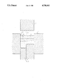
- FIGURE illustrates schematically a section of a mold provided with a separating wall for making a high voltage electrode with a tipstretched contact area.
- a high voltage electrode 70% by weight iron powder with a granular size of ⁇ 0.2 mm, 29% by weight calcium silicide powder in the screen fraction of ⁇ 0.2 mm as well as 1.0% by weight calcium wolframate CaWO 4 or sodium molybdate Na 2 MoO 4 are thoroughly mixed.
- a nonalloyed iron powder is used as an iron powder, the calcium silicide powder substantially consists of CaSi 2 with small components of Ca 2 Si and CaSi.
- the adding of calcium wolframate or sodium molybdate serves for the reduction of the burning voltage, whereby the interference in the ignition distributor in which the electrode is used is improved.
- the powder mixture After adding 1% by weight of a solid organic binder substance like, for example, ethyl cellulose which had been dissolved in a diluting oil, the powder mixture is granulated by the fluid bed method until a size of the granulate from 0.2 to 0.4 mm is obtained.
- a solid organic binder substance like, for example, ethyl cellulose which had been dissolved in a diluting oil
- iron has a density of about 7.8 g/cm 3
- calcium silicide density is only at about 2.5 g/cm 3
- an untreated powder mixture has the tendency that the iron powder gradually settles downwardly. Due to the granulating process this danger of demixing id completely eliminated, moreover round granulate particles are formed and have a good fluidity after the evaporation of the thinning oil that increased temperature and can therefore be very well processed in the following operating steps.
- the finished granulate to which a slight amount of a customary organic lubricant had been added, for example, zinc stearate is filled into a press mold, as schematically illustrated in the drawing.
- the mold consists of wall 1 and two movably disposed lower plungers or dies 2 forming together with the wall a hollow chamber 3 corresponding to the shape of the part to be made.
- the granulate 5 whose manufacturing had just been described is filled into the deeper part of the hollow chamber, while in the other part of the hollow chamber nonalloyed iron powder 6 is filled, and also the lubricant is added. Due to the fact that the compression relationships of the two types of powder 5 and 6 are different, different filling heights result for the two powders.
- the compression relationship is defined as the relationship of the height of a powder column with respect to the height of the molded body which is generated under a defined pressure. During the compression process both lower dies are brought to the same height. Thus, it is assured that in both types of powders 5 and 6 a defined molding density and a sufficient stability for the further processing is guaranteed. For example, if one would operate with nonseparated lower dies to fill in the powders 5 and 6 at the same level and would then start to mold, a sufficient stability would be obtained for the iron powder 6, however the calcium silicide powder 5 would not have the required stability. In the concrete case, the relationship of the filling levels, as is required for the further processing, has to be established experimentally.
- the generated blank represents a composition of the actual high voltage electrode consisting of the iron and the calcium silicide and the contact part which consist solely of iron.
- the blank is removed from the mold and is at first heated to a temperature of 400° C. under a protective gas of a N 2 /H 2 mixture for evaporating the binder and lubricant substances and is finally sintered in a furnace, also under a protective gas, at a temperature of about 1050° C. for 0.5 hours. Thereafter, the finished high voltage electrode can be used either in combination with an interference suppressing resistor, or in direct contact with the carbon brush of a high voltage feed of an ignition distributor.
Landscapes
- Engineering & Computer Science (AREA)
- Chemical & Material Sciences (AREA)
- Combustion & Propulsion (AREA)
- Mechanical Engineering (AREA)
- General Engineering & Computer Science (AREA)
- Powder Metallurgy (AREA)
- Ignition Installations For Internal Combustion Engines (AREA)
Abstract
Description
Claims (9)
Applications Claiming Priority (2)
| Application Number | Priority Date | Filing Date | Title |
|---|---|---|---|
| DE3447342 | 1984-12-24 | ||
| DE3447342A DE3447342C2 (en) | 1984-12-24 | 1984-12-24 | High-voltage electrodes for the ignition distributor of the ignition system of internal combustion engines and method for producing the same |
Publications (1)
| Publication Number | Publication Date |
|---|---|
| US4728362A true US4728362A (en) | 1988-03-01 |
Family
ID=6253858
Family Applications (1)
| Application Number | Title | Priority Date | Filing Date |
|---|---|---|---|
| US06/887,132 Expired - Fee Related US4728362A (en) | 1984-12-24 | 1985-12-05 | High voltage electrodes for the ignition system of internal combustion engines and method for making the same |
Country Status (5)
| Country | Link |
|---|---|
| US (1) | US4728362A (en) |
| AU (1) | AU579699B2 (en) |
| BR (1) | BR8507142A (en) |
| DE (1) | DE3447342C2 (en) |
| WO (1) | WO1986003807A1 (en) |
Cited By (1)
| Publication number | Priority date | Publication date | Assignee | Title |
|---|---|---|---|---|
| US20090035169A1 (en) * | 2007-08-03 | 2009-02-05 | Honda Motor Co., Ltd. | Dual metal torque transmitting apparatuses and methods for making the same |
Families Citing this family (1)
| Publication number | Priority date | Publication date | Assignee | Title |
|---|---|---|---|---|
| DE3837808A1 (en) * | 1988-11-08 | 1990-05-10 | Bosch Gmbh Robert | IGNITION DISTRIBUTOR FOR IGNITION SYSTEMS FOR INTERNAL COMBUSTION ENGINES |
Citations (4)
| Publication number | Priority date | Publication date | Assignee | Title |
|---|---|---|---|---|
| US1972463A (en) * | 1930-07-12 | 1934-09-04 | Ig Farbenindustrie Ag | Welding |
| US2116399A (en) * | 1935-11-29 | 1938-05-03 | Marth Paul | Process for making shaped bodies from hard substances |
| US3256699A (en) * | 1962-01-29 | 1966-06-21 | Monsanto Co | Thermoelectric unit and process of using to interconvert heat and electrical energy |
| US4282420A (en) * | 1980-02-11 | 1981-08-04 | Chemetron Corporation | Welding electrode |
Family Cites Families (5)
| Publication number | Priority date | Publication date | Assignee | Title |
|---|---|---|---|---|
| JPS5438447A (en) * | 1977-09-02 | 1979-03-23 | Hitachi Ltd | Distributor for internal combustion engine |
| DE2949573C2 (en) * | 1978-12-11 | 1982-06-03 | Hitachi, Ltd., Tokyo | Ignition distributor |
| JPS5642980A (en) * | 1979-09-14 | 1981-04-21 | Ngk Spark Plug Co | Metal ball electrode ignition plug and production thereof |
| DE3136745A1 (en) * | 1981-09-16 | 1983-03-31 | Robert Bosch Gmbh, 7000 Stuttgart | DEVICE FOR DISTRIBUTING VOLTAGE DISTRIBUTION IN COMBINED IGNITION SYSTEMS FOR INTERNAL COMBUSTION ENGINES |
| DE3347409A1 (en) * | 1983-12-29 | 1985-07-11 | Robert Bosch Gmbh, 7000 Stuttgart | DEVICE FOR DISTRIBUTING VOLTAGE DISTRIBUTION IN COMBINED IGNITION SYSTEMS FOR COMBUSTION ENGINES |
-
1984
- 1984-12-24 DE DE3447342A patent/DE3447342C2/en not_active Expired - Fee Related
-
1985
- 1985-12-05 US US06/887,132 patent/US4728362A/en not_active Expired - Fee Related
- 1985-12-05 WO PCT/DE1985/000508 patent/WO1986003807A1/en not_active Ceased
- 1985-12-05 BR BR8507142A patent/BR8507142A/en not_active IP Right Cessation
- 1985-12-05 AU AU52043/86A patent/AU579699B2/en not_active Ceased
Patent Citations (4)
| Publication number | Priority date | Publication date | Assignee | Title |
|---|---|---|---|---|
| US1972463A (en) * | 1930-07-12 | 1934-09-04 | Ig Farbenindustrie Ag | Welding |
| US2116399A (en) * | 1935-11-29 | 1938-05-03 | Marth Paul | Process for making shaped bodies from hard substances |
| US3256699A (en) * | 1962-01-29 | 1966-06-21 | Monsanto Co | Thermoelectric unit and process of using to interconvert heat and electrical energy |
| US4282420A (en) * | 1980-02-11 | 1981-08-04 | Chemetron Corporation | Welding electrode |
Cited By (1)
| Publication number | Priority date | Publication date | Assignee | Title |
|---|---|---|---|---|
| US20090035169A1 (en) * | 2007-08-03 | 2009-02-05 | Honda Motor Co., Ltd. | Dual metal torque transmitting apparatuses and methods for making the same |
Also Published As
| Publication number | Publication date |
|---|---|
| DE3447342A1 (en) | 1986-06-26 |
| BR8507142A (en) | 1987-07-14 |
| DE3447342C2 (en) | 1994-06-01 |
| WO1986003807A1 (en) | 1986-07-03 |
| AU579699B2 (en) | 1988-12-08 |
| AU5204386A (en) | 1986-07-22 |
Similar Documents
| Publication | Publication Date | Title |
|---|---|---|
| EP2033284B1 (en) | Spark plug | |
| DE69800238T2 (en) | spark plug | |
| EP1835579B1 (en) | Spark plug for use in an internal-combustion engine and a method for manufacturing the same | |
| DE102004044152B4 (en) | spark plug | |
| US2248415A (en) | Spark plug electrode seal | |
| EP2348590B1 (en) | Spark plug for internal combustion engine | |
| EP0899839A1 (en) | Spark plug | |
| DE19719937A1 (en) | Motor vehicle IC engine sparking plug with manufacturing method | |
| DE102013219520B4 (en) | Spark plug for internal combustion engine | |
| US4728362A (en) | High voltage electrodes for the ignition system of internal combustion engines and method for making the same | |
| CN102204042B (en) | Spark plugs for internal combustion engines | |
| EP2482395A1 (en) | Spark plug | |
| JP5129819B2 (en) | Spark plug insulator and manufacturing method thereof, and spark plug and manufacturing method thereof | |
| WO1994021015A1 (en) | Electrically conductive sealing compound for sparking plugs | |
| DE112022003085T5 (en) | SPARK PLUG | |
| DE69025347T2 (en) | Spark plug and manufacturing process | |
| DE2228941A1 (en) | Thermistor | |
| US3705951A (en) | Spark plug sealing gasket | |
| DE102013219941B4 (en) | spark plug | |
| JP5492244B2 (en) | Spark plug | |
| US2906907A (en) | Process for the manufacture of low tension sparking plugs | |
| JP2010073684A (en) | Method of manufacturing spark plug | |
| DE102015214057B4 (en) | Method for producing a spark plug by means of a capsule filled with powder and spark plug | |
| US2988663A (en) | Spark plug | |
| JPH09306636A (en) | Spark plug |
Legal Events
| Date | Code | Title | Description |
|---|---|---|---|
| AS | Assignment |
Owner name: ROBERT BOSCH GMBH, POSTFACH 50 D-7000 STUTTGART 1, Free format text: ASSIGNMENT OF ASSIGNORS INTEREST.;ASSIGNORS:GRUNWALD, WERNER;KOCH, HANS-PETER;LEUZE, GUNDMAR;AND OTHERS;REEL/FRAME:004580/0900 Effective date: 19860402 Owner name: ROBERT BOSCH GMBH,GERMANY Free format text: ASSIGNMENT OF ASSIGNORS INTEREST;ASSIGNORS:GRUNWALD, WERNER;KOCH, HANS-PETER;LEUZE, GUNDMAR;AND OTHERS;REEL/FRAME:004580/0900 Effective date: 19860402 |
|
| FEPP | Fee payment procedure |
Free format text: PAYOR NUMBER ASSIGNED (ORIGINAL EVENT CODE: ASPN); ENTITY STATUS OF PATENT OWNER: LARGE ENTITY |
|
| FPAY | Fee payment |
Year of fee payment: 4 |
|
| FEPP | Fee payment procedure |
Free format text: PAYER NUMBER DE-ASSIGNED (ORIGINAL EVENT CODE: RMPN); ENTITY STATUS OF PATENT OWNER: LARGE ENTITY Free format text: PAYOR NUMBER ASSIGNED (ORIGINAL EVENT CODE: ASPN); ENTITY STATUS OF PATENT OWNER: LARGE ENTITY |
|
| REMI | Maintenance fee reminder mailed | ||
| LAPS | Lapse for failure to pay maintenance fees | ||
| FP | Lapsed due to failure to pay maintenance fee |
Effective date: 19960306 |
|
| STCH | Information on status: patent discontinuation |
Free format text: PATENT EXPIRED DUE TO NONPAYMENT OF MAINTENANCE FEES UNDER 37 CFR 1.362 |