US4724910A - Implement with resiliently mounted coulter gangs - Google Patents
Implement with resiliently mounted coulter gangs Download PDFInfo
- Publication number
- US4724910A US4724910A US06/912,962 US91296286A US4724910A US 4724910 A US4724910 A US 4724910A US 91296286 A US91296286 A US 91296286A US 4724910 A US4724910 A US 4724910A
- Authority
- US
- United States
- Prior art keywords
- tool
- main frame
- implement
- subframe
- gang
- Prior art date
- Legal status (The legal status is an assumption and is not a legal conclusion. Google has not performed a legal analysis and makes no representation as to the accuracy of the status listed.)
- Expired - Fee Related
Links
- 230000036316 preload Effects 0.000 description 6
- 239000012530 fluid Substances 0.000 description 4
- 230000006835 compression Effects 0.000 description 3
- 238000007906 compression Methods 0.000 description 3
- 230000035515 penetration Effects 0.000 description 2
- 230000004323 axial length Effects 0.000 description 1
- 230000003247 decreasing effect Effects 0.000 description 1
- 238000003971 tillage Methods 0.000 description 1
Images

Classifications
-
- A—HUMAN NECESSITIES
- A01—AGRICULTURE; FORESTRY; ANIMAL HUSBANDRY; HUNTING; TRAPPING; FISHING
- A01B—SOIL WORKING IN AGRICULTURE OR FORESTRY; PARTS, DETAILS, OR ACCESSORIES OF AGRICULTURAL MACHINES OR IMPLEMENTS, IN GENERAL
- A01B61/00—Devices for, or parts of, agricultural machines or implements for preventing overstrain
- A01B61/04—Devices for, or parts of, agricultural machines or implements for preventing overstrain of the connection between tools and carrier beam or frame
- A01B61/044—Devices for, or parts of, agricultural machines or implements for preventing overstrain of the connection between tools and carrier beam or frame the connection enabling a yielding pivoting movement around a substantially horizontal and transverse axis
- A01B61/046—Devices for, or parts of, agricultural machines or implements for preventing overstrain of the connection between tools and carrier beam or frame the connection enabling a yielding pivoting movement around a substantially horizontal and transverse axis the device including an energy accumulator for restoring the tool to its working position
-
- A—HUMAN NECESSITIES
- A01—AGRICULTURE; FORESTRY; ANIMAL HUSBANDRY; HUNTING; TRAPPING; FISHING
- A01B—SOIL WORKING IN AGRICULTURE OR FORESTRY; PARTS, DETAILS, OR ACCESSORIES OF AGRICULTURAL MACHINES OR IMPLEMENTS, IN GENERAL
- A01B49/00—Combined machines
- A01B49/02—Combined machines with two or more soil-working tools of different kind
Definitions
- This invention relates to a multiple tool implement having a resiliently mounted coulter gang and more particularly to an implement having a resiliently mounted coulter gang which is adjustable relative to the implement frame by a hydraulic actuator having a resiliently cushioned support on the implement frame.
- At least one other party has provided a multiple tool agricultural implement which has a spring cushion for a vertically adjustable subframe.
- a spring cushion for a vertically adjustable subframe is shown in U.S. Pat. No. 4,546,832 issued Oct. 15, 1985 to William J. Dietrich, Sr. and Cary L. Sizelove for an "Agricultural Implement with Spring Cushion for Vertically Adjustable Subframe".
- some field obstacles can be passed over by the disc gang subframe because of the movement permitted by the spring cushioned anchor for the hydraulic adjusting ram connected to the subframe.
- the spring may not afford enough upward movement of the subframe when a large obstacle is encountered in which case the relief valve for the hydraulic system will open to allow further upward movement of the subframe.
- a primary object of this invention is to provide a cushioned tool gang on a multiple tool implement which is vertically adjusted by a hydraulic actuator resiliently anchored to the implement main frame so as to afford a great amount of resiliently opposed upward movement upon encountering an obstacle in the field being worked.
- First and second earthworking tools are operably mounted on the main frame in spaced relation to one another in the direction of movement of the implement during operation.
- One of the tools is connected to the main frame so as to be movable by power operated means between working and nonworking positions.
- the power operated means may take the form of an extendable and contractable hydraulic actuator having one of its ends connected to the one tool.
- the other end of the actuator is connected to the main frame by a resilient cushion support which includes an upstanding lever having its top and bottom ends pivotally connected to the actuator and main frame on upper and lower transverse axes.
- a spring loaded link is interconnected between the main frame and a point on the lever spaced from the lower axes.
- the spring loaded link includes a spring which is compressed upon the lever exerting an excess of a predetermined thrust against the link in a direction corresponding to raising movement of the one tool.
- the preloaded link may be adjustable to reposition the end of the actuator connected to the lever and adjustment means are provided to change the preload on the spring.
- the one tool may include a subframe to which the actuator is connected and the one tool may further include a coulter gang rotatably mounted on the subframe by a pair of U-shaped springs.
- FIG. 1 is a side view of part of an implement carrying two different types of tools
- FIG. 2 is a partial top view of the implement shown in FIG. 1;
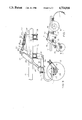
- FIG. 3 is a view taken along the line III--III in FIG. 2.
- FIG. 1 shows the invention in a conservation tillage implement which includes at least one coulter gang 11 and a plurality of spring tooth cultivator shanks 12, one of which is shown, mounted on an implement main frame 13.
- the implement main frame 13 is selectively raised and lowered between transport and operating positions by laterally spaced wheels 14, 16 rotatably mounted on arms pivotally connected at their forward ends to the implement main frame 13 on a transverse axis 17.
- the arms are pivoted about the axis 17 by conventional means such as hydraulic actuators, not shown.
- the coulter gang 11 includes a plurality of laterally spaced coulters 21 secured to a transverse shaft 22 which is rotatably mounted on a pair of bearing blocks 26, only one of which is shown.
- the bearing blocks 26 are secured to the lower legs of a pair of U-shaped springs 23, 24 by bolts 27 and nuts 28.
- the upper legs of the U-shaped springs 23, 24 are secured by nuts and bolts to a tool subframe 31 which includes a transverse beam 32 with a pair of rearwardly extending arms 33, 34.
- the rear ends of the arms 33, 34 are pivotally mounted on a pair of brackets 36, 37 bolted to a transverse beam 38 of the implement main frame 13 by a pair of aligned pins 41, 42 for raising and lowering movement of the subframe and coulter gang about the transverse axis of the pins 41, 42.
- the coulter gang is in an earthworking position.
- the subframe and coulter gang 11 are raised and lowered relative to the implement main frame 13 by power means in the form of a hydraulic ram or actuator 43.
- the expandable and contractable actuator 43 is a linear actuator having a piston whose rod portion 44 is pivotally connected to the subframe 32 carrying the coulter gang 11 by a transverse pin 45 and a cylinder 46 whose closed end is pivotally connected to the upper end of a lever 47 by a transverse pin 48.
- the lower end of the lever 47 is pivotally connected to upstanding flanges 49, 50 of a channel shaped support 51 by a transverse pin 52.
- the support 51 is securely bolted to transverse beams 38, 39 of the implement main frame 13.
- the lever 47 on which the coulter gang lift ram 43 is mounted is cushioned by resilient cushion means in the form of spring loaded link 56 which includes a rod 57 having a clevis 58 at its front end pivotally connected to an intermediate part of the lever 47 by a transverse pivot pin 59 and a threaded part 61 threadedly engaged in a threaded opening in the base of the clevis 58.
- the threaded part 61 extends loosely through an unthreaded opening in a transverse vertical abutment plate 62 welded to the inner sides of the flanges 49, 50 and a resilient coil compression spring 63 surrounds the threaded part 61 axially between, and in axial thrust transmitting engagement with, the abutment plate 62 and a thrust washer 64 held against axial movement in the direction away from the spring by a nut 66 in threaded engagement with the threaded part 61.
- a nut 67 threadedly engaging the threaded part 61 and abutting the rear side of the abutment plate 62 holds the spring 63 and threaded part 61 in assembly with the abutment plate 62 thus maintaining a preload on the spring 63.
- the ram 43 will be extended as illustrated in the drawings and the transport wheels 14, 16 will be raised as shown in FIG. 1. If the operator wishes to increase or decrease the depth of penetration of the coulters 21 of the coulter gang 11, the operator causes the ram to be contracted or extended through conventional controls, not shown. If during operation a large boulder should be encountered by one or more of the coulters 21, the U-shaped spring will deflect to permit a predetermined amount of upward movement of the relevant part of the coulter gang 11. The compression spring 63 of the cushioned ram support 56 will also deflect (compress) to a reduced axial length thereby allowing the upper end of the lever and the ram connecting pivot pin 48 to move rearwardly.
- the combined deflection of the springs 24 and 63 allows a large boulder to be passed over without causing the opening of the relief valve in the hydraulic control system for the hydraulic ram 43.
- the nut 66 is turned to move it toward the clevis 58, and if the operator wishes to increase the preload on the spring 63, the nut 66 is turned to move it away from the clevis 58. If the operator wishes to change the no-load position of the lever 47, the nut 67 is turned.
- the operator wishes only to use the cultivator tool 12
Landscapes
- Life Sciences & Earth Sciences (AREA)
- Engineering & Computer Science (AREA)
- Mechanical Engineering (AREA)
- Soil Sciences (AREA)
- Environmental Sciences (AREA)
- Lifting Devices For Agricultural Implements (AREA)
Abstract
Description
Claims (5)
Priority Applications (1)
| Application Number | Priority Date | Filing Date | Title |
|---|---|---|---|
| US06/912,962 US4724910A (en) | 1986-09-29 | 1986-09-29 | Implement with resiliently mounted coulter gangs |
Applications Claiming Priority (1)
| Application Number | Priority Date | Filing Date | Title |
|---|---|---|---|
| US06/912,962 US4724910A (en) | 1986-09-29 | 1986-09-29 | Implement with resiliently mounted coulter gangs |
Publications (1)
| Publication Number | Publication Date |
|---|---|
| US4724910A true US4724910A (en) | 1988-02-16 |
Family
ID=25432763
Family Applications (1)
| Application Number | Title | Priority Date | Filing Date |
|---|---|---|---|
| US06/912,962 Expired - Fee Related US4724910A (en) | 1986-09-29 | 1986-09-29 | Implement with resiliently mounted coulter gangs |
Country Status (1)
| Country | Link |
|---|---|
| US (1) | US4724910A (en) |
Cited By (29)
| Publication number | Priority date | Publication date | Assignee | Title |
|---|---|---|---|---|
| US4930580A (en) * | 1987-07-31 | 1990-06-05 | Fuss Jarvis R | Vehicle mounted lawn edger |
| FR2649281A1 (en) * | 1989-06-20 | 1991-01-11 | Monerie Ets | Anti-drift disk device for harrows and particularly harrows with sets of disks arranged in a perfect X |
| US5042590A (en) * | 1990-09-20 | 1991-08-27 | Deere & Company | Tapered C-spring for a disk harrow |
| US5228522A (en) * | 1991-07-01 | 1993-07-20 | Case Corporation | Lift assist and cushion spring tool bar wheel for agricultural implements |
| US5267619A (en) * | 1992-01-27 | 1993-12-07 | Case Corporation | Disk harrow assembly |
| US5450908A (en) * | 1993-04-14 | 1995-09-19 | Krause Plow Corporation, Inc. | Spring-cushioned hydraulic depth control system for tillage implements |
| US5678930A (en) * | 1996-02-12 | 1997-10-21 | Case Corporation | Improved bearing assembly permitting tri-axial movement |
| FR2763472A1 (en) * | 1997-05-21 | 1998-11-27 | Soc D Construction Mecanique D | Stubble removing implement |
| US6042686A (en) * | 1995-06-30 | 2000-03-28 | Lam Research Corporation | Power segmented electrode |
| US6158523A (en) * | 1998-10-30 | 2000-12-12 | Sunflower Manufacturing Co., Inc. | Agricultural disc mounting system and method |
| US6561283B2 (en) * | 2000-03-08 | 2003-05-13 | Flexi-Coil Ltd. | Frame support for tillage implement |
| US20060021769A1 (en) * | 2004-07-29 | 2006-02-02 | Krause Plow Corporation, Inc. | One-pass primary tillage machine |
| US20060225901A1 (en) * | 2005-04-01 | 2006-10-12 | Blunier Melvin L | Disc blade scraper system |
| US20090025946A1 (en) * | 2007-07-23 | 2009-01-29 | Kovach Michael G | Crop residue and soil conditioning agricultural implement |
| US20110132627A1 (en) * | 2009-12-09 | 2011-06-09 | Gray Geof J | Resiliently mounted agricultural tool and implement therewith |
| US20150053441A1 (en) * | 2013-08-21 | 2015-02-26 | Cnh Industrial America Llc | Tillage implement with scraper/deflector |
| US20150053438A1 (en) * | 2013-08-21 | 2015-02-26 | Cnh Industrial America Llc | Tillage implement with stop for resilient mounting |
| US20150053445A1 (en) * | 2013-08-21 | 2015-02-26 | Cnh Industrial America Llc | Disk blade spindle |
| US20150129257A1 (en) * | 2013-11-13 | 2015-05-14 | Cnh Industrial America Llc | Shearable link for disk blade protection |
| US20150296700A1 (en) * | 2014-04-16 | 2015-10-22 | Johan Redekop | Winged Agricultural Implement |
| RU2568474C1 (en) * | 2013-08-21 | 2015-11-20 | СиЭнЭйч ИНДАСТРИАЛ АМЕРИКА ЭлЭлСи | Packing wheels adjustable by actuator |
| US9332687B2 (en) * | 2012-04-10 | 2016-05-10 | Absolute Innovations, Inc. | Self-propelled soil working machines |
| US9769974B2 (en) | 2014-06-24 | 2017-09-26 | Deere & Company | Combination C-shaped spring and system |
| US10149440B2 (en) | 2015-01-22 | 2018-12-11 | Abi Attachments, Inc. | Edging tools for work machines |
| US10238022B2 (en) | 2014-01-09 | 2019-03-26 | Salford Group Inc. | Angle adjustable coulter wheel assembly |
| US10501912B2 (en) | 2017-02-16 | 2019-12-10 | Abi Attachments, Inc. | Grading tool compatible with light duty work machine |
| US10959363B2 (en) * | 2018-10-02 | 2021-03-30 | The United States Of America, As Represented By The Secretary Of Agriculture | Modular device for cutting cover crop residue |
| FR3102645A1 (en) * | 2019-10-30 | 2021-05-07 | Carre S.A.S | Soil working machine |
| US11624161B1 (en) | 2019-11-19 | 2023-04-11 | Abi Attachments, Inc. | Roller attachments for work machines and operation thereof |
Citations (7)
| Publication number | Priority date | Publication date | Assignee | Title |
|---|---|---|---|---|
| US2300192A (en) * | 1941-11-05 | 1942-10-27 | Allen Codell Company | Hydraulic controlled drag broom |
| US3014540A (en) * | 1958-12-05 | 1961-12-26 | Deere & Co | Disk harrow with extension gangs |
| US3566974A (en) * | 1968-11-20 | 1971-03-02 | Arnold F Kopaska | Plow mulcher |
| US4116140A (en) * | 1976-12-09 | 1978-09-26 | Haybuster Manufacturing, Inc. | Press wheel depth control for grain drill furrow openers |
| US4313503A (en) * | 1979-07-06 | 1982-02-02 | Chromalloy American Corporation | Agricultural implement |
| US4407372A (en) * | 1981-09-17 | 1983-10-04 | International Harvester Co. | Disk harrow with cushion gang |
| US4546832A (en) * | 1983-09-22 | 1985-10-15 | Dmi, Inc. | Agricultural implement with spring cushion for vertically adjustable subframe |
-
1986
- 1986-09-29 US US06/912,962 patent/US4724910A/en not_active Expired - Fee Related
Patent Citations (7)
| Publication number | Priority date | Publication date | Assignee | Title |
|---|---|---|---|---|
| US2300192A (en) * | 1941-11-05 | 1942-10-27 | Allen Codell Company | Hydraulic controlled drag broom |
| US3014540A (en) * | 1958-12-05 | 1961-12-26 | Deere & Co | Disk harrow with extension gangs |
| US3566974A (en) * | 1968-11-20 | 1971-03-02 | Arnold F Kopaska | Plow mulcher |
| US4116140A (en) * | 1976-12-09 | 1978-09-26 | Haybuster Manufacturing, Inc. | Press wheel depth control for grain drill furrow openers |
| US4313503A (en) * | 1979-07-06 | 1982-02-02 | Chromalloy American Corporation | Agricultural implement |
| US4407372A (en) * | 1981-09-17 | 1983-10-04 | International Harvester Co. | Disk harrow with cushion gang |
| US4546832A (en) * | 1983-09-22 | 1985-10-15 | Dmi, Inc. | Agricultural implement with spring cushion for vertically adjustable subframe |
Cited By (43)
| Publication number | Priority date | Publication date | Assignee | Title |
|---|---|---|---|---|
| US4930580A (en) * | 1987-07-31 | 1990-06-05 | Fuss Jarvis R | Vehicle mounted lawn edger |
| FR2649281A1 (en) * | 1989-06-20 | 1991-01-11 | Monerie Ets | Anti-drift disk device for harrows and particularly harrows with sets of disks arranged in a perfect X |
| US5042590A (en) * | 1990-09-20 | 1991-08-27 | Deere & Company | Tapered C-spring for a disk harrow |
| US5228522A (en) * | 1991-07-01 | 1993-07-20 | Case Corporation | Lift assist and cushion spring tool bar wheel for agricultural implements |
| US5267619A (en) * | 1992-01-27 | 1993-12-07 | Case Corporation | Disk harrow assembly |
| US5450908A (en) * | 1993-04-14 | 1995-09-19 | Krause Plow Corporation, Inc. | Spring-cushioned hydraulic depth control system for tillage implements |
| US6042686A (en) * | 1995-06-30 | 2000-03-28 | Lam Research Corporation | Power segmented electrode |
| US6239403B1 (en) | 1995-06-30 | 2001-05-29 | Lam Research Corporation | Power segmented electrode |
| US5678930A (en) * | 1996-02-12 | 1997-10-21 | Case Corporation | Improved bearing assembly permitting tri-axial movement |
| FR2763472A1 (en) * | 1997-05-21 | 1998-11-27 | Soc D Construction Mecanique D | Stubble removing implement |
| US6158523A (en) * | 1998-10-30 | 2000-12-12 | Sunflower Manufacturing Co., Inc. | Agricultural disc mounting system and method |
| USRE38974E1 (en) | 1998-10-30 | 2006-02-14 | Agco Corporation | Agricultural disc mounting system and method |
| US6561283B2 (en) * | 2000-03-08 | 2003-05-13 | Flexi-Coil Ltd. | Frame support for tillage implement |
| US20060021769A1 (en) * | 2004-07-29 | 2006-02-02 | Krause Plow Corporation, Inc. | One-pass primary tillage machine |
| US7017675B2 (en) * | 2004-07-29 | 2006-03-28 | Krause Plow Corporation, Inc. | One-pass primary tillage machine |
| US20060225901A1 (en) * | 2005-04-01 | 2006-10-12 | Blunier Melvin L | Disc blade scraper system |
| US7481279B2 (en) * | 2005-04-01 | 2009-01-27 | Cnh America, Llc | Disc blade scraper system |
| US20090025946A1 (en) * | 2007-07-23 | 2009-01-29 | Kovach Michael G | Crop residue and soil conditioning agricultural implement |
| US7743844B2 (en) * | 2007-07-23 | 2010-06-29 | Cnh America Llc | Crop residue and soil conditioning agricultural implement |
| US8365837B2 (en) * | 2009-12-09 | 2013-02-05 | Salford Farm Machinery Ltd. | Resiliently mounted agricultural tool and implement therewith |
| US20110132627A1 (en) * | 2009-12-09 | 2011-06-09 | Gray Geof J | Resiliently mounted agricultural tool and implement therewith |
| US9883621B2 (en) | 2012-04-10 | 2018-02-06 | Abi Attachments, Inc. | Soil working machines including height and pitch tool adjustability |
| US10492354B2 (en) | 2012-04-10 | 2019-12-03 | Absolute Innovations, Inc. | Soil working machines including height and pitch tool adjustability |
| US9332687B2 (en) * | 2012-04-10 | 2016-05-10 | Absolute Innovations, Inc. | Self-propelled soil working machines |
| RU2568474C1 (en) * | 2013-08-21 | 2015-11-20 | СиЭнЭйч ИНДАСТРИАЛ АМЕРИКА ЭлЭлСи | Packing wheels adjustable by actuator |
| US20150053445A1 (en) * | 2013-08-21 | 2015-02-26 | Cnh Industrial America Llc | Disk blade spindle |
| US9510496B2 (en) * | 2013-08-21 | 2016-12-06 | Cnh Industrial America Llc | Tillage implement with scraper/deflector |
| US9516801B2 (en) * | 2013-08-21 | 2016-12-13 | Cnh Industrial America Llc | Tillage implement with stop for resilient mounting |
| US9545047B2 (en) * | 2013-08-21 | 2017-01-17 | Cnh Industrial America Llc | Disk blade spindle |
| US20150053438A1 (en) * | 2013-08-21 | 2015-02-26 | Cnh Industrial America Llc | Tillage implement with stop for resilient mounting |
| US20150053441A1 (en) * | 2013-08-21 | 2015-02-26 | Cnh Industrial America Llc | Tillage implement with scraper/deflector |
| US20150129257A1 (en) * | 2013-11-13 | 2015-05-14 | Cnh Industrial America Llc | Shearable link for disk blade protection |
| US9661797B2 (en) * | 2013-11-13 | 2017-05-30 | Cnh Industrial America Llc | Shearable link for disk blade protection |
| US10238022B2 (en) | 2014-01-09 | 2019-03-26 | Salford Group Inc. | Angle adjustable coulter wheel assembly |
| US11140804B2 (en) | 2014-01-09 | 2021-10-12 | Salford Group Inc. | Angle adjustable coulter wheel assembly |
| US20150296700A1 (en) * | 2014-04-16 | 2015-10-22 | Johan Redekop | Winged Agricultural Implement |
| US9763378B2 (en) * | 2014-04-16 | 2017-09-19 | Johan Redekop | Winged agricultural implement |
| US9769974B2 (en) | 2014-06-24 | 2017-09-26 | Deere & Company | Combination C-shaped spring and system |
| US10149440B2 (en) | 2015-01-22 | 2018-12-11 | Abi Attachments, Inc. | Edging tools for work machines |
| US10501912B2 (en) | 2017-02-16 | 2019-12-10 | Abi Attachments, Inc. | Grading tool compatible with light duty work machine |
| US10959363B2 (en) * | 2018-10-02 | 2021-03-30 | The United States Of America, As Represented By The Secretary Of Agriculture | Modular device for cutting cover crop residue |
| FR3102645A1 (en) * | 2019-10-30 | 2021-05-07 | Carre S.A.S | Soil working machine |
| US11624161B1 (en) | 2019-11-19 | 2023-04-11 | Abi Attachments, Inc. | Roller attachments for work machines and operation thereof |
Similar Documents
| Publication | Publication Date | Title |
|---|---|---|
| US4724910A (en) | Implement with resiliently mounted coulter gangs | |
| US5590721A (en) | Conservation tillage tool | |
| US5727638A (en) | Down pressure system with free float extension | |
| EP0619937A1 (en) | Precision weeding machine for row crops | |
| US4615396A (en) | Multiple farm implement actuating system | |
| US5535832A (en) | Land leveler and cultivator | |
| US6199637B1 (en) | Subsoiling machine | |
| US2933838A (en) | Automatic depth control for an implement | |
| US4450917A (en) | Self-leveling arrangement for agricultural implement frame | |
| US4108249A (en) | Agricultural implement with constant frame attitude maintaining mechanism | |
| US2765609A (en) | Disk harrow including a wheel attachment | |
| US4444271A (en) | Tillage apparatus with independent depth adjustment | |
| US4186805A (en) | Ground working implement | |
| US2403360A (en) | Agricultural implement | |
| US3700041A (en) | Position control for parallel hydraulic systems on an agricultural implement | |
| US2850956A (en) | Cultivator | |
| US10433471B2 (en) | Agricultural implement having an auxiliary chassis | |
| US4778013A (en) | Plow with adjustable moldboard | |
| US5156216A (en) | Conservation compliance tillage tool | |
| US4546832A (en) | Agricultural implement with spring cushion for vertically adjustable subframe | |
| US4585211A (en) | Method and apparatus for adjusting agricultural cultivator tynes | |
| US2359206A (en) | Cultivator attachment for tractors | |
| US3005275A (en) | Bulldozer | |
| US3032123A (en) | Digger for trees and shrubs | |
| US3490542A (en) | Power lift for tool bar cultivator |
Legal Events
| Date | Code | Title | Description |
|---|---|---|---|
| AS | Assignment |
Owner name: DEUTZ-ALLIS CORPORATION, BOX 933, MILWAUKEE, WI., Free format text: ASSIGNMENT OF ASSIGNORS INTEREST.;ASSIGNOR:WHEELER, KEITH A.;REEL/FRAME:004624/0527 Effective date: 19861023 |
|
| FEPP | Fee payment procedure |
Free format text: PAYOR NUMBER ASSIGNED (ORIGINAL EVENT CODE: ASPN); ENTITY STATUS OF PATENT OWNER: LARGE ENTITY |
|
| AS | Assignment |
Owner name: WHIRLPOOL FINANCIAL CORPORATION, A DE CORP., MICHI Free format text: SECURITY INTEREST;ASSIGNOR:DEUTZ-ALLIS CORPORATION;REEL/FRAME:005356/0744 Effective date: 19900621 |
|
| FPAY | Fee payment |
Year of fee payment: 4 |
|
| AS | Assignment |
Owner name: ITT COMMERICAL FINANCE CORP. AS COLLATERAL AGENT, Free format text: SECURITY INTEREST;ASSIGNORS:AGCO CORPORATION A DE CORP.;MASSEY FERGUSON ACQUISITION CORP. A DE CORP.;MASSEY FERGUSON MANUFACTURING LTD A UNITED KINGDOM CORP.;AND OTHERS;REEL/FRAME:007090/0503 Effective date: 19940729 |
|
| AS | Assignment |
Owner name: DEUTSCHE FINANCIAL SERVICES CORPORATION, MISSOURI Free format text: SECURITY INTEREST;ASSIGNOR:AGCO CORPORATION;REEL/FRAME:007613/0283 Effective date: 19950524 |
|
| REMI | Maintenance fee reminder mailed | ||
| LAPS | Lapse for failure to pay maintenance fees | ||
| FP | Lapsed due to failure to pay maintenance fee |
Effective date: 19960221 |
|
| AS | Assignment |
Owner name: MASSEY FERGUSON (UNITED KINGDOM) LTD., UNITED KING Free format text: RELEASE OF SECURITY AGREEMENT;ASSIGNOR:DEUTSCHE FINANCIAL SERVICES CORPORATION (FORMERLY KNOWN AS ITT COMMERCIAL FINANCE CORP.) AS COLLATERAL AGENT;REEL/FRAME:008430/0448 Effective date: 19960626 Owner name: MASSEY FERGUSON ACQUISITION CORP., GEORGIA Free format text: RELEASE OF SECURITY AGREEMENT;ASSIGNOR:DEUTSCHE FINANCIAL SERVICES CORPORATION (FORMERLY KNOWN AS ITT COMMERCIAL FINANCE CORP.) AS COLLATERAL AGENT;REEL/FRAME:008430/0448 Effective date: 19960626 Owner name: AGCO CORPORATION, GEORGIA Free format text: RELEASE OF SECURITY AGREEMENT;ASSIGNOR:DEUTSCHE FINANCIAL SERVICES CORPORATION (FORMERLY KNOWN AS ITT COMMERCIAL FINANCE CORP.) AS COLLATERAL AGENT;REEL/FRAME:008430/0448 Effective date: 19960626 Owner name: AGCO CORPORATION, GEORGIA Free format text: RELEASE OF SECURITY AGREEMENT;ASSIGNOR:DEUTSHCE FINANCIAL SERVICES CORPORATION AS COLLATERAL AGENT;REEL/FRAME:008048/0018 Effective date: 19960626 Owner name: MASSEY FERGUSON GROUP LIMITED, UNITED KINGDOM Free format text: RELEASE OF SECURITY AGREEMENT;ASSIGNOR:DEUTSCHE FINANCIAL SERVICES CORPORATION (FORMERLY KNOWN AS ITT COMMERCIAL FINANCE CORP.) AS COLLATERAL AGENT;REEL/FRAME:008430/0448 Effective date: 19960626 Owner name: MASSEY FERGUSON MANUFACTURING LTD., UNITED KINGDOM Free format text: RELEASE OF SECURITY AGREEMENT;ASSIGNOR:DEUTSCHE FINANCIAL SERVICES CORPORATION (FORMERLY KNOWN AS ITT COMMERCIAL FINANCE CORP.) AS COLLATERAL AGENT;REEL/FRAME:008430/0448 Effective date: 19960626 Owner name: MASSEY FERGUSON S.A., UNITED KINGDOM Free format text: RELEASE OF SECURITY AGREEMENT;ASSIGNOR:DEUTSCHE FINANCIAL SERVICES CORPORATION (FORMERLY KNOWN AS ITT COMMERCIAL FINANCE CORP.) AS COLLATERAL AGENT;REEL/FRAME:008430/0448 Effective date: 19960626 |
|
| STCH | Information on status: patent discontinuation |
Free format text: PATENT EXPIRED DUE TO NONPAYMENT OF MAINTENANCE FEES UNDER 37 CFR 1.362 |