US4719252A - Process and apparatus for forming polymeric solutions - Google Patents
Process and apparatus for forming polymeric solutions Download PDFInfo
- Publication number
- US4719252A US4719252A US06/889,119 US88911986A US4719252A US 4719252 A US4719252 A US 4719252A US 88911986 A US88911986 A US 88911986A US 4719252 A US4719252 A US 4719252A
- Authority
- US
- United States
- Prior art keywords
- solution
- vessel
- polymeric
- zone
- mixing chamber
- Prior art date
- Legal status (The legal status is an assumption and is not a legal conclusion. Google has not performed a legal analysis and makes no representation as to the accuracy of the status listed.)
- Expired - Fee Related
Links
Images
Classifications
-
- B—PERFORMING OPERATIONS; TRANSPORTING
- B01—PHYSICAL OR CHEMICAL PROCESSES OR APPARATUS IN GENERAL
- B01F—MIXING, e.g. DISSOLVING, EMULSIFYING OR DISPERSING
- B01F21/00—Dissolving
- B01F21/20—Dissolving using flow mixing
- B01F21/22—Dissolving using flow mixing using additional holders in conduits, containers or pools for keeping the solid material in place, e.g. supports or receptacles
-
- B—PERFORMING OPERATIONS; TRANSPORTING
- B01—PHYSICAL OR CHEMICAL PROCESSES OR APPARATUS IN GENERAL
- B01F—MIXING, e.g. DISSOLVING, EMULSIFYING OR DISPERSING
- B01F21/00—Dissolving
- B01F21/10—Dissolving using driven stirrers
-
- B—PERFORMING OPERATIONS; TRANSPORTING
- B01—PHYSICAL OR CHEMICAL PROCESSES OR APPARATUS IN GENERAL
- B01F—MIXING, e.g. DISSOLVING, EMULSIFYING OR DISPERSING
- B01F27/00—Mixers with rotary stirring devices in fixed receptacles; Kneaders
- B01F27/80—Mixers with rotary stirring devices in fixed receptacles; Kneaders with stirrers rotating about a substantially vertical axis
- B01F27/86—Mixers with rotary stirring devices in fixed receptacles; Kneaders with stirrers rotating about a substantially vertical axis co-operating with deflectors or baffles fixed to the receptacle
- B01F27/861—Mixers with rotary stirring devices in fixed receptacles; Kneaders with stirrers rotating about a substantially vertical axis co-operating with deflectors or baffles fixed to the receptacle the baffles being of cylindrical shape, e.g. a mixing chamber surrounding the stirrer, the baffle being displaced axially to form an interior mixing chamber
Definitions
- This invention relates to an improved process and apparatus for forming solutions, and more particularly to an improved process and apparatus for forming a solution of a hydrophilic polymer.
- hydrophilic polymers in solution exhibit excellent flocculating properties.
- existing designs for such equipment involved the introduction of the polymer into a flowing stream or to an agitated non-flowing body of water.
- certain polymers e.g. high solids (50-55%)
- inverted emulsion polymers the direct introduction of the polymer into the system is troubled by blockage of the polymer feed line at or near the point of injection into the solvent stream or polymer solution.
- the use of open tanks has a tendency to produce an unacceptable amount of gels (sometimes referred to as "fish-eyes").
- existing designs have included a mixing vessel in fluid communication with a storage vessel from which are withdrawn process requirements of the polymeric solution.
- An object of the present invention is to provide an improved process and apparatus for preparing polymeric solutions.
- Another object of the present invention is to provide an improved process and apparatus for preparing polymeric solutions from hydrophilic polymers.
- Yet another object of the present invention is to provide an improved process and apparatus for preparing uniform and gel-free hydrophilic polymeric solutions.
- Still another object of the present invention is to provide an improved process and apparatus for preparing uniform and gel-free hydrophilic polymeric solutions at any desired concentration of the polymer.
- a further object of the present invention is to provide an improved process and apparatus for preparing uniform and gel-free hydrophilic polymeric solutions at any desired solution feed rates.
- a still further object of the present invention is to provide an improved process and apparatus for preparing uniform and gel-free hydrophilic polymeric solutions eliminating additional storage and aging requirements.
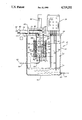
- a vessel provided with a mixing assembly comprised of co-axially and vertically-disposed inner and outer cylindrically-shaped wall members mounted to a bottom wall member wherein the inner wall member defines a mixing chamber and is provided with orifices about a lower portion thereof to provide fluid communication to a solution chamber defined between the wall members and wherein an upper end portion of the outer wall member defines a weir to the vessel and wherein an agitator is positioned within the mixing chamber to admix feed hydrophilic polymer and solvent in a vortex of polymeric solution contained in the mixing chamber and to cause the polymeric solution to overflow the weir into the vessel.
- a vessel 10 formed of a cylindrically-shaped side wall 12 and a bottom 14 and defining a chamber 16 and a mixing assembly of the present invention, generally indicated as 18.
- a solution outlet line 20 under the control of valve 22 is disposed in a lower portion of the cylindrically-shaped side wall 12.
- a platform member 24 for mounting a control panel assembly, generally indicated as 26, having a plurality of process level control electrodes 28, 30, 32 and 34 extending vertically downward into the chamber 16.
- the process level control electrodes 28, 30, 32 and 34 are connected to the control panel assembly 26 to provide a ground, process stop, process start and process alarm information, respectively.
- the process level control electrode 30 senses a full level (L 1 ) of polymeric solution wherein the process level control electrode 32 senses a lower level (L 2 ) at which level processing of the polymeric solution should be initiated to fulfill downstream process requirements.
- the process level control electrode 34 senses a level (L 3 ) of polymeric solution to alert process personnel to an upset condition.
- a cylindrically-shaped wall member 36 extending vertically downwardly into the chamber 16 of the vessel 10 and defining a mixing chamber 38.
- a cylindrically-shaped outer wall member 40 mounted to the cylindrically-shaped wall member 36 by radially and horizontally disposed spacer members 42 and defining an outer chamber 44.
- the lower portion of the cylindrically-shaped outer wall member 40 is enclosed by a bottom wall member 46 having a centrally-disposed fitting 48 for receiving a conduit 50 in fluid flow communication with line 52 under the control of valve 54.
- the upper portion of the cylindrically-shaped outer wall member 40 extends upwardly defining an overflow portion or weir 56 at a point above the level (L 1 ) of the polymeric solution in the vessel 10.
- the lower portion of the cylindrically-shaped inner wall member 36 proximate the bottom wall member 46 is formed with a plurality of vertically-extending slots 58 permitting fluid communication between the mixing chamber 38 and the outer chamber 44, as more fully hereinafter discussed.
- a support bridge Positioned on the platform member 24 is a support bridge, generally indicated as 60. On the support bridge 60, there is mounted a motor 62 having a vertically-disposed shaft 64 extending downwardly into the mixing chamber 38 in co-axial alignment therewith. A lower portion of the shaft 64 opposite the motor 62 is provided with an agitator member 66 positioned within the mixing chamber 38.
- a conduit 68 is provided in fluid flow communication with a source of solvent (not shown) by line 70 under the control of a solenoid valve 72.
- the conduit 68 is provided with an outlet 74 disposed above the mixing chamber 38.
- a conduit 76 is provided in fluid flow communication by line 78 with the discharge side of a metering pump 80.
- the suction side of the metering pump 80 is in fluid flow communication by line 82 with a source of the polymer (not shown).
- the conduit 76 is provided with an outlet 84 also disposed above the mixing chamber 38.
- the level of liquid in the outer chamber 44 rises until a point is reached whereby the liquid flows or spills over the weir 56 into the chamber 16 of the vessel 10.
- the flow of the liquids into the mixing chamber 38 is continued until a level of liquid (L 2 ) is reached in the chamber 16 of the vessel 10 as sensed by the process level control electrode 30 whereupon appropriate signals are generated to de-energize the metering pump 80 and close the solenoid valve 72 in line 70.
- the agitator member 66 continuously effects vigorous mixing of the polymer and solvent into the polymeric solution in the mixing chamber 38.
- the volume of the vessel 10 is chosen with respect to process requirements to provide an aging period for the polymeric solution i.e. uncoiling the hydrophilic polymer, and thereby to provide an aged polymeric solution for process requirements withdrawn by conduit 20 although it is understood that not all hydrophilic polymers will undergo an uncoiling process.
- a vessel having a capacity of about 300 gallons is provided with the mixing assembly comprised of the concentrically-mounted inner and outer wall members enclosed by the bottom wall member with slots formed in the lower portion of the inner wall member.
- a metering pump having a capacity of 0.01 to 0.1 gpm is provided in line 82.
- Polyacrylamide/55% inverted emulsion product (a typical hydrophilic polymer) is introduced into the mixing chamber 38 at a rate of 0.04 gpm and with water being introduced by the conduit 76 at a rate of 7.96 gpm to form a polymeric solution of a concentration of 0.5%. At this rate of introduction, 8.0 gallons per minute of the polymeric solution are formed.
- the motor 62 is preferably energized for about 60 seconds following the termination of liquid flow into the initial mixing chamber 38 to insure complete mixing.
Landscapes
- Chemical & Material Sciences (AREA)
- Chemical Kinetics & Catalysis (AREA)
- Processes Of Treating Macromolecular Substances (AREA)
- Processing And Handling Of Plastics And Other Materials For Molding In General (AREA)
Abstract
Description
Claims (4)
Priority Applications (2)
| Application Number | Priority Date | Filing Date | Title |
|---|---|---|---|
| US06/889,119 US4719252A (en) | 1986-07-22 | 1986-07-22 | Process and apparatus for forming polymeric solutions |
| EP87305755A EP0257743A1 (en) | 1986-07-22 | 1987-06-29 | Process and apparatus for forming polymeric solutions |
Applications Claiming Priority (1)
| Application Number | Priority Date | Filing Date | Title |
|---|---|---|---|
| US06/889,119 US4719252A (en) | 1986-07-22 | 1986-07-22 | Process and apparatus for forming polymeric solutions |
Publications (1)
| Publication Number | Publication Date |
|---|---|
| US4719252A true US4719252A (en) | 1988-01-12 |
Family
ID=25394537
Family Applications (1)
| Application Number | Title | Priority Date | Filing Date |
|---|---|---|---|
| US06/889,119 Expired - Fee Related US4719252A (en) | 1986-07-22 | 1986-07-22 | Process and apparatus for forming polymeric solutions |
Country Status (2)
| Country | Link |
|---|---|
| US (1) | US4719252A (en) |
| EP (1) | EP0257743A1 (en) |
Cited By (25)
| Publication number | Priority date | Publication date | Assignee | Title |
|---|---|---|---|---|
| WO1994006549A1 (en) * | 1992-09-18 | 1994-03-31 | Stranco, Inc. | Dry polymer activation apparatus and method |
| EP0671203A1 (en) * | 1994-03-08 | 1995-09-13 | Agfa-Gevaert N.V. | Photographic preparation device |
| US6409926B1 (en) | 1999-03-02 | 2002-06-25 | United States Filter Corporation | Air and water purification using continuous breakpoint halogenation and peroxygenation |
| US6419817B1 (en) | 2000-06-22 | 2002-07-16 | United States Filter Corporation | Dynamic optimization of chemical additives in a water treatment system |
| US6423234B1 (en) | 1999-03-02 | 2002-07-23 | United States Filter Corporation | Air and water purification using continuous breakpoint halogenation |
| US20030038277A1 (en) * | 2001-08-09 | 2003-02-27 | Roy Martin | Calcium hypochlorite of reduced reactivity |
| US20030160005A1 (en) * | 2002-02-26 | 2003-08-28 | Roy Martin | Enhanced air and water purification using continuous breakpoint halogenation with free oxygen radicals |
| US20030160004A1 (en) * | 2002-02-26 | 2003-08-28 | Roy Martin | Free radical generator and method |
| US6620315B2 (en) | 2001-02-09 | 2003-09-16 | United States Filter Corporation | System for optimized control of multiple oxidizer feedstreams |
| US6645400B2 (en) | 2000-06-22 | 2003-11-11 | United States Filter Corporation | Corrosion control utilizing a hydrogen peroxide donor |
| US6716359B1 (en) | 2000-08-29 | 2004-04-06 | United States Filter Corporation | Enhanced time-based proportional control |
| US20080245738A1 (en) * | 2007-04-03 | 2008-10-09 | Siemens Water Technologies Corp. | Method and system for providing ultrapure water |
| US20110024365A1 (en) * | 2009-07-30 | 2011-02-03 | Zhee Min Jimmy Yong | Baffle plates for an ultraviolet reactor |
| US20110180485A1 (en) * | 2006-06-06 | 2011-07-28 | Fluid Lines | Ultraviolet light activated oxidation process for the reduction of organic carbon in semiconductor process water |
| US20110210077A1 (en) * | 2007-04-03 | 2011-09-01 | Siemens Water Technologies Corp. | Method and system for providing ultrapure water |
| US20110209530A1 (en) * | 2007-04-03 | 2011-09-01 | Siemens Water Technologies Corp. | Method for measuring a concentration of a compound in a liquid stream |
| US20110210048A1 (en) * | 2007-04-03 | 2011-09-01 | Siemens Water Technologies Corp. | System for controlling introduction of a reducing agent to a liquid stream |
| US20110210267A1 (en) * | 2007-04-03 | 2011-09-01 | Siemens Water Technologies Corp. | Actinic radiation reactor |
| US20110210266A1 (en) * | 2007-04-03 | 2011-09-01 | Siemens Water Technologies Corp. | Method of irradiating a liquid |
| US8877067B2 (en) | 2011-05-26 | 2014-11-04 | Evoqua Water Technologies Llc | Method and arrangement for a water treatment |
| US9725343B2 (en) | 2007-04-03 | 2017-08-08 | Evoqua Water Technologies Llc | System and method for measuring and treating a liquid stream |
| US10343939B2 (en) | 2006-06-06 | 2019-07-09 | Evoqua Water Technologies Llc | Ultraviolet light activated oxidation process for the reduction of organic carbon in semiconductor process water |
| US10494281B2 (en) | 2015-01-21 | 2019-12-03 | Evoqua Water Technologies Llc | Advanced oxidation process for ex-situ groundwater remediation |
| EP3626336A1 (en) * | 2018-09-21 | 2020-03-25 | Savio Srl | Mixing system for the introduction of chemical substances in a fluid to be treated |
| US11161762B2 (en) | 2015-01-21 | 2021-11-02 | Evoqua Water Technologies Llc | Advanced oxidation process for ex-situ groundwater remediation |
Families Citing this family (2)
| Publication number | Priority date | Publication date | Assignee | Title |
|---|---|---|---|---|
| CA2114294A1 (en) * | 1993-01-05 | 1995-07-27 | Thomas Earle Allen | Apparatus and method for continuously mixing fluids |
| DE4309065C2 (en) * | 1993-03-20 | 1996-06-13 | Pluto Chem Betriebe | Dosing system |
Citations (2)
| Publication number | Priority date | Publication date | Assignee | Title |
|---|---|---|---|---|
| US3141656A (en) * | 1960-02-17 | 1964-07-21 | American Enka Corp | Viscose dissolver |
| US4420572A (en) * | 1980-12-19 | 1983-12-13 | Hoechst Aktiengesellschaft | Continuous process for the production of highly concentrated spinning solutions of acrylonitrile polymers and a suitable device for this purpose |
Family Cites Families (5)
| Publication number | Priority date | Publication date | Assignee | Title |
|---|---|---|---|---|
| US1928008A (en) * | 1931-12-21 | 1933-09-26 | Retsof Mining Company | Salt dissolving apparatus |
| FR1013177A (en) * | 1949-04-22 | 1952-07-23 | Potassium Chloride Dissolver | |
| FR1050637A (en) * | 1952-02-08 | 1954-01-08 | Houilleres Bassin Du Nord | Reactor for continuous work |
| US3607105A (en) * | 1969-08-22 | 1971-09-21 | Nalco Chemical Co | Automatic solvent aspirated powder feeder-dissolver |
| GB1510783A (en) * | 1975-04-16 | 1978-05-17 | British Industrial Plastics | Mixing |
-
1986
- 1986-07-22 US US06/889,119 patent/US4719252A/en not_active Expired - Fee Related
-
1987
- 1987-06-29 EP EP87305755A patent/EP0257743A1/en not_active Withdrawn
Patent Citations (2)
| Publication number | Priority date | Publication date | Assignee | Title |
|---|---|---|---|---|
| US3141656A (en) * | 1960-02-17 | 1964-07-21 | American Enka Corp | Viscose dissolver |
| US4420572A (en) * | 1980-12-19 | 1983-12-13 | Hoechst Aktiengesellschaft | Continuous process for the production of highly concentrated spinning solutions of acrylonitrile polymers and a suitable device for this purpose |
Cited By (42)
| Publication number | Priority date | Publication date | Assignee | Title |
|---|---|---|---|---|
| US5338779A (en) * | 1992-09-18 | 1994-08-16 | Stranco, Inc | Dry polymer activation apparatus and method |
| WO1994006549A1 (en) * | 1992-09-18 | 1994-03-31 | Stranco, Inc. | Dry polymer activation apparatus and method |
| EP0671203A1 (en) * | 1994-03-08 | 1995-09-13 | Agfa-Gevaert N.V. | Photographic preparation device |
| US6409926B1 (en) | 1999-03-02 | 2002-06-25 | United States Filter Corporation | Air and water purification using continuous breakpoint halogenation and peroxygenation |
| US6423234B1 (en) | 1999-03-02 | 2002-07-23 | United States Filter Corporation | Air and water purification using continuous breakpoint halogenation |
| US6645400B2 (en) | 2000-06-22 | 2003-11-11 | United States Filter Corporation | Corrosion control utilizing a hydrogen peroxide donor |
| US6419817B1 (en) | 2000-06-22 | 2002-07-16 | United States Filter Corporation | Dynamic optimization of chemical additives in a water treatment system |
| US6716359B1 (en) | 2000-08-29 | 2004-04-06 | United States Filter Corporation | Enhanced time-based proportional control |
| US6623647B2 (en) | 2001-02-09 | 2003-09-23 | United States Filter Corporation | Methods of optimized control of multiple oxidizer feedstreams |
| US6620315B2 (en) | 2001-02-09 | 2003-09-16 | United States Filter Corporation | System for optimized control of multiple oxidizer feedstreams |
| US6776926B2 (en) | 2001-08-09 | 2004-08-17 | United States Filter Corporation | Calcium hypochlorite of reduced reactivity |
| US20030038277A1 (en) * | 2001-08-09 | 2003-02-27 | Roy Martin | Calcium hypochlorite of reduced reactivity |
| US20040224088A1 (en) * | 2001-08-09 | 2004-11-11 | United States Filter Corporation | Calcium hypochlorite of reduced reactivity |
| US20050109709A1 (en) * | 2002-02-26 | 2005-05-26 | Usfilter Corporation | Enhanced air and water purification using continuous breakpoint halogenation with free oxygen radicals |
| US20030160005A1 (en) * | 2002-02-26 | 2003-08-28 | Roy Martin | Enhanced air and water purification using continuous breakpoint halogenation with free oxygen radicals |
| US20030160004A1 (en) * | 2002-02-26 | 2003-08-28 | Roy Martin | Free radical generator and method |
| US6991735B2 (en) | 2002-02-26 | 2006-01-31 | Usfilter Corporation | Free radical generator and method |
| US7108781B2 (en) | 2002-02-26 | 2006-09-19 | Usfilter Corporation | Enhanced air and water purification using continuous breakpoint halogenation with free oxygen radicals |
| US7285223B2 (en) | 2002-02-26 | 2007-10-23 | Siemens Water Technologies Holding Corp. | Enhanced air and water purification using continuous breakpoint halogenation with free oxygen radicals |
| US10550020B2 (en) | 2006-06-06 | 2020-02-04 | Evoqua Water Technologies Llc | Ultraviolet light activated oxidation process for the reduction of organic carbon in semiconductor process water |
| US10343939B2 (en) | 2006-06-06 | 2019-07-09 | Evoqua Water Technologies Llc | Ultraviolet light activated oxidation process for the reduction of organic carbon in semiconductor process water |
| US20110180485A1 (en) * | 2006-06-06 | 2011-07-28 | Fluid Lines | Ultraviolet light activated oxidation process for the reduction of organic carbon in semiconductor process water |
| US8652336B2 (en) | 2006-06-06 | 2014-02-18 | Siemens Water Technologies Llc | Ultraviolet light activated oxidation process for the reduction of organic carbon in semiconductor process water |
| US8753522B2 (en) | 2007-04-03 | 2014-06-17 | Evoqua Water Technologies Llc | System for controlling introduction of a reducing agent to a liquid stream |
| US8961798B2 (en) | 2007-04-03 | 2015-02-24 | Evoqua Water Technologies Llc | Method for measuring a concentration of a compound in a liquid stream |
| US20110210267A1 (en) * | 2007-04-03 | 2011-09-01 | Siemens Water Technologies Corp. | Actinic radiation reactor |
| US20110210266A1 (en) * | 2007-04-03 | 2011-09-01 | Siemens Water Technologies Corp. | Method of irradiating a liquid |
| US20080245738A1 (en) * | 2007-04-03 | 2008-10-09 | Siemens Water Technologies Corp. | Method and system for providing ultrapure water |
| US20110209530A1 (en) * | 2007-04-03 | 2011-09-01 | Siemens Water Technologies Corp. | Method for measuring a concentration of a compound in a liquid stream |
| US8741155B2 (en) | 2007-04-03 | 2014-06-03 | Evoqua Water Technologies Llc | Method and system for providing ultrapure water |
| US20110210077A1 (en) * | 2007-04-03 | 2011-09-01 | Siemens Water Technologies Corp. | Method and system for providing ultrapure water |
| US9764968B2 (en) | 2007-04-03 | 2017-09-19 | Evoqua Water Technologies Llc | Method and system for providing ultrapure water |
| US20110210048A1 (en) * | 2007-04-03 | 2011-09-01 | Siemens Water Technologies Corp. | System for controlling introduction of a reducing agent to a liquid stream |
| US9365435B2 (en) | 2007-04-03 | 2016-06-14 | Evoqua Water Technologies Llc | Actinic radiation reactor |
| US9365436B2 (en) | 2007-04-03 | 2016-06-14 | Evoqua Water Technologies Llc | Method of irradiating a liquid |
| US9725343B2 (en) | 2007-04-03 | 2017-08-08 | Evoqua Water Technologies Llc | System and method for measuring and treating a liquid stream |
| US20110024365A1 (en) * | 2009-07-30 | 2011-02-03 | Zhee Min Jimmy Yong | Baffle plates for an ultraviolet reactor |
| US8591730B2 (en) | 2009-07-30 | 2013-11-26 | Siemens Pte. Ltd. | Baffle plates for an ultraviolet reactor |
| US8877067B2 (en) | 2011-05-26 | 2014-11-04 | Evoqua Water Technologies Llc | Method and arrangement for a water treatment |
| US10494281B2 (en) | 2015-01-21 | 2019-12-03 | Evoqua Water Technologies Llc | Advanced oxidation process for ex-situ groundwater remediation |
| US11161762B2 (en) | 2015-01-21 | 2021-11-02 | Evoqua Water Technologies Llc | Advanced oxidation process for ex-situ groundwater remediation |
| EP3626336A1 (en) * | 2018-09-21 | 2020-03-25 | Savio Srl | Mixing system for the introduction of chemical substances in a fluid to be treated |
Also Published As
| Publication number | Publication date |
|---|---|
| EP0257743A1 (en) | 1988-03-02 |
Similar Documents
| Publication | Publication Date | Title |
|---|---|---|
| US4719252A (en) | Process and apparatus for forming polymeric solutions | |
| US4054514A (en) | Sedimentation apparatus with flocculating feed well | |
| US4217145A (en) | Process for admixing polymer emulsions with water to produce highly viscous liquids | |
| US2695710A (en) | Flotation and clarification apparatus | |
| US3782695A (en) | Apparatus and method for dispersing solid particles in a liquid | |
| AU2010315785B2 (en) | Method of optimizing feed concentration in a sedimentation vessel | |
| GB1247728A (en) | Method and apparatus for separation of solids from liquids | |
| US4246111A (en) | Apparatus for biological treatment of waste water | |
| US4957708A (en) | Process and apparatus for forming polymeric solutions | |
| EP0028093B1 (en) | Method and apparatus for the separation of gas and solids from waste mixed liquors | |
| US2138349A (en) | Method and apparatus for aerating sewage | |
| CN217025454U (en) | Mechanical stirring clarification tank circulating slurry monitoring device | |
| US4452701A (en) | Biological treatment of sewage | |
| CN112573653A (en) | Internal circulation anaerobic reaction system with denitrification function | |
| JP2628163B2 (en) | Method for activating polymer, method for continuously producing activated emulsion polymer at a variable rate, and apparatus therefor | |
| US3329407A (en) | Aeration | |
| JPS643555B2 (en) | ||
| GB679635A (en) | Improvements in or relating to an apparatus and process for treating polluted liquid | |
| US3438890A (en) | Method and apparatus for separating solids-liquids mixtures | |
| CA1051132A (en) | Sedimentation apparatus with flocculating feed well | |
| JPH09290280A (en) | Ozone contact tank and control method therefor | |
| US2742422A (en) | Apparatus for resolving highly stable suspensions | |
| US4652364A (en) | Apparatus for adjusting the concentration of a solution | |
| US3287263A (en) | Method of and apparatus for controlling addition of reagents to the feed of phase separation vessels | |
| US7160394B2 (en) | Sugar juice clarifier apparatus |
Legal Events
| Date | Code | Title | Description |
|---|---|---|---|
| AS | Assignment |
Owner name: DREW CHEMICAL CORPORATION, ONE DREW CHEMICAL PLAZA Free format text: ASSIGNMENT OF ASSIGNORS INTEREST.;ASSIGNORS:DUTTON, JAMES P.;BEECH, RONALD;REEL/FRAME:004609/0224 Effective date: 19860908 Owner name: DREW CHEMICAL CORPORATION, ONE DREW CHEMICAL PLAZA Free format text: ASSIGNMENT OF ASSIGNORS INTEREST;ASSIGNORS:DUTTON, JAMES P.;BEECH, RONALD;REEL/FRAME:004609/0224 Effective date: 19860908 |
|
| FEPP | Fee payment procedure |
Free format text: PAYOR NUMBER ASSIGNED (ORIGINAL EVENT CODE: ASPN); ENTITY STATUS OF PATENT OWNER: LARGE ENTITY |
|
| FPAY | Fee payment |
Year of fee payment: 4 |
|
| AS | Assignment |
Owner name: ASHLAND INC. (A KENTUCKY CORPORATION), KENTUCKY Free format text: CHANGE OF NAME;ASSIGNOR:ASHLAND OIL, INC. (A KENTUCKY CORPORATION);REEL/FRAME:007378/0147 Effective date: 19950127 |
|
| REMI | Maintenance fee reminder mailed | ||
| LAPS | Lapse for failure to pay maintenance fees | ||
| FP | Lapsed due to failure to pay maintenance fee |
Effective date: 19960117 |
|
| STCH | Information on status: patent discontinuation |
Free format text: PATENT EXPIRED DUE TO NONPAYMENT OF MAINTENANCE FEES UNDER 37 CFR 1.362 |