US4713181A - Method and apparatus for handling sludge - Google Patents
Method and apparatus for handling sludge Download PDFInfo
- Publication number
- US4713181A US4713181A US06/841,078 US84107886A US4713181A US 4713181 A US4713181 A US 4713181A US 84107886 A US84107886 A US 84107886A US 4713181 A US4713181 A US 4713181A
- Authority
- US
- United States
- Prior art keywords
- sludge
- water
- wet
- paint sludge
- screen
- Prior art date
- Legal status (The legal status is an assumption and is not a legal conclusion. Google has not performed a legal analysis and makes no representation as to the accuracy of the status listed.)
- Expired - Fee Related
Links
- 239000010802 sludge Substances 0.000 title claims abstract description 172
- 238000000034 method Methods 0.000 title claims abstract description 16
- XLYOFNOQVPJJNP-UHFFFAOYSA-N water Substances O XLYOFNOQVPJJNP-UHFFFAOYSA-N 0.000 claims abstract description 74
- 230000009471 action Effects 0.000 claims abstract description 8
- 239000003973 paint Substances 0.000 claims description 38
- 238000007599 discharging Methods 0.000 claims 3
- 239000000463 material Substances 0.000 abstract description 6
- 239000007787 solid Substances 0.000 abstract description 5
- 239000000725 suspension Substances 0.000 abstract description 4
- 239000002245 particle Substances 0.000 description 11
- 238000000926 separation method Methods 0.000 description 10
- 239000007788 liquid Substances 0.000 description 9
- 239000007921 spray Substances 0.000 description 6
- 230000008569 process Effects 0.000 description 5
- 238000005054 agglomeration Methods 0.000 description 4
- 230000002776 aggregation Effects 0.000 description 4
- 239000003570 air Substances 0.000 description 4
- 230000010355 oscillation Effects 0.000 description 4
- 229920000867 polyelectrolyte Polymers 0.000 description 4
- 239000000126 substance Substances 0.000 description 4
- 230000002209 hydrophobic effect Effects 0.000 description 3
- 238000012423 maintenance Methods 0.000 description 3
- 239000000047 product Substances 0.000 description 3
- 239000004677 Nylon Substances 0.000 description 2
- 229910000278 bentonite Inorganic materials 0.000 description 2
- 239000000440 bentonite Substances 0.000 description 2
- SVPXDRXYRYOSEX-UHFFFAOYSA-N bentoquatam Chemical compound O.O=[Si]=O.O=[Al]O[Al]=O SVPXDRXYRYOSEX-UHFFFAOYSA-N 0.000 description 2
- 239000004927 clay Substances 0.000 description 2
- 230000001419 dependent effect Effects 0.000 description 2
- 239000012530 fluid Substances 0.000 description 2
- 229920001778 nylon Polymers 0.000 description 2
- 238000004064 recycling Methods 0.000 description 2
- 230000000284 resting effect Effects 0.000 description 2
- 230000035939 shock Effects 0.000 description 2
- 230000001360 synchronised effect Effects 0.000 description 2
- 238000005273 aeration Methods 0.000 description 1
- 239000011324 bead Substances 0.000 description 1
- 239000006227 byproduct Substances 0.000 description 1
- 230000008859 change Effects 0.000 description 1
- 238000010924 continuous production Methods 0.000 description 1
- 210000003298 dental enamel Anatomy 0.000 description 1
- 238000006073 displacement reaction Methods 0.000 description 1
- -1 enamel Substances 0.000 description 1
- 230000007613 environmental effect Effects 0.000 description 1
- 210000000416 exudates and transudate Anatomy 0.000 description 1
- 238000007429 general method Methods 0.000 description 1
- 239000004922 lacquer Substances 0.000 description 1
- 230000007246 mechanism Effects 0.000 description 1
- 239000002184 metal Substances 0.000 description 1
- 238000012986 modification Methods 0.000 description 1
- 230000004048 modification Effects 0.000 description 1
- 230000000630 rising effect Effects 0.000 description 1
- 238000005096 rolling process Methods 0.000 description 1
- 239000010865 sewage Substances 0.000 description 1
- 239000011343 solid material Substances 0.000 description 1
- 238000003860 storage Methods 0.000 description 1
- 238000012360 testing method Methods 0.000 description 1
Images

Classifications
-
- B—PERFORMING OPERATIONS; TRANSPORTING
- B01—PHYSICAL OR CHEMICAL PROCESSES OR APPARATUS IN GENERAL
- B01D—SEPARATION
- B01D21/00—Separation of suspended solid particles from liquids by sedimentation
- B01D21/0012—Settling tanks making use of filters, e.g. by floating layers of particulate material
-
- B—PERFORMING OPERATIONS; TRANSPORTING
- B01—PHYSICAL OR CHEMICAL PROCESSES OR APPARATUS IN GENERAL
- B01D—SEPARATION
- B01D21/00—Separation of suspended solid particles from liquids by sedimentation
- B01D21/02—Settling tanks with single outlets for the separated liquid
-
- B—PERFORMING OPERATIONS; TRANSPORTING
- B01—PHYSICAL OR CHEMICAL PROCESSES OR APPARATUS IN GENERAL
- B01D—SEPARATION
- B01D21/00—Separation of suspended solid particles from liquids by sedimentation
- B01D21/24—Feed or discharge mechanisms for settling tanks
- B01D21/2433—Discharge mechanisms for floating particles
-
- B—PERFORMING OPERATIONS; TRANSPORTING
- B01—PHYSICAL OR CHEMICAL PROCESSES OR APPARATUS IN GENERAL
- B01D—SEPARATION
- B01D35/00—Filtering devices having features not specifically covered by groups B01D24/00 - B01D33/00, or for applications not specifically covered by groups B01D24/00 - B01D33/00; Auxiliary devices for filtration; Filter housing constructions
- B01D35/20—Vibrating the filters
-
- B—PERFORMING OPERATIONS; TRANSPORTING
- B01—PHYSICAL OR CHEMICAL PROCESSES OR APPARATUS IN GENERAL
- B01D—SEPARATION
- B01D35/00—Filtering devices having features not specifically covered by groups B01D24/00 - B01D33/00, or for applications not specifically covered by groups B01D24/00 - B01D33/00; Auxiliary devices for filtration; Filter housing constructions
- B01D35/28—Strainers not provided for elsewhere
Definitions
- the present invention relates to a method and apparatus for handling sludge precipitated during, e.g., water, sewage or air treatment processes and the like.
- This patent discloses the use of a separate tank to which sludge-laden water is conducted for removal of sludge and aeration of the water before the water is returned to the reservoir for recycling in the water wash or is otherwise disposed of.
- the sludge is urged to the surface of the tank through water circulation means, and is then skimmed off the surface of the water into a collection bin for recycling, disposal, etc.
- the water and sludge are conveyed to a vacuum-type filter with the water and sludge being deposited on the top of a screen with a vacuum being applied under the screen to pull the water through the screen.
- the sludge is left on top of the screen.
- This system has a tendency to have the sludge clog the screens and is a high maintenance system. It will be appreciated that a very high volume of water to sludge is being conveyed to the screens and this water and the vacuum tend to cause the sludge to enter into and clog the screen holes.
- Another continuous process in which a high volume flow of water from the spray tank reservoir is used to convey the sludge particles is a centrifuge system in which the liquid and sludge particles are introduced into the top of the centerfuge and spun downwardly with the water being thrown off and with the sludge exiting through a bottom orifice.
- the sludge has a tendency to clog the centerfuge orifice and this also results in high maintenance problems. It will be appreciated that the sludge is a very cohesive and sticky material and may clog such orifices.
- Dried sludge is sludge that has been dewatered so that it can be transported and handled as a solid material, while liquid sludge is readily pumpable and must be transported by a closed vessel which will not allow any leakage or spillage.
- Dewatered sludge may be transported in open dump trucks. Further, neither containers holding free liquids nor noncontainerized liquid sludge may be placed in a landfill unless the landfill has an impermeable liner and leachate collection means. Consequently, greater safety and convenience can be obtained if the sludge is dewatered before disposal. Tests for classification of sludge are available from governmental agencies such as Environmental Protection Agencies.
- a still further object is to provide a method and apparatus that provides for the collection of both the solid sludge and liquid dewatered therefrom.
- skimmed sludge is still too wet to be classified as "dried sludge” under most govermental standards so that it needs to be further dewatered before it can be classified as “dried sludge”; and to this end, the skimmed sludge is conveyed by conveying means to a sludge dewatering means which removes sufficient water from the skim sludge to have it classified as “dried sludge.”
- the preferred dewatering means oscillates the sludge or produces a squeezing action on the sludge on a screen to exude the occluded water.
- the preferred screen is inclined and oscillated or vibrated to work the sludge downwardly while exuding water therefrom.
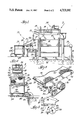
- FIG. 1 is a side elevation of an apparatus embodying the present invention in conjunction with a sludge skimming apparatus for initially separating sludge from the water;
- FIG. 2 is an end elevation of the device of FIG. 1;
- FIG. 3 is an enlarged perspective view of the inclined oscillating sieve means
- FIG. 4 is an enlarged fragmentary side elevation of the sieve oscillating means
- FIG. 5 is a side elevation of an alternate embodiment embodying the instant invention, once again in conjunction with a sludge skimming apparatus;
- FIG. 6 is an end elevation of the device of FIG. 5.
- FIG. 7 is an enlarged cross-sectional view of the sieve oscillating means of the device of FIGS. 5 and 6.
- a sludge dewatering apparatus shown in conjunction with a sludge separation device 11, for initially removing supernatent sludge from the water that is used, e.g., in a water wash for entraining overspray particles in a spray booth.
- the sludge separation device 11 is preferably as described in U.S. Pat. No. 4,432,870, or in my copending application Ser. No. 688,571, filed Jan. 3, 1985, both having a common assignee and being herein incorporated by reference.
- the device 11 includes a separation tank 12 which receives a supply of liquid-sludge suspension from an adjacent holding tank or reservoir 13 of a spray booth, only, a booth wall 14 and the booth reservoir being illustrated herein.
- the water-sludge suspension is pumped through a conduit 14 having an outlet at the bottom of the separation tank 12.
- the reservoir 13 is associated with, e.g., a water wash for a spray booth (not shown) in which the airborne overspray particles in the booth are drawn into a water curtain which entrains the particles prior to flowing into the reservoir 13. Sludge and water from the reservoir 13 are pumped into the separation tank 12 and the sludge is circulated upwardly toward the surface of the water in the tank 12.
- An automatic skimming device 15 includes a motor-driven carriage 16 mounted for movement on top of the separation tank 12.
- a pusher plate 18 secured to the carriage 16 engages the supernatent sludge 19 and drives the sludge 19 up and off a ramp 20 and onto a dewatering apparatus, generally indicated by 10, from which it goes into a collection drum 22.
- Both the clarified water remaining in the separation tank 12 and the water occluded during the dewatering process are returned to the reservoir 13 where it is reused in the water wash or otherwise treated to facilitate its disposal.
- the paint sludge is comprised of the paint particles which have been agglomerated.
- the water in the reservoir is treated with agglomerating chemicals in a well-known manner to which cause the paint particles to stick together to form floating sludge pieces. These chemicals also assist in causing the density of the paint sludge to be less than that of the water so as to float on the water.
- the agglomeration results in a sticky or tacky sludge which adheres to surfaces and which tends to plug holes in screens.
- the paint sludge is hydrophylic and has substantial quantities of water clinging thereto so that skimming from a body of liquid the sludge will be classified as a wet sludge.
- a chemical such as, for example, a bentonite clay is injected into water in the reservoir to reduce very substantially the tackiness of sludge while not substantially destroying the agglomeration characteristics of the paint particles to adhere to one another.
- the sludge is treated to change its hydrophylic character to a hydrophobic character to aid in a later dewatering of the wet skimmed sludge. This is achieved in this illustrated embodiment of the invention by injecting a polyelectrolyte material into the sludge bearing water by an injector 17 (FIG. 1) through a pipe 21 into the pipe 14 conveying the water from the reservoir 13 to the skimmer tank.
- Polyelectrolyte materials are well known and commercially available.
- the polyelectrolyte mixes gently because of the turbulence caused by the inlet pipe elbows and changes the state of the sludge from hydrophlic to hydrophobic so that the water tends to bead on the surface of the sludge and so that the water can be more readily separated mechanically from the solid paint particle agglomeration of the wet sludge.
- sludge dewatering means is provided to reduce the liquid content of the sludge prior to further handling, treatment or disposal of the sludge.
- the preferred dewatering means includes a sieve means which is disposed a predetermined distance below the edge of the ramp means 20 on the separation tank 12. Means are provided for causing the skimmed sludge to fall from the ramp 20 onto the sieve means, with the initial impact of the sludge falling onto the sieve causing the sludge to exude at least a portion of the water carried thereby and allowing it to pass through the sieve.
- Means is provided for vibrating or oscillating the sludge-supporting sieve so as to both cause further exudation of water from the sludge and to urge the sludge down the inclined surface of the sieve means toward a collection container 22.
- the amount of exudate is controlled by the angle of incline and length of the sieve means and by means for adjusting the frequency and amplitude of the oscillations of the sieve means, all of which combine to control the length of time that the sludge is on the sieve.
- the sludge dewatering apparatus 10 includes an open-top drainage trough 24 supported on a stand 25 and having a return or drainage pipe 26 extending between a lower portion of the trough 24 and the reservoir 13.
- Sieve means 28 is supported over the trough 24 a predetermined distance below the edge of the ramp 20 on the separation tank 12. The distance between the edge of the ramp 20 and the upper portion of the sieve means 28 may be several feet or less. This distance ensures that, while a large portion of the water carried by the sludge 19 will be exuded upon impact with the sieve means 28, the fragile nature of the sludge 19 is not interfered with and the sludge remains intact.
- the sieve means comprises an open box frame 29 carrying a perforated sheet 30 over its upper end.
- the perforated sheet 30 serves to support a screen 31 that is coextensive with the sheet 30.
- the screen support 30 and the screen 31 cooperate to permit water exuded from the sludge 19 to flow into the trough 24, while the maintaining the sludge on top of the sieve means 28.
- the screen support 30 is made of sheet metal having inch diameter perforations based at an interval of inches between centers, while the screen may be of nylon having a mesh size of
- the illustrated lifting and dropping means includes cam means 38 mounted on each end of an axle 39 journaled in the lower portion of the trough 24 so that the cam means 38 bear on each side member 34 of the screen frame 29.
- a variable speed motor 40 mounted on a stand 41 secured to the side of the trough 24 rotates the cam 38/axle 39 combination by means of a conventional belt-pulley arrangement 42.
- the lower end of the sieve 28 may include resilient shock absorbing pads 43 to prevent excessive wear on the sieve means 28.
- the action of the cam 38/axle 39 is best seen in FIG. 4.
- the cams 38 revolve to lift the sieve means 28 without shock, but to drop the sieve 28 rapidly back to its initial position.
- the intermittant slow rise of the sieve 28 and rapid fall with a sudden stop causes the heavier water to continue to fall relative to lighter polymeric paint sludge which is held against further dropping while the water continues to flow down through the sieve 28.
- the rising and falling action also changes the slope so that the sludge tends to slide down the screen to the lower end thereof.
- Means is provided for varying the extent of vertical displacement of the sieve 28 comprising a threaded screw member 46 on each cam 38.
- the screw 46 may be moved into or out of the disk portion 48 of each cam 38 to effectively shorten or lengthen the throw of the cam 38.
- the throw of the cam 38 (and consequently, the distance the sieve means 28 will be dropped) varies between 0.0 inches and 0.50 inches.
- the lowest point of the screen means 28 has a reduced angle portion defined by a lip 47 to cause a backup or agglomeration of sludge 19 at the lower end of the screen.
- the sludge 19 now substantially dewatered is squeezed on the lip 47 by the in-coming sludge to the lip to aid in dewatering the sludge.
- Sludge will continue to be pushed across the lip 47 to fall from the lower portion of the sieve 28 into the collection drum 22. Any remaining water exuded from the sludge 19 by falling into the drum 22 may be drained off into, e.g., the reservoir 13 by means of a hose 44 at the bottom of the drum 22. After the last of the water is drained through the hose 44, the drum may be sealed and rolled away on casters 45.
- the extent to which the sludge is dewatered is dependent upon the length of time the sludge remains on the screen while the sieve is oscillating. This, in turn, is dependent not only upon the magnitude and frequency of the oscillations, but also upon the length of the sieve and the angle of incline. It is contemplated that the sieve means 28 will be oscillated at a frequency of between 120 and 300 cycles per minute and that an angle of incline of between 25 and 35 degrees with a sieve length of between 2 feet and 0 inches and 3 feet and 0 inches will provide sufficient resident time for the sludge on the sieve to provide "dried" sludge for the purposes of sludge disposal.
- FIGS. 5-7 an alternate embodiment of a sludge dewatering apparatus is seen. While the sludge is still dewatered by an oscillating or vibrating action of an inclined sieve or screen means, the mechanism by which the screen means works the sludge is altered. However, the elements common to both illustrated embodiments are identified by identical reference numerals.
- the screen means 50 includes a flexible oscillating inclined screen 51 disposed a predetermined distance below the ramp 20 and shown with its longitudinal axis transverse to the sludge separator 11 and disposed over the trough 24, which catches occluded water to return the same to the reservoir 13 through the return pipe 26.
- the screen 51 which is preferably made of nylon having a mesh size of approximately 200 microns, has a U- or a V-shaped cross-section, with its upper portions secured to elongated rods 52, which are mounted for synchronized rotation on supports 54, 55 at either end thereof.
- the sludge falls into lowest part of the V and squeezes together to exude water because of the individual sludge pieces squeezing together in the V of the screen 51.
- FIG. 7 One manner of oscillating the screen 51 is shown in FIG. 7 and includes a fluid motor cylinder 56 which is connected to a suitable fluid pressure source to reciprocate a rod 56a which has an end pinned to a block 57 secured to a roller chain 58 mounted to turn about sprockets 58a.
- the sprockets 58a are each secured to one of the rods 52 to which are secured the respective ends of the screen 51.
- the block 57 is driven rectilinearly back and forth toward the respective sprockets causing the respective rods attached thereto to wind and then unwind the ends of the screen attached thereto.
- the screen is oscillated back and forth.
- a roller 61 is journaled on a shaft mounted on the support 55 to project into the shape of the flexible screen 51 during its oscillations.
- the synchronized oscillating motion creates a rolling action on the sludge and on the water clinging to the polymeric paint portion of the sludge causing the water to roll because of its heavier density than the polymeric solids relative to the solids and to drop therefrom.
- At the lower end of the screen 51 is an inclined lip 62 on which dewatered sludge 19 accumulates before dropping in the drum 22.
- the degree to which the sludge 19 is dewatered depends upon the magnitude and frequency of the oscillations (which may be controlled by the motor) and the length and angle of incline of the flexible screen. It is contemplated that for adequate sludge dewatering, the screen will wind and unwind about the rods 52 on the magnitude of to 4 inches at a frequency between 120 to 200 cycles per minute (i.e., one cycle constitutes one instance of the flexible screen 51 being wound about the elongated rods 52 and then unwound therefrom), while the longitudinal length of the screen is between 4 and 6 feet with the angle of incline of the screen being between 15 and 25 degrees.
- the general method of dewatering sludge is the same.
- the sludge after being initially separated from the water, by a skimming apparatus is then conveyed to a dewatering means to remove sufficient water therefrom to classify the sludge as "dried” rather than "wet" sludge.
- the preferred step of dewatering includes vibrating, oscillating or otherwise working the sludge so as to additionally exude water.
- the exuded water drops through a screen to be returned to a reservoir or otherwise disposed of.
- the sludge travels across the screen and then drops into a container for storage, etc.
- the sludge is changed from a generally hydrophilic state to a hydrophobic state by addition of a polyelectrolyte which polymerizes the paint particles.
- a polyelectrolyte which polymerizes the paint particles.
Abstract
Description
Claims (4)
Priority Applications (1)
| Application Number | Priority Date | Filing Date | Title |
|---|---|---|---|
| US06/841,078 US4713181A (en) | 1986-03-18 | 1986-03-18 | Method and apparatus for handling sludge |
Applications Claiming Priority (1)
| Application Number | Priority Date | Filing Date | Title |
|---|---|---|---|
| US06/841,078 US4713181A (en) | 1986-03-18 | 1986-03-18 | Method and apparatus for handling sludge |
Publications (1)
| Publication Number | Publication Date |
|---|---|
| US4713181A true US4713181A (en) | 1987-12-15 |
Family
ID=25283962
Family Applications (1)
| Application Number | Title | Priority Date | Filing Date |
|---|---|---|---|
| US06/841,078 Expired - Fee Related US4713181A (en) | 1986-03-18 | 1986-03-18 | Method and apparatus for handling sludge |
Country Status (1)
| Country | Link |
|---|---|
| US (1) | US4713181A (en) |
Cited By (11)
| Publication number | Priority date | Publication date | Assignee | Title |
|---|---|---|---|---|
| US5378376A (en) * | 1993-07-06 | 1995-01-03 | Wisconsin Oven Corporation | Sludge collector employing floating weir |
| US6273270B1 (en) * | 1998-08-25 | 2001-08-14 | Omega Co. Ltd. | Dam fed unrollable media filter subsequently folded along its length and rewound |
| US20040031739A1 (en) * | 2002-08-13 | 2004-02-19 | Miller James E. | Paint-sludge filtration system featuring pool aeration using high-pressure discharge from filter vacuum producer |
| US20070203006A1 (en) * | 2006-02-28 | 2007-08-30 | Hughes Tim P | Pressure pad for closing bottom of carton |
| US20080190834A1 (en) * | 2007-02-13 | 2008-08-14 | Urquhart Gordon T | Oil-sludge filtration system having a free floating weir box |
| US8277652B2 (en) | 2007-02-13 | 2012-10-02 | Urquhart Gordon T | Oil-sludge filtration system with aeration pump |
| WO2014176057A3 (en) * | 2013-04-22 | 2015-10-29 | Vette Paul | Dynamic dewatering system |
| CN110052214A (en) * | 2019-05-13 | 2019-07-26 | 北京国电龙源环保工程有限公司 | A kind of wet mud uniform distribution device |
| US10525380B2 (en) | 2016-01-12 | 2020-01-07 | Air And Liquid Systems, Inc. | Floating chopper sludge weir |
| US10653978B2 (en) * | 2017-12-18 | 2020-05-19 | Halliburton Energy Services, Inc. | Filtering skimmers and beaches for use in water separation and treatment |
| CN117209118A (en) * | 2023-03-28 | 2023-12-12 | 江苏格兰特干燥浓缩设备有限公司 | Sludge treatment process for spiral wringer |
Citations (5)
| Publication number | Priority date | Publication date | Assignee | Title |
|---|---|---|---|---|
| US2851163A (en) * | 1954-12-29 | 1958-09-09 | Sundstrand Machine Tool Co | Coolant filter |
| US3896030A (en) * | 1973-08-28 | 1975-07-22 | Albert Bahr | Filter press, particularly for dewatering sludge in sewage treatment plants |
| US4019431A (en) * | 1973-03-17 | 1977-04-26 | Alb. Klein Kg | Method of dewatering sludge |
| US4243527A (en) * | 1979-03-29 | 1981-01-06 | Martin Leonard | Particulate material separator and method |
| US4350591A (en) * | 1980-10-20 | 1982-09-21 | Lee Joseph E | Drilling mud cleaning apparatus |
-
1986
- 1986-03-18 US US06/841,078 patent/US4713181A/en not_active Expired - Fee Related
Patent Citations (5)
| Publication number | Priority date | Publication date | Assignee | Title |
|---|---|---|---|---|
| US2851163A (en) * | 1954-12-29 | 1958-09-09 | Sundstrand Machine Tool Co | Coolant filter |
| US4019431A (en) * | 1973-03-17 | 1977-04-26 | Alb. Klein Kg | Method of dewatering sludge |
| US3896030A (en) * | 1973-08-28 | 1975-07-22 | Albert Bahr | Filter press, particularly for dewatering sludge in sewage treatment plants |
| US4243527A (en) * | 1979-03-29 | 1981-01-06 | Martin Leonard | Particulate material separator and method |
| US4350591A (en) * | 1980-10-20 | 1982-09-21 | Lee Joseph E | Drilling mud cleaning apparatus |
Cited By (18)
| Publication number | Priority date | Publication date | Assignee | Title |
|---|---|---|---|---|
| US5378376A (en) * | 1993-07-06 | 1995-01-03 | Wisconsin Oven Corporation | Sludge collector employing floating weir |
| US6273270B1 (en) * | 1998-08-25 | 2001-08-14 | Omega Co. Ltd. | Dam fed unrollable media filter subsequently folded along its length and rewound |
| US20040031739A1 (en) * | 2002-08-13 | 2004-02-19 | Miller James E. | Paint-sludge filtration system featuring pool aeration using high-pressure discharge from filter vacuum producer |
| US6761820B2 (en) * | 2002-08-13 | 2004-07-13 | Air And Liquid Systems, Inc. | Paint-sludge filtration system featuring pool aeration using high-pressure discharge from filter vacuum producer |
| US20070203006A1 (en) * | 2006-02-28 | 2007-08-30 | Hughes Tim P | Pressure pad for closing bottom of carton |
| US7326163B2 (en) * | 2006-02-28 | 2008-02-05 | Evergreen Packaging Inc. | Pressure pad for closing bottom of carton |
| US8277652B2 (en) | 2007-02-13 | 2012-10-02 | Urquhart Gordon T | Oil-sludge filtration system with aeration pump |
| US7767085B2 (en) | 2007-02-13 | 2010-08-03 | Air And Liquid Systems, Inc. | Oil-sludge filtration system having a free floating weir box |
| US20080190834A1 (en) * | 2007-02-13 | 2008-08-14 | Urquhart Gordon T | Oil-sludge filtration system having a free floating weir box |
| WO2014176057A3 (en) * | 2013-04-22 | 2015-10-29 | Vette Paul | Dynamic dewatering system |
| CN105246842A (en) * | 2013-04-22 | 2016-01-13 | 保罗·维特 | Dynamic dewatering system |
| US10093570B2 (en) | 2013-04-22 | 2018-10-09 | Paul VETTE | Dynamic dewatering system |
| US10525380B2 (en) | 2016-01-12 | 2020-01-07 | Air And Liquid Systems, Inc. | Floating chopper sludge weir |
| US10653978B2 (en) * | 2017-12-18 | 2020-05-19 | Halliburton Energy Services, Inc. | Filtering skimmers and beaches for use in water separation and treatment |
| CN110052214A (en) * | 2019-05-13 | 2019-07-26 | 北京国电龙源环保工程有限公司 | A kind of wet mud uniform distribution device |
| CN110052214B (en) * | 2019-05-13 | 2024-03-22 | 国能龙源环保有限公司 | Uniform distribution device for wet sludge |
| CN117209118A (en) * | 2023-03-28 | 2023-12-12 | 江苏格兰特干燥浓缩设备有限公司 | Sludge treatment process for spiral wringer |
| CN117209118B (en) * | 2023-03-28 | 2024-03-08 | 江苏格兰特干燥浓缩设备有限公司 | Sludge treatment process for spiral wringer |
Similar Documents
| Publication | Publication Date | Title |
|---|---|---|
| US4713181A (en) | Method and apparatus for handling sludge | |
| US4844106A (en) | Apparatus and method for cleaning shards for recycling | |
| US3568839A (en) | Apparatus for separating and removing floatables | |
| DE2639197C2 (en) | ||
| US5372711A (en) | Two stage system for skimming floating particles | |
| US4255269A (en) | Method and apparatus for adapting the composition of a drilling fluid for use in making a hole in the earth by rotary drilling | |
| KR101729262B1 (en) | Adulteration disposal equipment with wedge bar screen | |
| JPH0784715B2 (en) | Pulp and stock concentrator | |
| US4285816A (en) | Dewatering system | |
| US3537584A (en) | Apparatus for removing solids from liquid suspensions thereof | |
| US5462673A (en) | Cleaning system for vibratory screening devices | |
| AU608612B2 (en) | Method and apparatus for separation using fluidized bed | |
| US3774760A (en) | Sludge dewatering apparatus and process | |
| US4886608A (en) | Apparatus and method for separating liquids and solids | |
| EP2021095A2 (en) | Belt filter apparatus | |
| US2070201A (en) | Process for dehydrating pulps | |
| US6976592B1 (en) | Liquid/solids waste separator | |
| US5202017A (en) | Continuous media filter with monitoring of liquid level in distributor | |
| US5569331A (en) | Method and apparatus for recycling oil-soaked boom and pads | |
| US4915850A (en) | Method and apparatus for separating granulate from a viscous suspension | |
| US4597865A (en) | Rotary liquid separation unit | |
| US4277339A (en) | Paint pigment skimmer | |
| JP4928438B2 (en) | Levitation separation apparatus and levitation separation method | |
| US3042208A (en) | Combined washer, separator and grader for loose materials | |
| US4247395A (en) | Sewage treatment process and apparatus |
Legal Events
| Date | Code | Title | Description |
|---|---|---|---|
| AS | Assignment |
Owner name: PROTECTAIRE SYSTEMS CO., 1440 HOLMES ROAD, ELGIN, Free format text: ASSIGNMENT OF ASSIGNORS INTEREST.;ASSIGNOR:RUSSELL, FREDERICK E.;REEL/FRAME:004550/0853 Effective date: 19860505 Owner name: PROTECTAIRE SYSTEMS CO., ILLINOIS Free format text: ASSIGNMENT OF ASSIGNORS INTEREST;ASSIGNOR:RUSSELL, FREDERICK E.;REEL/FRAME:004550/0853 Effective date: 19860505 |
|
| AS | Assignment |
Owner name: FIRST BANK OF SCHAUMBURG, ILLINOIS Free format text: SECURITY INTEREST;ASSIGNOR:PROTECTAIRE SYSTEMS CO.;REEL/FRAME:005029/0037 Effective date: 19881230 |
|
| FEPP | Fee payment procedure |
Free format text: PAYOR NUMBER ASSIGNED (ORIGINAL EVENT CODE: ASPN); ENTITY STATUS OF PATENT OWNER: SMALL ENTITY |
|
| REMI | Maintenance fee reminder mailed | ||
| FPAY | Fee payment |
Year of fee payment: 4 |
|
| SULP | Surcharge for late payment | ||
| AS | Assignment |
Owner name: NAPADOW, STANLEY, ILLINOIS Free format text: ASSIGNMENT OF ASSIGNORS INTEREST.;ASSIGNOR:PROTECTAIRE SYSTEMS COMPANY;REEL/FRAME:006251/0131 Effective date: 19920824 |
|
| REMI | Maintenance fee reminder mailed | ||
| FPAY | Fee payment |
Year of fee payment: 8 |
|
| SULP | Surcharge for late payment | ||
| REMI | Maintenance fee reminder mailed | ||
| LAPS | Lapse for failure to pay maintenance fees | ||
| FP | Lapsed due to failure to pay maintenance fee |
Effective date: 19991215 |
|
| STCH | Information on status: patent discontinuation |
Free format text: PATENT EXPIRED DUE TO NONPAYMENT OF MAINTENANCE FEES UNDER 37 CFR 1.362 |