US4696278A - Method and device for control of internal combustion engine at end of fuel cut off - Google Patents
Method and device for control of internal combustion engine at end of fuel cut off Download PDFInfo
- Publication number
- US4696278A US4696278A US06/830,879 US83087986A US4696278A US 4696278 A US4696278 A US 4696278A US 83087986 A US83087986 A US 83087986A US 4696278 A US4696278 A US 4696278A
- Authority
- US
- United States
- Prior art keywords
- fuel
- engine
- air temperature
- intake air
- cut
- Prior art date
- Legal status (The legal status is an assumption and is not a legal conclusion. Google has not performed a legal analysis and makes no representation as to the accuracy of the status listed.)
- Expired - Fee Related
Links
Images


Classifications
-
- F—MECHANICAL ENGINEERING; LIGHTING; HEATING; WEAPONS; BLASTING
- F02—COMBUSTION ENGINES; HOT-GAS OR COMBUSTION-PRODUCT ENGINE PLANTS
- F02D—CONTROLLING COMBUSTION ENGINES
- F02D41/00—Electrical control of supply of combustible mixture or its constituents
- F02D41/02—Circuit arrangements for generating control signals
- F02D41/04—Introducing corrections for particular operating conditions
- F02D41/12—Introducing corrections for particular operating conditions for deceleration
- F02D41/123—Introducing corrections for particular operating conditions for deceleration the fuel injection being cut-off
- F02D41/126—Introducing corrections for particular operating conditions for deceleration the fuel injection being cut-off transitional corrections at the end of the cut-off period
-
- F—MECHANICAL ENGINEERING; LIGHTING; HEATING; WEAPONS; BLASTING
- F02—COMBUSTION ENGINES; HOT-GAS OR COMBUSTION-PRODUCT ENGINE PLANTS
- F02B—INTERNAL-COMBUSTION PISTON ENGINES; COMBUSTION ENGINES IN GENERAL
- F02B1/00—Engines characterised by fuel-air mixture compression
- F02B1/02—Engines characterised by fuel-air mixture compression with positive ignition
- F02B1/04—Engines characterised by fuel-air mixture compression with positive ignition with fuel-air mixture admission into cylinder
Definitions
- the present invention relates to a method of controlling fuel supply to an internal combustion engine at the time of termination of fuel cut off therefor.
- a method for fuel control for an engine for which cut off of fuel supply is performed while the engine is in a decelerating operational condition comprising the step of, at the time of fuel cut off termination, supplying an injection of fuel through a fuel injector into an intake system of said engine at substantially the same time as stopping the fuel cut off, wherein the amount of such fuel injection is controlled according to the temperature of the air being sucked into said engine intake system, so as to be decreased as said air temperature increases; and, according to the most general device aspect of the present invention, these and other objects are accomplished by a device for fuel control for an engine comprising an intake system and a fuel injector fitted therein, comprising: (a) a means for cutting off fuel supply while the engine is in the decelerating operational condition; (b) a means for, at the time of fuel cut off termination, supplying an injection of fuel through said fuel injector into said intake system of said engine at substantially the same time as the fuel cut off is stopped;
- FIG. 1 is a schematic overall view of the preferred embodiment of the fuel injection control device of the present invention, which practices the preferred method embodiment and is shown in part block diagrammatical form, and further shows in longitudinal sectional view part of the intake system of an internal combustion engine to which said present invention is applied;
- FIG. 2 is a flow chart for explanation of part of the action of a control program for a microcomputer incorporated in said preferred embodiment control system;
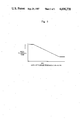
- FIG. 3 is a graph, in which intake air temperature is shown along the horizontal axis and fuel injection time is shown along the vertical axis, for explaining the principle of the present invention.
- the reference numeral 1 generally designates an intake system of an internal combustion engine, not shown in the figure, which in this preferred embodiment is an engine of a type fueled by liquid petroleum gas (LPG), although this is not intended to be limitative of the present invention.
- This intake system 1 has a venturi portion 2, and a main fuel port 3 opens into said venturi portion 2 approximately at the narrowest portion thereof.
- the engine (not shown) is connected to an intake passage 4 of the intake system 1 at its lower and leftmost portion as viewed in FIG. 1, and downstream of the venturi portion 2, between it and said engine, there is provided in said intake passage 4 a throttle valve 6 of the butterfly type, as rotatably mounted supported by a throttle valve shaft 5.
- the throttle valve 6 does not completely close the intake passage 4 even when it is in the idling position as shown in FIG. 1, so as to allow a small amount of LPG supplied to the main fuel port 3 in idling operation of the engine to flow toward the engine cylinders.
- An LPG regulator valve 20 is of a per se known type, and has a primary pressure reduction chamber 23 and a secondary pressure reduction chamber 24.
- Liquid petroleum gas (LPG) is supplied from a tank (not shown) through a fuel inlet port 25 into the primary pressure reduction chamber 23, and undergoes a primary pressure reduction therein to a pressure somewhat over atmospheric pressure. Then further some of this LPG is supplied from said primary pressure reduction chamber 23 to a secondary pressure reduction chamber 24, with its pressure being further reduced to become substantially equal to atmospheric pressure.
- the primary pressure reduction chambr 23 is open to a slow fuel take out port 22, and the secondary pressure reduction chamber 24 is open to a main fuel take out port 21.
- the main fuel take out port 21 is connected via a main fuel line 7 to the main fuel port 3 opening in the venturi portion 2, and the slow fuel take out port 22 is also connected via a slow fuel line 8 to said main fuel port 3.
- the opening and closing of the slow fuel take out port 22 is controlled by a slow lock valve 26 which incorporates a slow lock diaphragm device 27 which incorporates a diaphragm chamber 28.
- This diaphragm chamber 28 is connected via a vacuum conduit 29 with a port designated as "a" of an electromagnetic vacuum switching valve 30.
- a second port designated as “b” of said valve 30 is connected via another vacuum conduit 31 with a first vacuum take out port 11 which opens to the intake passage 4 to be always upstream of the throttle valve 6.
- a third port designated as "c” of said electromagnetic vacuum switching valve 30 is connected via another vacuum conduit 32 with a second vacuum take out port 12 which opens to said intake passage 4 to be always downstream of said throttle valve 6.
- an electrical control device 40 which further selectively supplies actuating electrical energy to a fuel injector valve 10 provided in the intake passage 4 of the engine just downstream of the throttle valve 6; this fuel injector valve 10 is supplied with LPG at its inlet via a fuel line 9 which branches off from the fuel line 8.
- This electrical control device 40 includes a microcomputer which operates according to a control program implanted therein. And this microcomputer receives as inputs: information relating to the revolution speed of the engine from an engine revolution speed sensor 41, information relating to the amount of opening of the throttle valve 6 from a throttle valve opening amount sensor 42 mounted to the throttle shaft 5, and information relating to the temperature of the air which is being sucked into the intake system 1 of the engine from an intake air temperature sensor 43 mounted in said intake system 1 upstream of the venturi portion 2.
- the electromagnetic vacuum switching valve 30 When the engine revolution speed, as indicated by the engine revolution speed sensor 41, is greater than a determinate value, and further the throttle valve 6, as indicated by the throttle valve opening amount sensor 42, is in the idling closed position, the electromagnetic vacuum switching valve 30 is energized by the electrical control device 40, so as to perform deceleration fuel cut off; and, when said electromagnetic vacuum switching valve 30 is deenergized for the end of fuel cut off, at substantially the same time an injection signal is dispatched by the electrical control device 40 to turn the fuel injector 10 on for a period determined by the temperature of the air which is being sucked into the intake system 1 of the engine, as determined by the intake air temperature sensor 43.
- FIG. 2 there is shown a flow chart for aiding in the explanation of the action of the part of the control program for this microcomputer incorporated in the electrical control device 40 which deals with the ending of fuel cut off. This portion of said control program is incorporated in a main routine for said microcomputer.
- step 102 the value of a flag F is set to zero, and then the flow of control passes to exit this program portion, without doing anything further.
- step 103 a judgement is made as to whether or not the throttle valve 6 is currently in idling position, or not; this judgement is made based upon the current value of the output from the throttle valve opening amount sensor 42. If the answer is YES, i.e. currently the throttle valve 6 of the engine is in the idling position, then the flow of control passes to the step 104; but if the answer is NO, then the flow of control passes to exit this program portion, without doing anything further.
- step 104 a judgement is made as to whether or not the value of the flag F is currently unity, or not. If the answer is YES, then the flow of control passes to exit this program portion, without doing anything further. On the other hand, if the answer is NO, then the flow of control passes to the step 105.
- step 105 a judgement is made as to whether or not a value DNe representative of the rate of reduction of the revolution speed of the engine, as determined from the output of the engine revolution speed sensor 41, is greater than a determinate value A, or not. If the answer is NO, then the flow of control passes to exit this program portion, without doing anything further; while, if the answer is YES, then the flow of control passes to the step 106.
- the length of the time for fuel injection through the fuel injection valve 10 is determined according to the current value of the temperature of the air which is being sucked into the intake system 1 of the engine, as determined by the intake air temperature sensor 43, as per the characteristics shown in FIG. 3: in other words, the higher is the intake air temperature within a certain range, the lower is the fuel injection time, and outside this range on either side thereof the fuel injection time is substantially constant. Then the flow of control passes to the step 107.
- a signal is outputted to the fuel injector 10 to open it for the length of time decided in the step 106.
- LPG flows through the fuel line 9 to the fuel injector 10 and therethrough into the intake system 1 and to the engine at a substantially constant rate.
- the value of the flag F is set to 1, so as to avoid performing this fuel injection procedure more than once; and then the flow of control passes to exit this program portion.
Landscapes
- Engineering & Computer Science (AREA)
- Chemical & Material Sciences (AREA)
- Combustion & Propulsion (AREA)
- Mechanical Engineering (AREA)
- General Engineering & Computer Science (AREA)
- Electrical Control Of Air Or Fuel Supplied To Internal-Combustion Engine (AREA)
Abstract
Description
Claims (8)
Applications Claiming Priority (2)
| Application Number | Priority Date | Filing Date | Title |
|---|---|---|---|
| JP60-31934 | 1985-02-20 | ||
| JP60031934A JPS61192826A (en) | 1985-02-20 | 1985-02-20 | Fuel feed control method on fuel cut restoration in internal-combustion engine |
Publications (1)
| Publication Number | Publication Date |
|---|---|
| US4696278A true US4696278A (en) | 1987-09-29 |
Family
ID=12344795
Family Applications (1)
| Application Number | Title | Priority Date | Filing Date |
|---|---|---|---|
| US06/830,879 Expired - Fee Related US4696278A (en) | 1985-02-20 | 1986-02-19 | Method and device for control of internal combustion engine at end of fuel cut off |
Country Status (2)
| Country | Link |
|---|---|
| US (1) | US4696278A (en) |
| JP (1) | JPS61192826A (en) |
Cited By (18)
| Publication number | Priority date | Publication date | Assignee | Title |
|---|---|---|---|---|
| US4790275A (en) * | 1987-01-27 | 1988-12-13 | Mazda Motor Corporation | Fuel supply cut-off control system for engine of an automotive vehicle |
| US4919094A (en) * | 1987-06-17 | 1990-04-24 | Hitachi, Ltd. | Engine control apparatus |
| US4989573A (en) * | 1988-07-11 | 1991-02-05 | Yamaha Hatsudoki Kabushiki Kaisha | Gas powered engine with glow plug ignition |
| US5136986A (en) * | 1991-04-26 | 1992-08-11 | Energy Conversions, Inc. | Dual fuel injection structure |
| US5255657A (en) * | 1990-06-27 | 1993-10-26 | Motoren-Werke Mannheim Ag | Gas engine |
| US5337722A (en) * | 1992-04-16 | 1994-08-16 | Yamaha Hatsudoki Kabushiki Kaisha | Fuel control and feed system for gas fueled engine |
| US5445131A (en) * | 1993-03-12 | 1995-08-29 | Mazda Motor Corporation | Fuel control system for engine |
| US5474053A (en) * | 1993-08-31 | 1995-12-12 | Yamaha Hatsudoki Kabushiki Kaisha | Control for gaseous fueled engine |
| US5546919A (en) * | 1993-08-31 | 1996-08-20 | Yamaha Hatsudoki Kabushiki Kaisha | Operating arrangement for gaseous fueled engine |
| US5575266A (en) * | 1993-08-31 | 1996-11-19 | Yamaha Hatsudoki Kabushiki Kaisha | Method of operating gaseous fueled engine |
| US5588416A (en) * | 1994-03-15 | 1996-12-31 | Yamaha Hatsudoki Kabushiki Kaisha | Fuel control system for gaseous fueled engine |
| US5755203A (en) * | 1994-03-14 | 1998-05-26 | Yamaha Hatsudoki Kabushiki Kaisha | Charge-forming system for gaseous fueled engine |
| US6250261B1 (en) * | 1999-07-13 | 2001-06-26 | Hector Francisco Santarossa | Device for feeding natural compressed gas to a diesel engine |
| US20040187843A1 (en) * | 2001-10-19 | 2004-09-30 | Toshihiko Yamashita | Fuel cut control method |
| US6868830B1 (en) * | 2004-05-14 | 2005-03-22 | James Meyer Aspen Engineering Services, Llc | Venturi induction for internal combustion engines |
| US7019626B1 (en) | 2005-03-03 | 2006-03-28 | Omnitek Engineering, Inc. | Multi-fuel engine conversion system and method |
| US20110067671A1 (en) * | 2009-09-01 | 2011-03-24 | Laimboeck Franz J | Non-soot emitting fuel combustion chamber |
| US20110068188A1 (en) * | 2009-09-01 | 2011-03-24 | Laimboeck Franz J | Fuel injector for permitting efficient combustion |
Families Citing this family (1)
| Publication number | Priority date | Publication date | Assignee | Title |
|---|---|---|---|---|
| JP2808658B2 (en) * | 1989-04-28 | 1998-10-08 | スズキ株式会社 | Fuel injection control device for internal combustion engine |
Citations (8)
| Publication number | Priority date | Publication date | Assignee | Title |
|---|---|---|---|---|
| US4240390A (en) * | 1978-09-01 | 1980-12-23 | Toyota Jidosha Kogyo Kabushiki Kaisha | Air-fuel ratio control system in internal combustion engine |
| US4430978A (en) * | 1981-09-28 | 1984-02-14 | The Bendix Corporation | Direct liquid injection of liquid petroleum gas |
| US4452212A (en) * | 1981-01-26 | 1984-06-05 | Nissan Motor Co., Ltd. | Fuel supply control system for an internal combustion engine |
| US4462375A (en) * | 1982-03-23 | 1984-07-31 | Toyota Jidosha Kabushiki Kaisha | Method and apparatus for controlling fuel supply of an internal combustion engine |
| US4489696A (en) * | 1981-08-13 | 1984-12-25 | Toyota Jidosha Kabushiki Kaisha | Method and apparatus for controlling the fuel-feeding rate of an internal combustion engine |
| JPS6049A (en) * | 1983-06-14 | 1985-01-05 | Kawaguchiko Seimitsu Kk | Flat type battery |
| US4499879A (en) * | 1983-04-28 | 1985-02-19 | General Motors Corporation | Fuel supply system for an internal combustion engine |
| US4527521A (en) * | 1982-06-09 | 1985-07-09 | Honda Giken Kogyo Kabushiki Kaisha | Method for controlling fuel supply to an internal combustion engine after termination of fuel cut |
-
1985
- 1985-02-20 JP JP60031934A patent/JPS61192826A/en active Pending
-
1986
- 1986-02-19 US US06/830,879 patent/US4696278A/en not_active Expired - Fee Related
Patent Citations (8)
| Publication number | Priority date | Publication date | Assignee | Title |
|---|---|---|---|---|
| US4240390A (en) * | 1978-09-01 | 1980-12-23 | Toyota Jidosha Kogyo Kabushiki Kaisha | Air-fuel ratio control system in internal combustion engine |
| US4452212A (en) * | 1981-01-26 | 1984-06-05 | Nissan Motor Co., Ltd. | Fuel supply control system for an internal combustion engine |
| US4489696A (en) * | 1981-08-13 | 1984-12-25 | Toyota Jidosha Kabushiki Kaisha | Method and apparatus for controlling the fuel-feeding rate of an internal combustion engine |
| US4430978A (en) * | 1981-09-28 | 1984-02-14 | The Bendix Corporation | Direct liquid injection of liquid petroleum gas |
| US4462375A (en) * | 1982-03-23 | 1984-07-31 | Toyota Jidosha Kabushiki Kaisha | Method and apparatus for controlling fuel supply of an internal combustion engine |
| US4527521A (en) * | 1982-06-09 | 1985-07-09 | Honda Giken Kogyo Kabushiki Kaisha | Method for controlling fuel supply to an internal combustion engine after termination of fuel cut |
| US4499879A (en) * | 1983-04-28 | 1985-02-19 | General Motors Corporation | Fuel supply system for an internal combustion engine |
| JPS6049A (en) * | 1983-06-14 | 1985-01-05 | Kawaguchiko Seimitsu Kk | Flat type battery |
Cited By (21)
| Publication number | Priority date | Publication date | Assignee | Title |
|---|---|---|---|---|
| US4790275A (en) * | 1987-01-27 | 1988-12-13 | Mazda Motor Corporation | Fuel supply cut-off control system for engine of an automotive vehicle |
| US4919094A (en) * | 1987-06-17 | 1990-04-24 | Hitachi, Ltd. | Engine control apparatus |
| US4989573A (en) * | 1988-07-11 | 1991-02-05 | Yamaha Hatsudoki Kabushiki Kaisha | Gas powered engine with glow plug ignition |
| US5255657A (en) * | 1990-06-27 | 1993-10-26 | Motoren-Werke Mannheim Ag | Gas engine |
| US5529048A (en) * | 1991-04-20 | 1996-06-25 | Yamaha Hatsudoki Kabushiki Kaisha | Fuel control and feed system for gas fueled engine |
| US5136986A (en) * | 1991-04-26 | 1992-08-11 | Energy Conversions, Inc. | Dual fuel injection structure |
| US5337722A (en) * | 1992-04-16 | 1994-08-16 | Yamaha Hatsudoki Kabushiki Kaisha | Fuel control and feed system for gas fueled engine |
| US5445131A (en) * | 1993-03-12 | 1995-08-29 | Mazda Motor Corporation | Fuel control system for engine |
| US5575266A (en) * | 1993-08-31 | 1996-11-19 | Yamaha Hatsudoki Kabushiki Kaisha | Method of operating gaseous fueled engine |
| US5546919A (en) * | 1993-08-31 | 1996-08-20 | Yamaha Hatsudoki Kabushiki Kaisha | Operating arrangement for gaseous fueled engine |
| US5474053A (en) * | 1993-08-31 | 1995-12-12 | Yamaha Hatsudoki Kabushiki Kaisha | Control for gaseous fueled engine |
| US5615661A (en) * | 1993-08-31 | 1997-04-01 | Yamaha Hatsudoki Kabushiki Kaisha | Control for engine |
| US5755203A (en) * | 1994-03-14 | 1998-05-26 | Yamaha Hatsudoki Kabushiki Kaisha | Charge-forming system for gaseous fueled engine |
| US5588416A (en) * | 1994-03-15 | 1996-12-31 | Yamaha Hatsudoki Kabushiki Kaisha | Fuel control system for gaseous fueled engine |
| US6250261B1 (en) * | 1999-07-13 | 2001-06-26 | Hector Francisco Santarossa | Device for feeding natural compressed gas to a diesel engine |
| US20040187843A1 (en) * | 2001-10-19 | 2004-09-30 | Toshihiko Yamashita | Fuel cut control method |
| US6830038B2 (en) * | 2001-10-19 | 2004-12-14 | Yamaha Hatsudoki Kabushiki Kaisha | Fuel cut control method |
| US6868830B1 (en) * | 2004-05-14 | 2005-03-22 | James Meyer Aspen Engineering Services, Llc | Venturi induction for internal combustion engines |
| US7019626B1 (en) | 2005-03-03 | 2006-03-28 | Omnitek Engineering, Inc. | Multi-fuel engine conversion system and method |
| US20110067671A1 (en) * | 2009-09-01 | 2011-03-24 | Laimboeck Franz J | Non-soot emitting fuel combustion chamber |
| US20110068188A1 (en) * | 2009-09-01 | 2011-03-24 | Laimboeck Franz J | Fuel injector for permitting efficient combustion |
Also Published As
| Publication number | Publication date |
|---|---|
| JPS61192826A (en) | 1986-08-27 |
Similar Documents
| Publication | Publication Date | Title |
|---|---|---|
| US4696278A (en) | Method and device for control of internal combustion engine at end of fuel cut off | |
| US4304210A (en) | System and method for controlling EGR in internal combustion engine | |
| US4047509A (en) | Method and device for recirculating exhaust gases of internal combustion engines | |
| KR910003245A (en) | Control device of internal combustion engine | |
| US4452217A (en) | Exhaust gas recirculation control system for a diesel engine and control method therefor | |
| US4300516A (en) | System and method for controlling exhaust gas recirculation | |
| JPH02277919A (en) | Suction device of multi-cylinder engine | |
| KR20030031840A (en) | Method of switching fuel in engine and apparatus thereof | |
| US4376369A (en) | Device for controlling primary and secondary air/fuel ratios for internal combustion engine | |
| US4450806A (en) | Intake air throttle device of a diesel engine | |
| US2700967A (en) | Fuel system of internal-combustion engines | |
| US5337715A (en) | Engine deceleration intake air flow reduction and fuel shut-off control | |
| US4955342A (en) | Idle revolution number control apparatus for carbureter | |
| JPS58131339A (en) | Method for stopping operation of diesel engine | |
| US4354472A (en) | Fuel injection system | |
| US20020134339A1 (en) | Manually guided implement | |
| JPS61229943A (en) | Method of controlling fuel supply in fuel cut return in internal-combustion engine | |
| JPH04259653A (en) | Rust preventive device for egr valve | |
| JPS621405Y2 (en) | ||
| JPS6157933B2 (en) | ||
| JPS61261633A (en) | Fuel cut controller | |
| JPS61152962A (en) | Fuel injection device for internal-combustion engine with supercharger | |
| JPS5918120Y2 (en) | engine carburetor | |
| JPH0236929Y2 (en) | ||
| JPS6126607Y2 (en) |
Legal Events
| Date | Code | Title | Description |
|---|---|---|---|
| AS | Assignment |
Owner name: TOYOTA JIDOSHA KABUSHIKI KAISHA, 1 TOYOTACHO, TOYO Free format text: ASSIGNMENT OF ASSIGNORS INTEREST.;ASSIGNORS:ITO, TOSHIMITSU;MURATA, CHIGAKU;REEL/FRAME:004519/0258 Effective date: 19860108 Owner name: TOYOTA JIDOSHA KABUSHIKI KAISHA,JAPAN Free format text: ASSIGNMENT OF ASSIGNORS INTEREST;ASSIGNORS:ITO, TOSHIMITSU;MURATA, CHIGAKU;REEL/FRAME:004519/0258 Effective date: 19860108 |
|
| AS | Assignment |
Owner name: TDW DELAWARE, INC., A CORP. OF DE. Free format text: ASSIGNMENT OF ASSIGNORS INTEREST.;ASSIGNOR:T. D. WILLIAMSON, INC.,;REEL/FRAME:004915/0907 Effective date: 19880805 |
|
| FPAY | Fee payment |
Year of fee payment: 4 |
|
| REMI | Maintenance fee reminder mailed | ||
| LAPS | Lapse for failure to pay maintenance fees | ||
| FP | Lapsed due to failure to pay maintenance fee |
Effective date: 19951004 |
|
| STCH | Information on status: patent discontinuation |
Free format text: PATENT EXPIRED DUE TO NONPAYMENT OF MAINTENANCE FEES UNDER 37 CFR 1.362 |