US4690206A - Nuclear steam generator wrapper barrel/tube support plate connection assembly and radial tuning method for assembling same - Google Patents
Nuclear steam generator wrapper barrel/tube support plate connection assembly and radial tuning method for assembling same Download PDFInfo
- Publication number
- US4690206A US4690206A US06/757,719 US75771985A US4690206A US 4690206 A US4690206 A US 4690206A US 75771985 A US75771985 A US 75771985A US 4690206 A US4690206 A US 4690206A
- Authority
- US
- United States
- Prior art keywords
- tube support
- support plate
- recited
- assembly
- spacer means
- Prior art date
- Legal status (The legal status is an assumption and is not a legal conclusion. Google has not performed a legal analysis and makes no representation as to the accuracy of the status listed.)
- Expired - Lifetime
Links
- 238000000034 method Methods 0.000 title claims abstract description 21
- 230000036316 preload Effects 0.000 claims abstract description 47
- 125000006850 spacer group Chemical group 0.000 claims description 52
- 239000000463 material Substances 0.000 claims description 19
- 229910052751 metal Inorganic materials 0.000 claims description 14
- 239000002184 metal Substances 0.000 claims description 14
- 230000003993 interaction Effects 0.000 abstract description 3
- 239000012530 fluid Substances 0.000 description 17
- 238000011068 loading method Methods 0.000 description 13
- 238000005260 corrosion Methods 0.000 description 8
- 239000011368 organic material Substances 0.000 description 8
- 230000007797 corrosion Effects 0.000 description 7
- 238000013461 design Methods 0.000 description 6
- 230000000694 effects Effects 0.000 description 6
- 229910001220 stainless steel Inorganic materials 0.000 description 6
- 229910000975 Carbon steel Inorganic materials 0.000 description 5
- 239000010962 carbon steel Substances 0.000 description 5
- 229910001293 incoloy Inorganic materials 0.000 description 4
- 239000000356 contaminant Substances 0.000 description 3
- 230000007613 environmental effect Effects 0.000 description 3
- 238000004519 manufacturing process Methods 0.000 description 3
- 239000002861 polymer material Substances 0.000 description 3
- 230000001052 transient effect Effects 0.000 description 3
- PXHVJJICTQNCMI-UHFFFAOYSA-N Nickel Chemical compound [Ni] PXHVJJICTQNCMI-UHFFFAOYSA-N 0.000 description 2
- 230000003466 anti-cipated effect Effects 0.000 description 2
- 230000000712 assembly Effects 0.000 description 2
- 238000000429 assembly Methods 0.000 description 2
- 239000000470 constituent Substances 0.000 description 2
- 230000001419 dependent effect Effects 0.000 description 2
- 230000010339 dilation Effects 0.000 description 2
- 238000004090 dissolution Methods 0.000 description 2
- 229930195733 hydrocarbon Natural products 0.000 description 2
- 150000002430 hydrocarbons Chemical class 0.000 description 2
- 238000012986 modification Methods 0.000 description 2
- 230000004048 modification Effects 0.000 description 2
- 229920000642 polymer Polymers 0.000 description 2
- 238000001228 spectrum Methods 0.000 description 2
- 230000003068 static effect Effects 0.000 description 2
- 238000012360 testing method Methods 0.000 description 2
- 239000011573 trace mineral Substances 0.000 description 2
- 235000013619 trace mineral Nutrition 0.000 description 2
- 238000012546 transfer Methods 0.000 description 2
- XLYOFNOQVPJJNP-UHFFFAOYSA-N water Substances O XLYOFNOQVPJJNP-UHFFFAOYSA-N 0.000 description 2
- VYZAMTAEIAYCRO-UHFFFAOYSA-N Chromium Chemical compound [Cr] VYZAMTAEIAYCRO-UHFFFAOYSA-N 0.000 description 1
- NINIDFKCEFEMDL-UHFFFAOYSA-N Sulfur Chemical compound [S] NINIDFKCEFEMDL-UHFFFAOYSA-N 0.000 description 1
- 239000005864 Sulphur Substances 0.000 description 1
- 230000003044 adaptive effect Effects 0.000 description 1
- 230000002411 adverse Effects 0.000 description 1
- 230000008901 benefit Effects 0.000 description 1
- 239000006227 byproduct Substances 0.000 description 1
- 230000008859 change Effects 0.000 description 1
- 238000006243 chemical reaction Methods 0.000 description 1
- 229910052804 chromium Inorganic materials 0.000 description 1
- 239000011651 chromium Substances 0.000 description 1
- 230000006835 compression Effects 0.000 description 1
- 238000007906 compression Methods 0.000 description 1
- 230000001010 compromised effect Effects 0.000 description 1
- 239000012141 concentrate Substances 0.000 description 1
- 238000010276 construction Methods 0.000 description 1
- 230000001351 cycling effect Effects 0.000 description 1
- 238000011161 development Methods 0.000 description 1
- 230000005489 elastic deformation Effects 0.000 description 1
- 230000008030 elimination Effects 0.000 description 1
- 238000003379 elimination reaction Methods 0.000 description 1
- 239000000945 filler Substances 0.000 description 1
- 238000005259 measurement Methods 0.000 description 1
- 230000007246 mechanism Effects 0.000 description 1
- 150000002739 metals Chemical class 0.000 description 1
- 230000000116 mitigating effect Effects 0.000 description 1
- 229910052759 nickel Inorganic materials 0.000 description 1
- 230000002093 peripheral effect Effects 0.000 description 1
- 239000007787 solid Substances 0.000 description 1
- 239000010935 stainless steel Substances 0.000 description 1
- 239000000126 substance Substances 0.000 description 1
- 230000007704 transition Effects 0.000 description 1
- 238000003466 welding Methods 0.000 description 1
Images


Classifications
-
- F—MECHANICAL ENGINEERING; LIGHTING; HEATING; WEAPONS; BLASTING
- F22—STEAM GENERATION
- F22B—METHODS OF STEAM GENERATION; STEAM BOILERS
- F22B37/00—Component parts or details of steam boilers
- F22B37/02—Component parts or details of steam boilers applicable to more than one kind or type of steam boiler
- F22B37/10—Water tubes; Accessories therefor
- F22B37/20—Supporting arrangements, e.g. for securing water-tube sets
- F22B37/205—Supporting and spacing arrangements for tubes of a tube bundle
-
- F—MECHANICAL ENGINEERING; LIGHTING; HEATING; WEAPONS; BLASTING
- F28—HEAT EXCHANGE IN GENERAL
- F28D—HEAT-EXCHANGE APPARATUS, NOT PROVIDED FOR IN ANOTHER SUBCLASS, IN WHICH THE HEAT-EXCHANGE MEDIA DO NOT COME INTO DIRECT CONTACT
- F28D7/00—Heat-exchange apparatus having stationary tubular conduit assemblies for both heat-exchange media, the media being in contact with different sides of a conduit wall
- F28D7/06—Heat-exchange apparatus having stationary tubular conduit assemblies for both heat-exchange media, the media being in contact with different sides of a conduit wall the conduits having a single U-bend
-
- F—MECHANICAL ENGINEERING; LIGHTING; HEATING; WEAPONS; BLASTING
- F28—HEAT EXCHANGE IN GENERAL
- F28F—DETAILS OF HEAT-EXCHANGE AND HEAT-TRANSFER APPARATUS, OF GENERAL APPLICATION
- F28F9/00—Casings; Header boxes; Auxiliary supports for elements; Auxiliary members within casings
- F28F9/001—Casings in the form of plate-like arrangements; Frames enclosing a heat exchange core
-
- F—MECHANICAL ENGINEERING; LIGHTING; HEATING; WEAPONS; BLASTING
- F28—HEAT EXCHANGE IN GENERAL
- F28F—DETAILS OF HEAT-EXCHANGE AND HEAT-TRANSFER APPARATUS, OF GENERAL APPLICATION
- F28F2265/00—Safety or protection arrangements; Arrangements for preventing malfunction
- F28F2265/26—Safety or protection arrangements; Arrangements for preventing malfunction for allowing differential expansion between elements
-
- Y—GENERAL TAGGING OF NEW TECHNOLOGICAL DEVELOPMENTS; GENERAL TAGGING OF CROSS-SECTIONAL TECHNOLOGIES SPANNING OVER SEVERAL SECTIONS OF THE IPC; TECHNICAL SUBJECTS COVERED BY FORMER USPC CROSS-REFERENCE ART COLLECTIONS [XRACs] AND DIGESTS
- Y10—TECHNICAL SUBJECTS COVERED BY FORMER USPC
- Y10S—TECHNICAL SUBJECTS COVERED BY FORMER USPC CROSS-REFERENCE ART COLLECTIONS [XRACs] AND DIGESTS
- Y10S165/00—Heat exchange
- Y10S165/051—Heat exchange having expansion and contraction relieving or absorbing means
- Y10S165/052—Heat exchange having expansion and contraction relieving or absorbing means for cylindrical heat exchanger
- Y10S165/06—Expandable casing for cylindrical heat exchanger
- Y10S165/061—Expandable casing for cylindrical heat exchanger for plural cylindrical heat exchangers
-
- Y—GENERAL TAGGING OF NEW TECHNOLOGICAL DEVELOPMENTS; GENERAL TAGGING OF CROSS-SECTIONAL TECHNOLOGIES SPANNING OVER SEVERAL SECTIONS OF THE IPC; TECHNICAL SUBJECTS COVERED BY FORMER USPC CROSS-REFERENCE ART COLLECTIONS [XRACs] AND DIGESTS
- Y10—TECHNICAL SUBJECTS COVERED BY FORMER USPC
- Y10T—TECHNICAL SUBJECTS COVERED BY FORMER US CLASSIFICATION
- Y10T29/00—Metal working
- Y10T29/49—Method of mechanical manufacture
- Y10T29/4935—Heat exchanger or boiler making
Definitions
- This invention relates to nuclear steam generators and, more particularly, to a connection assembly and a method related thereto for eliminating or selectively minimizing the structural interference caused by thermal expansion during operation of a nuclear steam generator between a wrapper barrel made of a material having a particular coefficient of thermal expansion and a tube support plate system whose constituent plates have a relatively higher coefficient of thermal expansion.
- FIG. 1 A typical nuclear steam generator of the type generally referred to herein is described in commonly owned U.S. Pat. No. 4,303,043, issued to MALICK, and is shown in FIG. 1 herein.
- a nuclear steam generator which is referred to generally by reference numeral 20, comprises a vertical, outer shell 22 with a primary fluid inlet nozzle 24 and a primary fluid outlet nozzle 26, which are attached near the lower end.
- a vertical, inner shell or wrapper barrel 23 has at its lower end a tubesheet 28, having tube holes 30 formed therein.
- Tubes 38 which are heat transfer tubes shaped with a U-like curvature, are disposed within the wrapper barrel 23 and are attached to the tubesheet 28 by the tube holes 30.
- the tubes 38 which may number about 7,000, form collectively what is known as a tube bundle 40.
- a plurality of tube support plates 33 are horizontally located in and connected to the wrapper barrel 23 for receiving, aligning and providing support to the tubes 38.
- a dividing plate 32 which is attached to both the tubesheet 28 and the outer shell 22, defines a primary fluid inlet plenum 34 and a primary fluid outlet plenum 36.
- a secondary fluid inlet nozzle 42 is disposed on the outer shell 22, while a steam outlet nozzle 44 is attached to the top of the outer shell 22.
- manways 46 are provided through the outer shell 22 to provide access to both the primary fluid inlet plenum 34 and the primary fluid outlet plenum 36, so that access may be had to the entire tubesheet 28.
- primary fluid enters the primary fluid inlet nozzle 24, flows into the primary fluid inlet plenum 34, through the tubes 38, into the primary fluid outlet plenum 36 and exits through the primary fluid outlet nozzle 26. While flowing through the tubes 38, heat is transferred from the primary fluid to a secondary fluid circulating through the tube support plates 33 and around tubes 38, causing the secondary fluid to vaporize and exit through the steam outlet nozzle 44.
- nuclear steam generators such as the one described above, environmental and load conditions must be carefully accommodated.
- environmental conditions conventional nuclear steam generator materials are subject to varying amounts of corrosion, depending upon the type of metals used therein.
- load conditions nuclear steam generators must be designed to sustain conservative estimates of static and dynamic loadings, such as earthquakes or hydraulic accident events, and to maintain the integrity of the primary pressure boundary or tube bundle.
- tube support plates 33 are responsible for aligning the tube bundle 40, maintaining the span lengths or spacings between adjacent tube support plates, providing each tube 38 with adequate restraint at each tube 38/tube support plate 33 intersection, minimizing tube 38 vibration, sustaining static and dynamic loadings, and maintaining the overall integrity of the tube bundle 40 for the useful life of the steam generator.
- each tube 38 is inserted into each tube support plate 33, there is a large number of tube 38/tube support plate 33 intersections.
- a tube support plate 33 made of a metal with improved corrosion resistance and having the required mechanical/structural properties is desired if the probability of damage to the tube support plate 33 is to be reduced.
- the ratios of the mean coefficients of thermal expansion of a tube support plate made of Incoloy 800 Class or Class 347 relative to the wrapper barrel 23 at service conditions are 1.2 and 1.3, respectively.
- the ratios of the mean coefficients of thermal expansion of the conventional tube support plate 33 materials suggested above, e.g., carbon steel and Class 405 stainless steel, to the wrapper barrel 23 are 1.0 and 6.88, respectively.
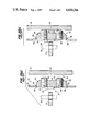
- FIG. 2 illustrates a conventional "locked" wrapper barrel/tube support plate connection assembly, referred to by reference numeral 50, as it appears once assembled, but before operation of the steam generator.
- This assembly 50 is designed without regard for the coefficient of thermal expansion of the material making up the tube support plate 33 or without regard for the coefficient of thermal expansion of the material making up the wrapper barrel 23.
- the wrapper barrel 23 is positioned between the outer shell 22 and each tube support plate 33 holding the tubes 38.
- a jacking assembly 52 usually made of carbon steel and welded to the wrapper barrel 23, projects through a cut-out in the wrapper barrel 23 and fits into an annular space 66 between the wrapper barrel 23 and the outer shell 22.
- the jacking assembly 52 includes: a jacking block 54 attached to the wrapper barrel 23 by seal welds 56 and fillets 58; and one or two threaded jacking studs 60 and 62 which extend a predetermined distance from the jacking block 54 to the outer shell. 22.
- a plurality of these jacking assemblies 52 are circumferentially located at each tube support plate 33 elevation.
- a plurality of solid carbon steel wedges 64 is located in an annular space 67 formed between the wrapper barrel 23 and the tube support plate 33 and fixed during assembly via fillet welds 65 (FIGS. 2(a) and 2(b)).
- the wedges 64 are adjusted to "lock" the tube support plates 33 in place during assembly at each corresponding elevation of each tube support plate 33 and before operation of the steam generator.
- An example of the use of these wedges 64 is described in commonly owned U.S. Pat. No. 4,267,020, issued to BURACK.
- the round periphery of the perforated, expanding tube support plate 33 has the potential of crashing or knocking into the wrapper barrel 23, as shown in FIG. 2(b).
- the jacking studs 60, 62 may be forced against the outer shell 22, and the wrapper barrel 23 may severly deflect locally, ultimately fatigue or even break at the jacking assembly 52 connections thereto, obviously causing a dangerous operating condition.
- this locked assembly 50 is simply not adaptive enough to compensate satisfactorily for combined unexpected stresses upon the steam generator, e.g., thermal transient excursions plus earthquakes or hydraulic accident events.
- a wrapper barrel/tube support plate connection assembly including a wrapper barrel with a first coefficient of thermal expansion, a plurality of tube support plates with a second, relatively higher coefficient of thermal expansion, and means located between the wrapper barrel and the plurality of tube support plates to compensate for thermal expansion of the plurality of tube support plates during heat-up, seismic and thermal transients and normal operation of the steam generator.
- a wrapper barrel/tube support plate connection assembly and a method for assembling same, wherein a locally controlled preload is introduced into the wrapper barrel during assembly thereof.
- the preload is introduced via increased stud thread engagement in the jacking assembly located between the wrapper barrel and the outer shell, thus causing a local deformation in the wrapper barrel at each jacking assembly location.
- This preload is ensured at the point of assembly by controlling stud torque and by discrete radial measurements at every opposing (180° circumferential orientation) jacking assembly location.
- the preload established at cold assembly conditions is based upon full power pressure and temperature operating requirements of a particular steam generator.
- preload can be basically site specific, i.e., tailored or tuned to a particular steam generator design or geometry (i.e., size and thermal or power performance requirements).
- the gap remaining after preload (during manufacture) between each tube support plate and the wrapper barrel is fit with a spacer means including a heat and/or pressure dissolvable, organic, high strength, polymer surface or a belleville spring washer surface.
- This spacer means maintains a tight fit between each tube support plate and the wrapper barrel during assembly and compensates for the lateral loadings incurred during heat-up and operation of the steam generator.
- the dissolving of the spacer is accompanied by the radial growth of the high thermal expansion tube support plate. This growth exceeds that of the wrapper barrel and thus, eliminates the gap originally occupied by the spacer and, furthermore, results in minimal interference or precludes interference entirely.
- the present invention overcomes the disadvantages of the conventional, locked wrapper barrel/tube support plate connection assembly discussed above by eliminating any thermal interference caused by expansion of high coefficient of thermal expansion tube support plates and reduces overall the dynamic loadings of the tube support plates.
- the present invention reduces jacking stud head to outer shell gap, thus further lowering dynamic loading and mitigating increases in required tube support plate thickness which would be required to sustain the higher dynamic loadings.
- the present invention restores the gap between the tube support plate and the wrapper barrel, thus eliminating thermal expansion concerns at this location also.
- FIG. 1 is an elevational, cross-sectional view of a conventional nuclear steam generator
- FIG. 2 is a side, cross-sectional view of a conventional wrapper barrel/tube support plate connection assembly as it appears after assembly, but before operation of the steam generator.
- FIG. 2(a) is a side, cross-sectional view of the conventional wrapper barrel/tube support plate connection assembly shown in FIG. 2 during full power operation of the steam generator.
- FIG. 2(b) is a side, cross-sectional view of the conventional wrapper barrel/tube support plate connection assembly utilizing the conventional and/or advanced tube support plate materials as shown in FIG. 2 at full load temperature and pressure operating conditions.
- FIG. 3 is a top, cross-sectional view of the wrapper barrel/tube support plate connection assembly according to the present invention after assembly, but before operation of the steam generator;
- FIG. 4 is a side, cross-sectional view of the wrapper barrel/tube support plate connection assembly according to the present invention shown in FIG. 3;
- FIG. 5 is a top, cross-sectional view of the wrapper barrel/tube support plate connection assembly according to the present invention during operation;
- FIG. 6 is a side, cross-sectional view of the wrapper barrel/tube support plate connection assembly shown in FIG. 5;
- FIG. 7 is a side, cross-sectional view of one embodiment of a spacer means according to the present invention, illustrating particularly a heat and/or pressure dissolvable, organic, high strength, polymer material applied to a surface of a rectangular shim;
- FIG. 8 is a side, cross-sectional view of another embodiment of the spacer means according to the present invention, illustrating particularly a heat and/or pressure dissolvable, organic, high strength, polymer material applied to a surface of a wedge;
- FIG. 9 is a side, cross-sectional view of another embodiment of the spacer means according to the present invention, illustrating particularly a belleville spring washer attached to a surface of a rectangular shim;
- FIG. 10 is a side, cross-sectional view of another embodiment of the spacer means according to the present invention, illustrating particularly a belleville spring washer attached to a surface of a wedge.
- FIGS. 3-10 illustrate the present invention's wrapper barrel/tube support connection assembly 70 and method for assembling same which generally introduces a locally controlled preload into a wrapper barrel 72 during assembly of the steam generator.
- Preload is defined as the amount of local load upon the support plate periphery and upon the internal diameter of the wrapper barrel resulting from the torque that must be applied to the jacking studs 80 to deform the wrapper barrel 72 during assembly, as will soon be described more fully.
- Determination of preload can be based upon the full power pressure and temperature operating requirements (magnitude and rate by which they are achieved or "ramped") of any steam generator. Therefore, the amount of preload is generally unit or site specific, being dependent upon actual full power operating conditions of a particular steam generator. That is, when fine tuning is performed, there are certain site dependent details that cannot be discarded, for example, specific thermal-hydraulic performance and operating requirements of a particular steam generator model or site and/or specific earthquake spectra of the intended geographic area.
- Factors included in the determination of preload include: the mechanical properties of the wrapper barrel material; the amount of stud 80 torque generally required to deform the wrapper barrel 72 a desired distance; the design and geometry of the connection assembly; the coefficients of thermal expansion of the tube support plates 74 and the wrapper barrel 72; full operating temperature and pressure of the steam generator internals; transient operation, including temperature and pressure of the steam generator internals; and the particular earthquake spectra of the site upon which the steam generator will be installed.
- the resulting preload value represents the amount of deformation which will be effected in the wrapper barrel 72 during unit structuring through increased torque on the studs 80.
- the amount of preload required for an Incoloy 800 Class tube support plate 74 in assignee's pressurized water reactor steam generator design is on the order of 100 mill (0.100 inch).
- This preload is ensured during assembly by controlling stud 80 torque and by radially measuring (at circumferential opposing locations) at each tube support plate 74 elevation the distance between the tube support plate 74 and the wrapper barrel 72 where a jacking assembly 76 is located, as will be described more fully hereafter.
- FIGS. 3-6 represent: (I) how to effect preload during assembly of a nuclear steam generator according to the present invention; and (II) the four phenomena occurring simultaneously during heat-up and operation of the steam generator and the unique configuration thus resulting from the preload.
- Those four phenomena are: (A) expansion of the outer shell 78 due to thermal difference and pressure dilation; (B) relief of the preload when the outer shell 78 expands; (C) expansion of the wrapper barrel 72 due to its normal thermal growth; and (D) expansion of the tube support plates 74 because of their normal thermal growth.
- the present invention is intended to create a preload in a wrapper barrel 72 having a first coefficient of thermal expansion used in combination with a tube support plate 74 having a second, relatively higher coefficient of thermal expansion.
- Tube support plates are usually alphabetically ordered from the bottom to the top of the steam generator.
- Some steam generators differ in that they do not use a plate in the cone region or they include more than six plates in the straight cylindrical region, due to the overall design of the steam generator and the height of the tube bundle 40.
- the geometry of the corresponding jacking blocks or other suitable connection assembly means for the cone region has to correspond to the contour of the cone region, which is in contrast to a straight section of the wrapper barrel where straight jacking blocks are used. Accordingly, effecting preload at the "G"-plate in the transition cone may require particular deflection measuring to effect preload thereat.
- the steam generator outer shell 78 is made stronger, stiffer and thicker (e.g., three inches) than the wrapper barrel 72, (e.g., 3/8 of an inch), as the head 82 of each stud 80 in the jacking assembly 76 is caused to bear against the outer shell 78, a local deformation 86 is introduced into the wrapper barrel 72.
- the gap 87 is usually filled with spacer means 90.
- Each spacer means 90 is about 2 inches long and preferably 4 spacer means (adjacent circumferentially) are used between the jacking assembly 76 and the tube support plate 74.
- the particular shape of the spacer means 90 is determined by how tightly one wants to control the fit at assembly and what the thickness and, hence, bearing area of the support plate is.
- a wedge shape is preferred because it provides a margin of error when positioning the tube support plate 74, i.e., it acts as a variable gap filler and is much easier to assemble with the overall space limitations and manufacturing process constraints.
- the steam generator After assembly of the steam generator is completed and preload is effected in the wrapper barrel 72, the steam generator is ready for heat-up and full operation.
- the outer shell 78 moves from location "W", to location "X". More particularly, pressurizing the steam generator causes the outer shell 78 to expand, as would any vessel under pressure. That is, the outer shell 78, being approximately 3 inches thick, is designed to withstand all expected expansion and pressure stresses during operation. In addition, the shell grows radially due to the thermal characteristics of the steam generator. Thus, when there is a pressure and a thermal difference between the outside atmosphere and the inside of the outer shell 78, the outer shell 78 expands to reach equilibrium.
- the tube support plate 74 also expands according to its coefficient of thermal expansion. That is, since the coefficient of thermal expansion of the tube support plate 74 is far greater than any of the other members discussed above, the tube support plate 74 thermally grows and, hence, expands more radially during operation than the other members due to thermal growth and will catch up, i.e., the tube support plate 78 will close the gap 87 between itself and the expanded wrapper barrel 72. This expansion is represented by the change in location of the outer edge of the tube support plate 74 from location "Y" to location "Z" shown in FIG. 5.
- the outer shell 78 expands 310 mill (0.310 inch) due to the pressure differential between the inside and outside of the outer shell 78 and due to heat expansion. That is, 260 mill (0.260 inch) of the expansion is due to thermal effects and 50 mill (0.050 inch) of the expansion is due to pressure effects. The result is that a 310 mill (0.310 inch) gap 89 is formed between the head 82 of the stud 80 and the inner wall of the outer shell 78.
- preload of the wrapper barrel 72 can be relieved via the stud 80. More particularly, as soon as the outer shell 78 expands, the stud 80 which was initially bearing tight against the outer shell 78 now has the opportunity to relieve the preload. Consequently, the jacking block 84 also has an opportunity to relieve the preload and the connected wrapper barrel 72 is caused to elastically reform and expand 80 mill (0.080 inch). The result is that the gap 89 between the head 82 of the stud 80 and the outer shell 78 is reduced to 230 mill (0.230 inch). However, this movement also results in a wrapper barrel 72/tube support plate 74 gap 87 of 80 mill (0.080 inch). This distance corresponds to the preload originally effected in the wrapper barrel 72.
- each jacking assembly 76 is correspondingly radially displaced 230 mill (0.230 inch).
- the total gap 89 between the outer shell 78 and the stud 80 is then reduced to 0 mill, which is desirable for dynamic analysis purposes because this gap is critical for seismic conditions.
- the gap 89 between the outer shell 78 and the head 82 of the stud 80 is 0 mill (0.0 inch) (i.e., 230 mill minus 230 mill); and (b) the gap 87 between the wrapper barrel 72 and the tube support plate 74 is 310 mill (i.e., 80 mill plus 230 mill).
- the resultant total gap 87 between the tube support plate 74 and wrapper barrel 72 can be controlled to be less than that for a conventional steam generator. That is, it is desired that the gap 87 be small enough so that load is not increased on the tube support plates 74 nor on the wrapper barrel, a structurally thin member relative to the shell. If the gap 87 were to be very large, seismic effects could damage the steam generator. If the gap 87 were to be very small, the tube support plates 74 could crash into the wrapper barrel 72. A gap 87 somewhere in the middle is desired. By properly choosing the preload according to the present invention, a proper gap 87 can be achieved.
- the outer shell 78 and the stud 80 have an interference because these studs 80 are very thick bolts and during operation it is desirable that they should not be knocking against the outer shell 78.
- the present invention can minimize or, preferably, eliminate this gap 89.
- the present invention can create either a tight fit or a very small gap 89 between the outer shell 78 and each stud 80, as desired.
- the spacer means 90 of the present invention includes several alternate embodiments.
- the organic material's constituents would also have to be compatible with the chemistry requirements of the inside of the steam generator.
- hydrocarbons are preferred, as long as consideration is given to preventing excessive amounts of undesirable trace elements (such as lead or sulphur) in the hydrocarbons.
- the dissolvable organic material in any case, is of relatively negligible volume as compared to the secondary fluid system volume and, therefore, no chemical interference with the secondary side fluid would be anticipated.
- dissolvable organic members have already been used in steam generators, but only to help insert tubes into the tubesheet. So there is precedence for the organic material and its trace elements being acceptable in a steam generator.
- the dissolvable spacer means 90 is also intended to sustain lateral loadings incurred during heat-up and operation of the steam generator. More particularly, the spacer means 90 having the organic material surface dissolves or deconstitutes itself as the temperature and/or pressure increases to that corresponding to full power. The resultant radial gap 87 between the wrapper barrel 72 and the tube support plate 74 will then be accommodated by the normal expansion of the tube support plate 74.
- the entire spacer means 90 or any part thereof could be made of a dissolvable organic material. Accordingly, if the temperature and/or pressure got to be such that the entire wedge dissolved, optimum tube support plate 74 orientation would be provided. This is so because it is not desired to have the edge of the tube support plate 74 crash into the jacking block 84 of the wrapper barrel 72. An internal gap between the edge of the tube support plate 74 or its periphery and the inside diameter of the wrapper barrel 72 is acceptable during full power operation, since the dead and live loads of the tube support plate 74 itself can easily be supported by selectively distributed vertical supporting and span preserving vibration/structural elements called "stay rods" (not shown). These stay rods are supported by welding and are threaded into the tubesheet, the top tube support plate and full length through all other tube support plates at selected locations.
- FIGS. 9 and 10 illustrate, respectively, a metallic, rectangular shim 100 and a wedge 104 having a deflection-controlled, bellevelle spring 102 and 106, respectively, attached to a surface of each.
- the spring-surfaced spacer means 90 maintains a tight fit between the tube support plate 74 and the wrapper barrel 72 during assembly and before operation, as do the wedges 64 (FIG. 2) of the prior art.
- the spacer means 90 having the spring surface is also intended to sustain lateral loadings incurred during heat-up of the steam generator. This embodiment of the spacer means 90 is biased by the expanding tube support plate 74 as the temperature and/or pressure is increased to full power.
Landscapes
- Engineering & Computer Science (AREA)
- Physics & Mathematics (AREA)
- Thermal Sciences (AREA)
- Mechanical Engineering (AREA)
- General Engineering & Computer Science (AREA)
- Heat-Exchange Devices With Radiators And Conduit Assemblies (AREA)
- Monitoring And Testing Of Nuclear Reactors (AREA)
Priority Applications (5)
| Application Number | Priority Date | Filing Date | Title |
|---|---|---|---|
| US06/757,719 US4690206A (en) | 1985-07-22 | 1985-07-22 | Nuclear steam generator wrapper barrel/tube support plate connection assembly and radial tuning method for assembling same |
| FR8610577A FR2585110A1 (fr) | 1985-07-22 | 1986-07-21 | Ensemble de liaison enveloppe/plaques de support de tubes pour generateur nucleaire de vapeur et procede d'ajustement radial pour assembler l'ensemble |
| IT21198/86A IT1198002B (it) | 1985-07-22 | 1986-07-21 | Complesso di collegamento fra il corpo cilindrico di fasciame e le piastre di supporte dei tubi di un generatore nucleare,e metodo di messa a punto radiale per il suo montaggio |
| GB8617809A GB2178146B (en) | 1985-07-22 | 1986-07-21 | Nuclear steam generator wrapper barrel/tube support plate connection assembly and radial tuning method for assembling same |
| JP61170996A JPH0663605B2 (ja) | 1985-07-22 | 1986-07-22 | ラツパ−・管支持板接続アセンブリ、及びその組立方法 |
Applications Claiming Priority (1)
| Application Number | Priority Date | Filing Date | Title |
|---|---|---|---|
| US06/757,719 US4690206A (en) | 1985-07-22 | 1985-07-22 | Nuclear steam generator wrapper barrel/tube support plate connection assembly and radial tuning method for assembling same |
Publications (1)
| Publication Number | Publication Date |
|---|---|
| US4690206A true US4690206A (en) | 1987-09-01 |
Family
ID=25048939
Family Applications (1)
| Application Number | Title | Priority Date | Filing Date |
|---|---|---|---|
| US06/757,719 Expired - Lifetime US4690206A (en) | 1985-07-22 | 1985-07-22 | Nuclear steam generator wrapper barrel/tube support plate connection assembly and radial tuning method for assembling same |
Country Status (5)
| Country | Link |
|---|---|
| US (1) | US4690206A (ja) |
| JP (1) | JPH0663605B2 (ja) |
| FR (1) | FR2585110A1 (ja) |
| GB (1) | GB2178146B (ja) |
| IT (1) | IT1198002B (ja) |
Cited By (16)
| Publication number | Priority date | Publication date | Assignee | Title |
|---|---|---|---|---|
| US5082050A (en) * | 1990-05-29 | 1992-01-21 | Solar Turbines Incorporated | Thermal restraint system for a circular heat exchanger |
| FR2707372A1 (fr) * | 1993-07-05 | 1995-01-13 | Framatome Sa | Dispositif de maintien radial de l'enveloppe de faisceau et des plaques-entretoises d'un générateur de vapeur par des butées à excentrique. |
| FR2707373A1 (fr) * | 1993-07-05 | 1995-01-13 | Framatome Sa | Dispositif de maintien radial de l'enveloppe de faisceau et des plaques-entretoises d'un générateur de vapeur. |
| EP0648974A1 (fr) * | 1993-10-14 | 1995-04-19 | Framatome | Dispositif de maintien radial de l'enveloppe de faisceau et des plaques-entretoises d'un générateur de vapeur par des butées à positionnement élastique |
| FR2712960A1 (fr) * | 1993-11-26 | 1995-06-02 | Framatome Sa | Dispositif de maintien radial de l'enveloppe de faisceau et des plaques-entretoises d'un générateur de vapeur par des butées à vis prisonnière. |
| US6498827B1 (en) * | 1999-11-01 | 2002-12-24 | Babcock & Wilcox Canada, Ltd. | Heat exchanger tube support structure |
| US20030159815A1 (en) * | 2000-03-31 | 2003-08-28 | Wilson Alexandria Bruce | Heat exchanger |
| US20040146134A1 (en) * | 2002-10-31 | 2004-07-29 | Klarner Richard G. | Heat exchanger tube support structure |
| US20050013400A1 (en) * | 2003-03-26 | 2005-01-20 | Wivagg Adrian P. | Jet pump assembly repair method |
| US20050087330A1 (en) * | 2003-10-28 | 2005-04-28 | Yungmo Kang | Recuperator construction for a gas turbine engine |
| US20050098309A1 (en) * | 2003-10-28 | 2005-05-12 | Yungmo Kang | Recuperator assembly and procedures |
| US7543591B1 (en) | 2006-02-21 | 2009-06-09 | Karen Munsil | Pre-charged folded compacts for coloring hair |
| US20090154631A1 (en) * | 2007-12-14 | 2009-06-18 | Wepfer Robert M | Hatch mechanical locking system |
| US20100018689A1 (en) * | 2008-07-25 | 2010-01-28 | Klarner Richard G | Tube support system for nuclear steam generators |
| US20100018688A1 (en) * | 2008-07-25 | 2010-01-28 | Klarner Richard G | Tube support system for nuclear steam generators |
| US20100065251A1 (en) * | 2006-11-27 | 2010-03-18 | Alfa Laval Corporate Ab | Clamping device for flow module plates, reactor plates or heat exchanger plates |
Families Citing this family (2)
| Publication number | Priority date | Publication date | Assignee | Title |
|---|---|---|---|---|
| FR2944583B1 (fr) * | 2008-07-25 | 2016-03-04 | Babcock & Wilcox Canada Ltd | Systeme de support de tubes pour generateurs de vapeur nucleaires |
| CA2673904C (en) * | 2008-11-07 | 2018-01-02 | Richard G. Klarner | Tube support system for nuclear steam generators |
Citations (12)
| Publication number | Priority date | Publication date | Assignee | Title |
|---|---|---|---|---|
| US3182003A (en) * | 1960-04-04 | 1965-05-04 | Westinghouse Electric Corp | Means for supporting fuel elements in a nuclear reactor |
| US3215608A (en) * | 1965-02-19 | 1965-11-02 | Ralph W Guenther | Nuclear reactor core clamping system |
| US3247897A (en) * | 1964-02-25 | 1966-04-26 | Babcock & Wilcox Co | Differential expansion compensating apparatus |
| US3661708A (en) * | 1968-05-09 | 1972-05-09 | Atomic Power Dev Ass Inc | Fuel subassembly for nuclear reactor |
| US3719560A (en) * | 1969-04-29 | 1973-03-06 | Westinghouse Electric Corp | Fuel assembly for a nuclear reactor using zirconium alloy clad fuel rods |
| US4076586A (en) * | 1975-10-02 | 1978-02-28 | Commissariat A L'energie Atomique | Nuclear reactor of the pressurized water type |
| US4204305A (en) * | 1971-08-27 | 1980-05-27 | The Babcock & Wilcox Company | Method of assembling a heat exchange apparatus |
| US4267020A (en) * | 1978-08-14 | 1981-05-12 | Westinghouse Electric Corp. | Nuclear steam generator wrapper and shell assembly and method for assembling |
| US4281941A (en) * | 1978-10-20 | 1981-08-04 | Volkswagenwerk Aktiengesellschaft | Device for high thermal stress connection between a part made of a ceramic material and a part made of a metallic material |
| GB2104205A (en) * | 1981-08-17 | 1983-03-02 | Westinghouse Electric Corp | Positioning a thin wall round wrapper within a heavy wall out-of-round shell of a heat exchanger |
| US4421714A (en) * | 1979-12-22 | 1983-12-20 | The Babcock & Wilcox Company | Nozzle penetration for a nuclear reactor pressure vessel closure |
| US4505329A (en) * | 1981-01-13 | 1985-03-19 | Commissariat A L'energie Atomique | Heat exchanger |
Family Cites Families (4)
| Publication number | Priority date | Publication date | Assignee | Title |
|---|---|---|---|---|
| FR2373770A1 (fr) * | 1976-12-07 | 1978-07-07 | Breda Termomeccanica Spa | Procede de construction d'une grille rigide capable de dilatations thermiques differentielles et grille ainsi obtenue selon ce procede |
| JPS57135679U (ja) * | 1981-02-18 | 1982-08-24 | ||
| US4503903A (en) * | 1982-07-06 | 1985-03-12 | Westinghouse Electric Corp. | Heat exchanger tube sheet radial support |
| JPS6183779U (ja) * | 1984-11-07 | 1986-06-03 |
-
1985
- 1985-07-22 US US06/757,719 patent/US4690206A/en not_active Expired - Lifetime
-
1986
- 1986-07-21 FR FR8610577A patent/FR2585110A1/fr active Pending
- 1986-07-21 IT IT21198/86A patent/IT1198002B/it active
- 1986-07-21 GB GB8617809A patent/GB2178146B/en not_active Expired
- 1986-07-22 JP JP61170996A patent/JPH0663605B2/ja not_active Expired - Fee Related
Patent Citations (13)
| Publication number | Priority date | Publication date | Assignee | Title |
|---|---|---|---|---|
| US3182003A (en) * | 1960-04-04 | 1965-05-04 | Westinghouse Electric Corp | Means for supporting fuel elements in a nuclear reactor |
| US3247897A (en) * | 1964-02-25 | 1966-04-26 | Babcock & Wilcox Co | Differential expansion compensating apparatus |
| US3215608A (en) * | 1965-02-19 | 1965-11-02 | Ralph W Guenther | Nuclear reactor core clamping system |
| US3661708A (en) * | 1968-05-09 | 1972-05-09 | Atomic Power Dev Ass Inc | Fuel subassembly for nuclear reactor |
| US3719560A (en) * | 1969-04-29 | 1973-03-06 | Westinghouse Electric Corp | Fuel assembly for a nuclear reactor using zirconium alloy clad fuel rods |
| US4204305A (en) * | 1971-08-27 | 1980-05-27 | The Babcock & Wilcox Company | Method of assembling a heat exchange apparatus |
| US4076586A (en) * | 1975-10-02 | 1978-02-28 | Commissariat A L'energie Atomique | Nuclear reactor of the pressurized water type |
| US4267020A (en) * | 1978-08-14 | 1981-05-12 | Westinghouse Electric Corp. | Nuclear steam generator wrapper and shell assembly and method for assembling |
| US4281941A (en) * | 1978-10-20 | 1981-08-04 | Volkswagenwerk Aktiengesellschaft | Device for high thermal stress connection between a part made of a ceramic material and a part made of a metallic material |
| US4421714A (en) * | 1979-12-22 | 1983-12-20 | The Babcock & Wilcox Company | Nozzle penetration for a nuclear reactor pressure vessel closure |
| US4505329A (en) * | 1981-01-13 | 1985-03-19 | Commissariat A L'energie Atomique | Heat exchanger |
| GB2104205A (en) * | 1981-08-17 | 1983-03-02 | Westinghouse Electric Corp | Positioning a thin wall round wrapper within a heavy wall out-of-round shell of a heat exchanger |
| US4415021A (en) * | 1981-08-17 | 1983-11-15 | Westinghouse Electric Corp. | Positioning a thin wall round wrapper within a heavy wall out-of-round shell of a heat exchanger |
Non-Patent Citations (1)
| Title |
|---|
| U.K. Search Report for Application No. 8617809, dated 9/12/86. * |
Cited By (35)
| Publication number | Priority date | Publication date | Assignee | Title |
|---|---|---|---|---|
| US5082050A (en) * | 1990-05-29 | 1992-01-21 | Solar Turbines Incorporated | Thermal restraint system for a circular heat exchanger |
| FR2707372A1 (fr) * | 1993-07-05 | 1995-01-13 | Framatome Sa | Dispositif de maintien radial de l'enveloppe de faisceau et des plaques-entretoises d'un générateur de vapeur par des butées à excentrique. |
| FR2707373A1 (fr) * | 1993-07-05 | 1995-01-13 | Framatome Sa | Dispositif de maintien radial de l'enveloppe de faisceau et des plaques-entretoises d'un générateur de vapeur. |
| US5492170A (en) * | 1993-07-05 | 1996-02-20 | Framatome | Device for radially supporting the bundle envelope and spacer plates of a steam generator |
| EP0648974A1 (fr) * | 1993-10-14 | 1995-04-19 | Framatome | Dispositif de maintien radial de l'enveloppe de faisceau et des plaques-entretoises d'un générateur de vapeur par des butées à positionnement élastique |
| FR2711223A1 (fr) * | 1993-10-14 | 1995-04-21 | Framatome Sa | Dispositif de maintien radial de l'enveloppe de faisceau et des plaques entretoises d'un générateur de vapeur par des butées à positionnement élastique. |
| US5497827A (en) * | 1993-10-14 | 1996-03-12 | Framatome | Device for radially holding the bundle envelope and spacer plates of a steam generator by elastically positioned abutments |
| FR2712960A1 (fr) * | 1993-11-26 | 1995-06-02 | Framatome Sa | Dispositif de maintien radial de l'enveloppe de faisceau et des plaques-entretoises d'un générateur de vapeur par des butées à vis prisonnière. |
| US6498827B1 (en) * | 1999-11-01 | 2002-12-24 | Babcock & Wilcox Canada, Ltd. | Heat exchanger tube support structure |
| US6810101B2 (en) | 1999-11-01 | 2004-10-26 | Babcock & Wilcox Canada, Ltd. | Heat exchanger tube support structure |
| US6840309B2 (en) * | 2000-03-31 | 2005-01-11 | Innogy Plc | Heat exchanger |
| US20030159815A1 (en) * | 2000-03-31 | 2003-08-28 | Wilson Alexandria Bruce | Heat exchanger |
| US6914955B2 (en) | 2002-10-31 | 2005-07-05 | Babcock & Wilcox Canada Ltd. | Heat exchanger tube support structure |
| US20040146134A1 (en) * | 2002-10-31 | 2004-07-29 | Klarner Richard G. | Heat exchanger tube support structure |
| US7023949B2 (en) * | 2003-03-26 | 2006-04-04 | Westinghouse Electric Company Llc | Jet pump assembly repair method |
| US20050013400A1 (en) * | 2003-03-26 | 2005-01-20 | Wivagg Adrian P. | Jet pump assembly repair method |
| US20050087330A1 (en) * | 2003-10-28 | 2005-04-28 | Yungmo Kang | Recuperator construction for a gas turbine engine |
| US20050098309A1 (en) * | 2003-10-28 | 2005-05-12 | Yungmo Kang | Recuperator assembly and procedures |
| US7065873B2 (en) | 2003-10-28 | 2006-06-27 | Capstone Turbine Corporation | Recuperator assembly and procedures |
| US20060137868A1 (en) * | 2003-10-28 | 2006-06-29 | Yungmo Kang | Recuperator assembly and procedures |
| US7147050B2 (en) | 2003-10-28 | 2006-12-12 | Capstone Turbine Corporation | Recuperator construction for a gas turbine engine |
| US7415764B2 (en) | 2003-10-28 | 2008-08-26 | Capstone Turbine Corporation | Recuperator assembly and procedures |
| US7543591B1 (en) | 2006-02-21 | 2009-06-09 | Karen Munsil | Pre-charged folded compacts for coloring hair |
| US20100065251A1 (en) * | 2006-11-27 | 2010-03-18 | Alfa Laval Corporate Ab | Clamping device for flow module plates, reactor plates or heat exchanger plates |
| US9182180B2 (en) * | 2006-11-27 | 2015-11-10 | Alfa Laval Corporate Ab | Clamping device for flow module plates, reactor plates or heat exchanger plates |
| US20090154631A1 (en) * | 2007-12-14 | 2009-06-18 | Wepfer Robert M | Hatch mechanical locking system |
| US8670514B2 (en) * | 2007-12-14 | 2014-03-11 | Westinghouse Electric Company Llc | Hatch mechanical locking system |
| US20100018688A1 (en) * | 2008-07-25 | 2010-01-28 | Klarner Richard G | Tube support system for nuclear steam generators |
| US8549748B2 (en) | 2008-07-25 | 2013-10-08 | Babcock & Wilcox Canada Ltd. | Tube support system for nuclear steam generators |
| US8572847B2 (en) | 2008-07-25 | 2013-11-05 | Babcock & Wilcox Canada Ltd. | Tube support system for nuclear steam generators |
| US20100018689A1 (en) * | 2008-07-25 | 2010-01-28 | Klarner Richard G | Tube support system for nuclear steam generators |
| US9347662B2 (en) | 2008-07-25 | 2016-05-24 | Bwxt Canada Ltd. | Tube support system for nuclear steam generators |
| US9429314B2 (en) | 2008-07-25 | 2016-08-30 | Bwxt Canada Ltd. | Tube support system for nuclear steam generators |
| US20170082282A1 (en) * | 2008-07-25 | 2017-03-23 | Bwxt Canada Ltd. | Tube support system for nuclear steam generators |
| US11448393B2 (en) * | 2008-07-25 | 2022-09-20 | Bwxt Canada Ltd. | Tube support system for nuclear steam generators |
Also Published As
| Publication number | Publication date |
|---|---|
| JPH0663605B2 (ja) | 1994-08-22 |
| IT1198002B (it) | 1988-12-21 |
| FR2585110A1 (fr) | 1987-01-23 |
| GB2178146A (en) | 1987-02-04 |
| JPS6222903A (ja) | 1987-01-31 |
| GB8617809D0 (en) | 1986-08-28 |
| GB2178146B (en) | 1989-07-19 |
| IT8621198A0 (it) | 1986-07-21 |
Similar Documents
| Publication | Publication Date | Title |
|---|---|---|
| US4690206A (en) | Nuclear steam generator wrapper barrel/tube support plate connection assembly and radial tuning method for assembling same | |
| CA1108313A (en) | Irradiation surveillance specimen assembly | |
| US3992259A (en) | Fuel assembly for a nuclear reactor | |
| JP4119494B2 (ja) | 組立構成部材の相対移動を防止するばね係止機構 | |
| US5675619A (en) | Reactor core shroud repair using splice plate to bridge weld seam | |
| US5502754A (en) | Lateral restraint for core plate of boiling water reactor | |
| US5793828A (en) | Method and apparatus for repair of nuclear reactor shroud | |
| US5742653A (en) | Vertical and lateral restraint stabilizer for core shroud of boiling water reactor | |
| CA2673881C (en) | Tube support system for nuclear steam generators | |
| EP0138477B1 (en) | Improved reactor internals hold down spring | |
| US6067338A (en) | Reactor core shroud repair using thermally tensioned links to apply compression across shroud vertical seam weld | |
| US5737379A (en) | Reactor core shroud repair using thermally tensioned ring to apply compression across shroud vertical seam welds | |
| US3293139A (en) | Prestressed concrete pressure vessel for nuclear reactors | |
| US5627866A (en) | Fuel assembly structure using channel for load support | |
| US4011134A (en) | Pressurized-coolant reactor fuel rod | |
| US4752436A (en) | Nuclear component horizontal seismic restraint | |
| US4106985A (en) | Fuel element for a nuclear reactor | |
| US7649970B2 (en) | Repair apparatus for a nuclear reactor shroud | |
| US3841035A (en) | Concrete pressure vessel | |
| US5995575A (en) | In-core guide tube restraint for a boiling water reactor | |
| US5991353A (en) | Core barrel for a reactor pressure vessel of a nuclear reactor plant and method of repairing a core barrel | |
| EP0094732A2 (en) | Improved steam generator for liquid metal fast breeder reactor | |
| US5815543A (en) | Seismic support with clearance gap and yieldable member | |
| US6351511B1 (en) | Local repair of top guide in boiling water reactor by installation of cruciform beam | |
| Strachan et al. | Operating performance and reliability of CANDU PHWR fuel channels in Canada |
Legal Events
| Date | Code | Title | Description |
|---|---|---|---|
| AS | Assignment |
Owner name: WESTINGHOUSE ELECTRIC CORPORATION WESTINGHOUSE BLD Free format text: ASSIGNMENT OF ASSIGNORS INTEREST.;ASSIGNOR:BEIN, JEFFREY D.;REEL/FRAME:004435/0028 Effective date: 19850711 |
|
| STCF | Information on status: patent grant |
Free format text: PATENTED CASE |
|
| FEPP | Fee payment procedure |
Free format text: PAYOR NUMBER ASSIGNED (ORIGINAL EVENT CODE: ASPN); ENTITY STATUS OF PATENT OWNER: LARGE ENTITY |
|
| FPAY | Fee payment |
Year of fee payment: 4 |
|
| FPAY | Fee payment |
Year of fee payment: 4 |
|
| FEPP | Fee payment procedure |
Free format text: PAYER NUMBER DE-ASSIGNED (ORIGINAL EVENT CODE: RMPN); ENTITY STATUS OF PATENT OWNER: LARGE ENTITY Free format text: PAYOR NUMBER ASSIGNED (ORIGINAL EVENT CODE: ASPN); ENTITY STATUS OF PATENT OWNER: LARGE ENTITY |
|
| FPAY | Fee payment |
Year of fee payment: 8 |
|
| FPAY | Fee payment |
Year of fee payment: 12 |
|
| AS | Assignment |
Owner name: WESTINGHOUSE ELECTRIC CO. LLC, PENNSYLVANIA Free format text: ASSIGNMENT OF ASSIGNORS INTEREST;ASSIGNOR:CBS CORPORATION (FORMERLY KNOWN AS WESTINGHOUSE ELECTRIC CORPORATION;REEL/FRAME:010070/0819 Effective date: 19990322 |