US4686352A - Electronic pressing iron - Google Patents
Electronic pressing iron Download PDFInfo
- Publication number
- US4686352A US4686352A US06/605,442 US60544284A US4686352A US 4686352 A US4686352 A US 4686352A US 60544284 A US60544284 A US 60544284A US 4686352 A US4686352 A US 4686352A
- Authority
- US
- United States
- Prior art keywords
- soleplate
- iron
- electric current
- pressing iron
- contacts
- Prior art date
- Legal status (The legal status is an assumption and is not a legal conclusion. Google has not performed a legal analysis and makes no representation as to the accuracy of the status listed.)
- Expired - Lifetime
Links
Images


Classifications
-
- D—TEXTILES; PAPER
- D06—TREATMENT OF TEXTILES OR THE LIKE; LAUNDERING; FLEXIBLE MATERIALS NOT OTHERWISE PROVIDED FOR
- D06F—LAUNDERING, DRYING, IRONING, PRESSING OR FOLDING TEXTILE ARTICLES
- D06F75/00—Hand irons
- D06F75/08—Hand irons internally heated by electricity
- D06F75/26—Temperature control or indicating arrangements
Definitions
- Electric pressing irons and in particular spray irons, steam irons, and dry irons, have been used for many years to press clothing and textiles.
- prior art irons delivery of continuous steam flow or a burst of instant extra steam is provided through the soleplate to enhance the effectiveness of the pressing operation.
- pressing irons it is well known in the prior art for pressing irons to be controlled to operate at various temperature levels so that different types of fabrics can be ironed most effectively without damaging them. It is well known that ironing efficiency varies directly with temperature so that it is desirable to iron a particular fabric at the highest temperature to which it can be subjected for a reasonable time without scorching.
- the temperature oscillations are sometimes described as scallops due to the scallop-shaped curve they define when graphed against time. Such oscillations typically have a magnitude of plus or minus ten degrees Centigrade, although some prior irons using bimetal thermostat controls have oscillations as small as plus or minus five degrees Centigrade.
- a pressing iron which interrupts electric current to its electric heating element when the soleplate is resting on a surface and the iron is not moving for a period of time.
- the iron should also have the ability to interrupt electric power to its own heating element when it has been left in the heel rest position for a longer period of time.
- the iron should have accurate temperature control to permit efficient ironing of synthetics and should provide an external indication to the operator as to when the soleplate is operating at the preselected ironing temperature and when the soleplate is being heated to reach the preselected ironing temperature.
- An electronic pressing iron having a motion and attitude sensor and a closed loop electronic temperature control is herein disclosed.
- the electronic pressing iron comprises a metal soleplate adapted to be placed in contact with a fabric to be pressed.
- An electric resistance heating element is formed in the soleplate and when energized by an external source of alternating electric current, supplies heat thereto.
- a plastic housing having a handle, a heel rest and a plurality of controls is mounted on the soleplate.
- An electronic control circuit has a portion mounted within the handle of the housing and a portion mounted within the heel rest to isolate the electronic components from the large quantities of heat generated in the soleplate.
- the handle contains motion sensing circuitry and temperature sensing circuitry while the heel rest contains power control circuitry for the heating element.
- the electronic control circuit generates a regulated voltage which is fed to a voltage divider to provide a precision temperature reference signal to a window comparator.
- the window comparator controls an indicator light emitting diode mounted in the handle of the iron.
- An error signal generated by the temperature sensing circuitry and a temperature comparator controls a silicon controlled rectifier operatively coupled to an electromechanical power relay.
- a mercury switch employed both as an attitude sensor and as a motion sensor is also positioned within the handle of the electronic pressing iron so that as the iron is moved when the soleplate is in the lowered position, mercury moving in the switch makes and breaks a circuit which indirectly charges a timing capacitor.
- the mercury switch is closed, discharging the timing capacitor within 30 seconds, disabling the temperature control circuit and the silicon controlled rectifier and causing the power control relay to open, interrupting heating power to the electric heating element.
- the mercury switch When the electronic pressing iron is resting on its heel rest, the mercury switch remains open preventing charging current from being supplied to the timing capacitor.
- a bleeder resistor connected in parallel with the timing capacitor, discharges the timing capacitor in about 10 minutes, disabling the temperature control circuit, switching off the silicon controlled rectifier and causing the relay to open, thereby interrupting power to the electric heating element.
- a principal object of the present invention is to provide an electronic pressing iron having compact and reliable means for interrupting a flow of electric current to the heating element when the iron is resting on its soleplate or its side and not moving.
- Another object of the instant invention is to provide an electronic pressing iron having a compact means for detecting an attitude of said pressing iron and interrupting a flow of electric power to an electric heating element when said pressing iron is in the heel rest position with its soleplate pressing surface oriented in a substantially vertical plane for a predetermined length of time.
- FIG. 1 is a perspective view of an electronic pressing iron embodying the present invention
- FIG. 2 is an exploded perspective view of the electronic pressing iron of FIG. 1;
- FIG. 3 is a sectional view of the electronic pressing iron of FIG. 1, taken generally along line 3--3 of FIG. 1, and showing details of the location of various mechanical components and printed circuit boards within the electronic pressing iron;
- FIG. 4 is top plan view of the electronic pressing iron of FIG. 1 having portions of a handle and a heel rest assembly broken away to show details of the locations of the printed circuit boards and components mounted thereon;
- FIG. 5 is a plan view of the printed circuit board located in a heel rest of the electronic pressing iron of FIG. 1;
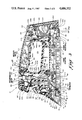
- FIG. 6 is top plan view of a soleplate assembly of the electronic pressing iron of FIG. 1 with the housing removed showing details of the location of various components mounted above a steam chest cover of the soleplate;
- FIG. 7 is a side elevational view of the soleplate and associated components shown in FIG. 5 having a fuse assembly removed in order to show details of a pair of power resistors;
- FIG. 8 is an enlarged fragmentary sectional view of a portion of a soleplate, taken generally along line 8--8 of FIG. 6, showing details of a temperature sensing thermistor mounted within the soleplate;
- FIG. 9 is an ennlarged fragmentary sectional view, taken generally along line 9--9 of FIG. 6, of a portion of the soleplate and the thermistor showing details of the location of an electric heating element and a steam chamber in relation to the thermistor;
- FIG. 10 is a schematic diagram of electronic control circuitry of the electronic pressing iron of FIG. 1;
- FIG. 11 is top plan view of the soleplate with the steam chest cover removed, showing details of the location of the elctric heating element, a plurality of steam passages and a thermistor well;
- FIG. 12 is a sectional view of a mercury switch taken generally along line 12--12 of FIG. 3.
- the electronic pressing iron 10 has a cast aluminum soleplate 12.
- the soleplate 12 has a bottom face or pressing surface 20 adapted to be placed in contact with a suitable fabric to be ironed.
- a plurality of open top labyrinthine steam passages 22 are formed on an upper side 23 of the soleplate 12 and are adapted to carry steam throughout the soleplate 12 and deliver the steam to a plurality of steam vents 24, two of which are shown in FIG. 3.
- the steam vents 24 open onto the pressing surface 20 and are particularly adapted to provide heated water vapor or steam to fabrics to be ironed in order to facilitate pressing.
- the steam is generated by an electric heating element 26, which is a conventional sheathed element and is formed within a rib 27 in the soleplate 12 in good heat transfer relationship with the pressing surface 20.
- the electric heating element 26 is adapted to dissipate 1250 watts of power at 120 volts.
- the electric heating element 26 supplies heat to the soleplate 12 and converts water to steam, the water being supplied from other portions of the iron.
- the steam passages 22 include a flash or steam chamber 28 into which water is dripped from a suitable source, as will be discussed hereinafter.
- a flash or steam chamber 28 into which water is dripped from a suitable source, as will be discussed hereinafter.
- the soleplate 12 defines a portion of the open top steam passages 22 which are enclosed by a sheet metal steam chest cover 32.
- the steam chest cover 32 extends across almost all of the soleplate 12 and forms a sealed enclosure with the exception of the steam vents 24.
- a room temperature vulcanizing compound seals the outer edges of the steam chest cover 32 to the soleplate 12 at a joint 35. Water is delivered to the steam chamber 28 through a steam chamber opening 34 in the steam chest cover 32.
- a pair of heating element terminals respectively numbered 36 and 38, as may best be seen in FIG. 6, are provided.
- the soleplate 12 includes a thermistor well 40 formed integral therewith between a rear wall 41 of a forward portion 41a of the rib 27 containing the heating element 26 and a forward portion 42 of the steam passages 22.
- the thermistor well 40 is adapted to receive a thermistor assembly 43, which will be described in further detail hereinafter.
- the thermistor assembly 43 is held within the well 40 in good heat conducting relationship with the soleplate 12 by a thermistor bracket 44, which is fastened by a screw 46 to the soleplate 12.
- a housing bracket 48 In order to secure the plastic housing 14 to the soleplate 12, a housing bracket 48, as best shown in FIGS. 2 and 5, is provided.
- the housing bracket 48 has a base portion 50 which is connected through the steam chest cover 32 to the soleplate 12 and held fixedly thereto by a plurality of screws 52.
- the housing bracket 48 has an aperture 54 which is in registry with the steam chamber opening 34 to allow water to flow into the steam chamber 28.
- the housing bracket 48 has a pair of upstanding leg portions 55 terminating at a pair of horizontal securing members 56 which are adapted for connection with the plastic housing 14 to secure it to the soleplate 12.
- Each of the horizontal securing members 56 has a sheet metal nut 58 interfitted therewith which receives an elongated screw 60 to hold the plastic housing 14 securely to the soleplate 12.
- the soleplate 12 also has connected thereto a resistor bracket 62 which is adapted to support a pair of 3000 ohm, 10 watt ceramic power resistors, respectively numbered 64 and 66, above the soleplate 12.
- An insulating sleeve 64a covers a lead from the power resistor 64.
- the resistor bracket 62 is affixed to the soleplate 12 by a threaded fastener 68 which threadedly engages a perforated mount 69 formed integral with a rear portion of the soleplate 12.
- a locator mount 69a, having a locator lip 69b, is also formed integral with the soleplate 12 and engates the bracket 62.
- the resistor bracket 62 has an arm section 70 having a rectangular cutout which receives a thermal fuse assembly 76 and holds it in spaced relation above the soleplate 12, as best shown in FIG. 6.
- the thermal fuse assembly 76 includes a fuse 77, an insulating sleeve 77a surrounding it and in supporting engagement with the arm section 70.
- a fuse lead 78 is electrically connected to the heating element terminal 38 and to the fuse 77.
- a heel bracket 80 is mounted by a pair of screws, respectively numbered 82 and 84, to a pair of perforated mounting blocks 85 formed integral with a rear portion of the soleplate 12.
- the heel bracket 80 includes a pair of engaging tail pieces 86 and 88 having respective apertures 90 and 92 formed therein for engagement with the phenolic lower housing 16 as will be discussed in greater detail hereinafter.
- the heel bracket 80 also includes an integral center tailpiece 93 having an aperture 93a formed therein.
- the phenolic lower housing 16 is mounted above the soleplate 12 in spaced relation therefrom and is secured to the heel bracket tailpieces 86 and 88 by a pair of screws 99 which engage the apertures 90 and 92 and the phenloic lower housing 16.
- the lower housing 16 has, at a forward end thereof, a tower neck 100 through which a pair of insulated electrical leads 102 and 104 from the thermistor assembly 43 which are connected to respective bare thermistor leads l02a and l04a which are partially covered by respective high temperature glass-filled dielectric sleeves l02b and l04b which protect the bare leads l02a and l04a.
- the electrical leads 102 and 104 pass through and into an upper handle assembly 105 of the electronic pressing iron 10.
- the upper handle assembly 105 comprises a portion of a forward column l05a.
- the phenolic lower housing 16 also includes a water valve seat 106 into which a valve stem and pilot 107 selectively extends to control flow of water from a water tank to the steam chamber 28.
- the valve stem and pilot 107 are actuated by a control knob l07a.
- a water delivery tube 108 extends from the valve seat 106.
- the water delivery tube 108 is connected to a brass injector 111 at a side injector fitting 111a.
- the brass injector 111 engages a washer 111b and is seated in the steam chamber opening 34 to deliver water to the steam chamber 28.
- An upper portion of the injector 111 is connected in seating engagement with a hollow tubular boss 111c and a washer 111d in an upper wall 112 of the phenolic lower housing 16.
- the upper wall 112 defines a bottom wall of a water tank 114 in the plastic housing 14.
- Other portions of the water tank 114 are defined by portions of the upper housing 18.
- a grommet 118 is fitted to the upper wall 112 for receipt of a plurality of conductive leads from the soleplate 12.
- the upper wall 112 is formed integral with a heel rest engaging member 120 at the rear portion of the iron and is in contact with a portion of the heel bracket 80.
- a sheet metal reflector 121 is connected to an underside of the upper wall 112 immediately above the power resistors 64 and 66 to minimize heat transfer from the power resistors to the plastic housing 14 and the electronic components contained therein.
- the phenolic lower housing 16 is sealed about its periphery to the thermoplastic polyester upper housing 18 by room temperature vulcanizing compound 122 to form the reservoir 114.
- room temperature vulcanizing compound 122 in order to hold the forward portions of the housing members 16 and 18 in engagement a plurality of threaded fasteners 123, one of which is shown, extends through the phenolic lower housing 16 to threadedly engage a sleeve 124 in the forward portion of the thermoplastic upper housing 18 immediately adjacent the water delivery tube 108.
- the upper housing 18 includes a tower 126 which is sealingly fitted to the tower cylinder 100 by a room temperature vulcanizing compound to protect from moisture the thermistor leads 102 and 104 which pass therethrough.
- a portion of the water tank 114 which is defined by a vertical wall section 128.
- a funnel section 130 forward of the tower 126 is a funnel section 130 into which water is poured in order to fill the water tank 114.
- the inner end of the funnel 130 is wider than the tower 126 so that water flows around the tower 126 in a manner well known in the prior art in order to fill the water tank 114.
- the thermistor leads 102 and 104 are protected from contact with water by the tower 126 and exit an upper section 132 of the tower 126 through a grommet 134.
- the thermistor leads 102 and 104 are connected to a combination potentiometer-switch 136 mounted in a handle portion 138 of the upper thermoplastic housing 18.
- the upper housing 18 includes a handle 137 comprised of a handle portion 138 and a handle cover 140 which is connected by a plurality of screws 142 to the handle portion 138.
- the handle 137 is connected to the forward column l05a and a rear column l42a.
- An escutcheon plate 143 having a pair of apertures l43a and l43b formed therein is fitted to the handle cover 140 and covers the screw 142.
- the upper housing 18 also includes an integral gripping portion 144 which partially defines an opening 146 through which an operator's fingers may pass to grip the handle 137.
- the gripping portion 144 and the handle cover 140 also, together with a forward wall section 148, define a chamber 150 in the handle 137 for receipt of printed circuit boards as will be described in more detail later.
- a control knob 160 is fitted to a stem 162 of the potentiometer-switch 136.
- the control knob 160 has a pointer l63a adapted to sweep past an indicating escutcheon plate l63b as is conventional in the art.
- an ON/OFF switch within the potentiometer-switch 136 is opened to switch the electronic pressing iron 10 off, as will be described in more detail hereinafter.
- the control knob 160 is rotated clockwise, the electronic pressing iron 10 is switched on and a temperature set point, selected by the potentiometer-switch 136, is raised with rotation, as will be described in further detail below.
- Pump controls for spraying water and providing instant extra steam are provided immediately adjacent the handle so that the operator need merely reach out with his thumb to actuate them.
- An instant extra steam button 164 and a water spray button 166 are provided on the top cover of the electronic pressing iron 10.
- the water spray button 166 when depressed, activates a bellows pump 168 which draws water through a tube 170 located in water tank 114 up into the bellows pump 168 and forces the water out through a spray delivery tube 180 which delivers the water to a spray head 182 mounted on a bracket 184 mounted on one of the walls defining the funnel 130.
- the instant extra steam button 164 when depressed, activates a bellows pump 190 which draws an extra charge of water from the water tank 114 and delivers it through a tube 194 to the boss lllb onto which the tube 194 is fitted.
- the water flows through the boss lllc and through the injector 111 into the steam chamber 28 where the extra charge of water is converted to steam which flows out of the steam vents 24.
- the spray and steam features are disclosed in detail in U.S. Pat. No. 4,398,364 to Augustine et al. for STEAM IRON the disclosure which is incorporated by reference herein.
- a pair of circular apertures are located immediately behind the instant extra steam and water spray buttons 164 and 166 in the handle.
- the apertures 200 and 202 receive respective light emitting diodes which provide a visual indication when the electronic pressing iron 10 is in various preselected states, as will be described in detail later on.
- the handle cover 140 terminates at a rear portion 210 to which is interfitted with a heel rest assembly 212.
- the heel rest assembly 212 comprises a rear cover plate 212a with a rear cover insert 212b connected thereto by a plurality of screws 212c.
- the rear cover plate 212a is connected to the housing 14 by a plurality of screws 212d which engage respective sheet metal nuts 212e, one of which engages the upper plastic housing 18, the other of which engages the tailpiece 120 of the lower phenolic housing 18.
- the heel rest assembly 212 has a power control printed circuit board 214 mounted between the rear cover plate 212a and the rear cover insert 212b.
- the power control printed circuit board 214 is electrically connected to the soleplate 12 and to a pair of printed circuit boards 216 and 218 mounted in the handle chamber 150.
- a slot 2l8a is defined in the rear portion of the iron to receive leads connecting circuit boards 216 and 218 to the circuit board 214.
- An adhesive backed escutcheon 219 is adhered to the rear cover insert 212b and covers over the heads of the screws 212c.
- a closure plate 220 is secured by a screw 220a to the center portion 93 of the heel bracket 80.
- the heating functions of the soleplate 12 are controlled by a combination power control circuit, temperature sensing circuit and motion and attitude sensing circuit 230 which include the printed circuit boards 214, 216 and 218 and which may best be seen in FIG. 10.
- Alternating current electric power is delivered to the electronic pressing iron 10 through a power cord 232 which is received by a strain relief 234 fitted through an aperture in the upper thermoplastic polyester housing 18 of the electronic pressing iron 10.
- the power cord 232 includes a lead 240 and a lead 242 adapted to receive 120 volt atternating current from a suitable source.
- a 22 kilohm dropping resistor 244 and a neon lamp 246 are connected in series across the leads 240 and 242 so that when the power cord 232 is plugged in, the neon lamp 246 is illuminated.
- the resistor 244 and the neon lamp 246 are connected to the printed circuit board 214.
- the neon lamp 246 is mounted in registry with an amber colored plastic window 250 mounted in a side of the upper thermoplastic housing 18 for easy observation as is shown in FIGS. 1 and 2.
- the electric heating element 26 which is connected in series with the thermal fuse 77 of thermal fuse assembly 76.
- a relay 252 having a solenoid 254 and a pair of power contacts 256 has the power contacts 256 connected between the heating element 26 and the lead 240 to control the flow of alternating current therethrough.
- the relay 252 is a Model JC1aF purchased from Aromat Corporation, Mountainside, N.J.
- a full-wave rectifier bridge 260 consisting of a plurality of diodes 262, 264, 266, and 268 is connected across the leads 240 and 242 and is mounted on the circuit board 214.
- a positive voltage direct current lead 270 is connected to a junction of the diodes 266 and 268.
- a ground lead 271 is connected to the junction of the diodes 262 and 264.
- Positive DC voltage is supplied by lead 270 to a single pole switch 272, which was previously described as part of the potentiometer-switch control 136.
- the other portion of the potentiometer-switch control 136 is a 100 kilohm, 20% taper potentiometer 274 which is mechanically connected to the single pole switch 272 and has a tap 275 connected to receive a positive 22 volt potential.
- the single pole switch 272 is connected to a lead 280 which feeds full wave rectified current to the power resistors 64 and 66 previously described.
- the power resistor 64 is connected to a 220 microfarad electrolytic smoothing capacitor 282 which is also connected to ground.
- a Zener diode 284 having a 22-volt Zener potential, is connected across the smoothing capacitor 282 and provides a regulated positive 22 volt potential plus or minus 2.2 volts to a lead 286.
- the lead 286 is connected to an 8.2 kilohm resistor 288 which is series connected to a 5.6 kilohm resistor 290 and a 1 kilohm grounded resistor 292.
- a junction 293 of the resistors 290 and 292 is connected to a 2N5064 silicon controlled rectifier or thyristor 294 at a gate 296.
- An anode 298 of the silicon controlled rectifier 294 is connected to the relay 254.
- the cathode 300 of the silicon controlled rectifier 294 is connected to ground.
- the relay solenoid 254 is also connected to the power resistor 66 to receive a 24 volt operating voltage.
- a 1N4004 diode 302 is connected in parallel with the relay solenoid 254 to prevent damage to the silicon controlled rectifier 294 when current flow is quickly interrupted.
- the diode 302 also provides a discharge path for the counter-EMF present across the relay 254 when the silicon controlled rectifier 294 switches off.
- the silicon controlled rectifier 294 controls the relay 252 which enables or disables the electric heating element 26.
- the silicon controlled rectifier 294 is, in turn, controlled by a temperature sensing circuit 310 which is enabled or disabled by an attitude and motion sensing circuit 312.
- the circuit includes a reference voltage divider 314 having a plurality of series connected resistors 316, 318, 320 and 322 which receive a positive 22 volt potential from the lead 286 at a terminal 321.
- the resistor 316 is a 47 kilohm resistor.
- the resistor 318 is a 9.1 kilohm resistor.
- the resistor 320 is a 6.8 kilohm resistor.
- the resistor 322 is a 47 kilohm resistor.
- the voltage divider 314 provides a plurality of stable, fixed reference voltages to other portions of the circuit.
- the positive 22 volt potential is also fed to the tap 275 of the potentiometer 274.
- the potentiometer 274 is connected in series with a PH65DIA thermistor 330 comprising a portion of the thermistor assembly 43 and which is connected in parallel with a 180 kilohm resistor 332 to linearize the response of the thermistor 330.
- the resistor 332 is connected in series with a 6.8 kilohm resistor 334 and a 10 kilohm calibrating potentiometer 336 having a tap 337.
- the tap 337 of the calibrating potentiometer 336 is connected to ground.
- the thermistor 330 is surrounded by a potting compound 338 which fills the thermistor well 40 and consists of a mixture of room temperature vulcanizing plastic and a good heat conductor.
- the potting compound 338 is obtained from the Dewey and Almy Chemical Division of W. R. Grace and Co., Canton, Mass., and is identified as ECCOSIL 4954.
- a ceramic insulator cap 339 which insulates the thermistor leads 102 and 104 electrically from the soleplate 12 and the steam chest cover 32, connects the insulated leads 102 and 104 to the bare conductors l02a and l04a which are enclosed in respective high temperature, glass filled, dielectric sleeves 102b and l04b extending through a pair of respective apertures 339a and 339b in the ceramic insulator cap 339. Additional room temperature vulcanizing compound covers the top of the ceramic insulator cap 339 to flexibly bond the sleeves l02b and l04b to the ceramic insulator cap 339. Temperature signals from the thermistor 330 are picked off by a lead 340 at a junction between the potentiometer 274 and the thermistor 330.
- the temperature signals from lead 340 are fed to an LM339N integrated circuit which comprises a plurality of comparators 349 including a comparator 350, a comparator 352 and a comparator 354.
- the comparators 350 and 354 together comprise a window comparator which functions solely to provide a signal to a Toshiba TLG147 green light emitting diode 356.
- the green light emitting diode 356 is mounted in registry with the aperture 202 and is connected to a 3.3 kilohm pullup resistor 358, which is energized by the positive 22 volt potential.
- the comparators 350 and 354 are adapted to simultaneously sink currents at their respective output terminals 360 and 364 only when the temperature signal received at their respective inverting input terminal 366 and noninverting input terminal 368 lies between the reference potentials supplied by the voltage divider 314 to a noninverting terminal 370 and an inverting terminal 372.
- the green light emitting diode 356 is only illuminated when the soleplate 12 is typically operating within a temperature of plus or minus thirty degrees Centigrade of the setpoint temperature selected by the potentiometer 274, indicating to the user that the soleplate 12 is at the selected temperature and that the electronic pressing iron 10 is ready to use.
- a 3.4 megohm resistor 390 is connected across its output terminal 380 and its noninverting terminal 374 to provide hysteresis in order to eliminate chatter of the relay 250.
- a 0.47 microfarad nonpolarized electrolytic capacitor 392 is connected across the input terminals 374 and 376 of the temperature control comparator 352 to bypass high frequency noise in order to prevent false switching of the temperature control comparator 352.
- the attitude sensing circuit 312 is provided.
- the attitude and motion sensing circuit includes a mercury switch 400 which senses both attitude and motion of the electronic pressing iron 10.
- the mercury switch 400 is mounted on the printed circuit board 216 in the handle 137 and oriented at an angle of 5.5 degrees plus or minus 0.5 degrees to the soleplate 12.
- the mercury switch 400 consists of a cylindrical metallic wall 400a having a circular end wall 400b formed integral therewith.
- a metallic conducting end cap 400c is connected to the cylindrical wall 400a opposite the end wall 400b and has a central aperture having an insulating plastic insert 400d held therein.
- a central electrode 400e passes through the insulator 400d and terminates in a cavity 400f defined by cylindrical wall 400a, cap 400c, insulator 400e and end wall 400b.
- the cylindrical wall 400a, the end wall 400b and the end cap 400c comprise a first contact.
- the central electrode 400e comprises a second contact.
- a quantity or pool of mercury 400g is confined within cavity 400f and is free to move about therein.
- a tangential electrical connector 400h is welded to the cylindrical wall 400a. It may be appreciated that the mercury switch 400 is closed when the quantity of mercury 400g creates a bridging connection between the electrode 400e and either end cap 400c, cylindrical wall 400aor end wall 400b. When such a connection is made, the capacitor 406 is rapidly discharged due to the shunting effect of the mercury droplet or pool 400g. It may also be appreciated that the mercury switch 400 is positioned within the iron so that the end wall 400b is slightly lower than the end cap 400c.
- the mercury switch 400 is relatively easy to position since the leads 400h and 400e confine it to the proper orientation with respect to the printed circuit board 216.
- the attitude sensing circuit 312 operates so that when the electronic pressing iron 10 is resting with its heel rest assembly 212 horizontal (in the "heel rest position"), the contacts of the mercury switch 400 are open. When the electronic pressing iron 10 is horizontal and is moving, the contacts of the mercury switch 400 are opening and closing as the mercury droplet 400g moves within the cavity 400f. When the electronic pressing iron 10 is resting with the soleplate 12 horizontal and the electronic pressing iron 10 is not moving, the contacts of the mercury switch 400 are closed.
- the collector 418 is connected to a lead 424.
- a comparator 426 having an inverting terminal 428, a noninverting terminal 430 and an output terminal 432 is connected at its output terminal 432 to a lead 434.
- a 2.2 megohm resistor 435 is connected between the output terminal 432 and the noninverting input terminal 430 to provide hysteresis to the comparator 426 and help prevent false switching.
- a 1.0 megohm resistor 435a and a 270 kilohm resistor 435b are series connected as a voltage divider between the 22 volt source of regulated potential and ground.
- a junction 435c, between the resistors 435a and 435b, is connected to the noninverting terminal 428 to supply a regulated reference voltage to it.
- the lead 424 is connected to the inverting terminal 428 to supply a timing voltage to it, as will become apparent hereinafter.
- the lead 434 is connected to a Toshiba TLG 147 red light emitting diode 436 which receives current through a 3.3 kilohm pullup resistor 438 from the lead 286.
- the red light emitting diode 436 is aligned in registry with the apertur 200 and indicates when the heating element 26 is not disabled.
- the red light emitting diode 436 is illuminated and a normal bias from the resistors 318 and 320 is supplied to the inverting terminal 376 of the temperature control comparator 352, allowing it to control the temperature of the soleplate 12 as previously described.
- the output terminal 432 goes high, the red light emitting diode 436 switches off, the inverting terminal 376 is driven high, pulling the output terminal 380 low and switching the silicon controlled rectifier 294 off regardless of the temperature of the soleplate 12.
- the attitude and motion sensing circuit 312 also includes a 22 microfarad electrolytic timing capacitor 446 having a 12 megohm bleeder resistor 448 connected in parallel with it. Both the timing capacitor 446 and the bleeder resistor 448 are connected between the lead 424 and ground. They are each also connected to the inverting terminal 428 of the comparator 426 to supply a timing voltage to it. Additionally, a 1N914 switching diode 450 and a 680 kilohm resistor 452 are connected in series to the lead 424 and to the collector 418 of the charging transistor 414. The resistor 452 is connected to a lead 454 which has the mercury switch 400 connected across it. The mercury switch 400 is also connected to ground and to the electrolytic capacitor 406.
- the transistor 414 In normal operation, when the electronic pressing iron 10 is first powered up, the transistor 414 is switched conducting by base current from the capacitors 406 and 408 as they initially charge up. The transistor 414 rapidly charges the timing capacitor 446 to full charge. In the event that the electronic pressing iron 10 is left with the soleplate 12 in a horizontal position or if the electronic pressing iron 10 is lying on its side l4a or l4b, the mercury switch 400 is closed and the timing capacitor 446 quickly discharges through the diode 450, the resistor 452 and the mercury switch 400.
- the timing capacitor 446 discharges in approximately 30 seconds, pulling the voltage of the lead 424 low, switching the output terminal 432 of the comparator 426 low, causing the output voltage of the temperature control comparator 352 to go low and interrupting any current that may be flowing to the silicon controlled rectifier 294.
- the mercury switch 400 remains open and the timing capacitor 446 discharges in approximately ten minutes through the bleeder resistor 448, again, switching comparator 426 low and comparator 352 to disable the silicon controlled rectifier 294.
- the mercury switch 400 intermittently opens and closes as a result of acceleration of the iron 10, causing the voltage at the lead 454 to vary in a pulse-like fashion due to the capacitor 406 being discharged and charged.
- These pulses are differentiated by the capacitor 408 and the resistor 410 and fed as extremely short pulses to the base 416, thereby switching transistor 414 on and provide bursts of charging current to the timing capacitor 446 from the resistor 422 to maintain it at a full charge.
- the electronic pressing iron 10 may be quickly and easily set at a desired temperature by the control knob 160. As the iron is heating up, the red light emitting diode 436 is illuminated to provide an indication to the user that the soleplate 12 is heating up but not yet ready for use. Once the soleplate 12 reaches operating temperature, the green light emitting diode 356 is illuminated, thereby indicating to the user that the electronic pressing iron 10 is ready for use.
- the electronic circuit 230 controls the temperature of the soleplate 12 to within ⁇ 5° Centigrade, and in particular because the thermistor 330 is located between the heating element 26 and the steam chamber 28, when the soleplate 12 is operating at low temperature setpoints, the addition of extra water to the flash chamber 28 when the instant extra steam button 164 is pressed will not cause the flash chamber 28 to drop below the steaming temperature, but rather any reduction in temperature will be rapidly sensed by the thermistor 330 which will cause the relay 252 to close, energizing the heating element 26 to insure that the soleplate 12 maintains the setpoint temperature.
- the electronic pressing iron 10 not only has accurate temperature control to prevent damaging delicate fabrics and provide uniform steaming, but also has the safety features of the motion and attitude circuit 312 whereby if the electronic pressing iron 10 ceases moving with the soleplate 12 in a horizontal position, electric power to the heating element 26 is interrupted within 30 seconds of iron movement ending. Should the iron be left unattended on its heel rest 212, electric power to the heating element 26 will be interrupted within 10 minutes after the iron is placed on its heel rest 212.
- the mercury switch 400 opens and closes, re-enabling the temperature control circuit 310, and causing the heating element 26 to re-energize.
- the timing capacitor 446 is recharged and the heating element 26 is re-enabled.
Landscapes
- Engineering & Computer Science (AREA)
- Textile Engineering (AREA)
- Irons (AREA)
Abstract
Description
Claims (23)
Priority Applications (5)
| Application Number | Priority Date | Filing Date | Title |
|---|---|---|---|
| US90/002926A US4686352B1 (en) | 1984-04-27 | 1984-04-27 | Electronic pressing iron |
| CA000471759A CA1229117A (en) | 1984-04-27 | 1985-01-09 | Electronic pressing iron |
| AU37921/85A AU3792185A (en) | 1984-04-27 | 1985-01-18 | Electronic pressing iron |
| GB08507099A GB2158105B (en) | 1984-04-27 | 1985-03-19 | Electronic pressing iron |
| DE19853512906 DE3512906A1 (en) | 1984-04-27 | 1985-04-11 | ELECTRIC IRON |
Applications Claiming Priority (1)
| Application Number | Priority Date | Filing Date | Title |
|---|---|---|---|
| US90/002926A US4686352B1 (en) | 1984-04-27 | 1984-04-27 | Electronic pressing iron |
Publications (2)
| Publication Number | Publication Date |
|---|---|
| US4686352A true US4686352A (en) | 1987-08-11 |
| US4686352B1 US4686352B1 (en) | 1993-12-14 |
Family
ID=24423674
Family Applications (1)
| Application Number | Title | Priority Date | Filing Date |
|---|---|---|---|
| US90/002926A Expired - Lifetime US4686352B1 (en) | 1984-04-27 | 1984-04-27 | Electronic pressing iron |
Country Status (5)
| Country | Link |
|---|---|
| US (1) | US4686352B1 (en) |
| AU (1) | AU3792185A (en) |
| CA (1) | CA1229117A (en) |
| DE (1) | DE3512906A1 (en) |
| GB (1) | GB2158105B (en) |
Cited By (62)
| Publication number | Priority date | Publication date | Assignee | Title |
|---|---|---|---|---|
| US4748755A (en) * | 1986-12-29 | 1988-06-07 | Sunbeam Corporation | Housing assembly for electric steaming and pressing iron |
| JPS63503020A (en) * | 1986-01-16 | 1988-11-02 | リミタ−・アクチエンゲゼルシャフト | safety cutting device |
| US4785197A (en) * | 1987-08-20 | 1988-11-15 | Pulse Electronics, Inc. | Tilt switch |
| US4833297A (en) * | 1985-06-07 | 1989-05-23 | Oficina De Investigacion Agrupada, S.A. | Improved arrangement in steam iron protection circuits |
| US4859869A (en) * | 1987-05-09 | 1989-08-22 | Braun Aktiengesellschaft | Safety switching means for controlling a current consumer |
| US4914721A (en) * | 1986-11-20 | 1990-04-03 | Ernst Peiniger Gmbh Unternehmen Fuer Bautenschutz | Safety device |
| US4939856A (en) * | 1989-09-25 | 1990-07-10 | Black & Decker Inc. | Adjustable steam flow control for an electric steam iron |
| US5010664A (en) * | 1988-11-18 | 1991-04-30 | Matsushita Electric Industrial Co., Ltd. | Steam iron having a solenoid driven pump and heated evaporation chamber for providing steam and operable for further providing extra steam at specified intervals |
| US5094021A (en) * | 1990-12-05 | 1992-03-10 | Chen Su Min | Ultrasonic iron |
| GB2274287A (en) * | 1993-05-10 | 1994-07-20 | Singer Co Nv | Steam ironing press |
| US5380983A (en) * | 1993-07-12 | 1995-01-10 | Black & Decker Inc. | Electrical appliance having user proximity sensor |
| US5463205A (en) * | 1994-05-19 | 1995-10-31 | Pentalpha Enterprises Ltd. | Photosensitive switching apparatus for an electric appliance |
| US5602429A (en) * | 1994-04-09 | 1997-02-11 | Braun Aktiengesellschaft | Safety shut-off device |
| USD389622S (en) | 1996-12-04 | 1998-01-20 | Sunbeam Products, Inc. | Steam iron |
| USD389969S (en) | 1996-12-04 | 1998-01-27 | Sunbeam Products, Inc. | Dry iron |
| US5747778A (en) * | 1996-01-05 | 1998-05-05 | Liu; Jung-Yang | Hot melting iron having a safety control circuit board |
| US5799420A (en) * | 1997-01-10 | 1998-09-01 | Black & Decker Inc. | Steam iron water tank with air trap and gear mounts |
| US5818011A (en) * | 1995-03-31 | 1998-10-06 | Matsushita Electric Industrial Co., Ltd. | Electrically controlled iron for pressing clothing and textiles with automatic shutoff function |
| US5844203A (en) * | 1995-10-06 | 1998-12-01 | Black & Decker Inc. | Combined switch actuator and signal light transmitter for an iron |
| US5852279A (en) * | 1996-10-02 | 1998-12-22 | Windmere Corporation | Clothes iron with automatic shut off system controlled by multiple switches |
| US6104009A (en) * | 1998-12-07 | 2000-08-15 | Hp Intellectual Corp. | Electrical appliance having user proximity sensor |
| US6151815A (en) * | 1998-01-23 | 2000-11-28 | Seb S.A. | Water reservoir for a steam iron, and method for producing such a reservoir |
| CN1072292C (en) * | 1993-04-23 | 2001-10-03 | 幕林克斯公司 | Iron and making of same |
| US6307182B1 (en) | 1997-04-25 | 2001-10-23 | Toastmaster, Inc. | Electric appliance having a proximity sensor |
| US6384379B1 (en) * | 1998-01-09 | 2002-05-07 | Gerd Reime | Protective device for an iron and iron incorporating same |
| US6429410B1 (en) * | 1997-11-08 | 2002-08-06 | Robert Bosch Gmbh | Circuit for heating a component |
| US6581309B1 (en) * | 2001-12-07 | 2003-06-24 | Carl J. Conforti | Clothes iron |
| US20040133295A1 (en) * | 2002-09-30 | 2004-07-08 | Conair Corporation | Controller and method for a fabric grooming device |
| US20050158684A1 (en) * | 2004-01-15 | 2005-07-21 | Bussman Wesley R. | Remote staged furnace burner configurations and methods |
| US20050158681A1 (en) * | 2004-01-15 | 2005-07-21 | Bussman Wesley R. | Remote staged radiant wall furnace burner configurations and methods |
| WO2005050340A3 (en) * | 2003-10-22 | 2005-09-01 | Karlsruhe Forschzent | Otion-sensitive electronic circuit for activating or deactivating an electrically operated device |
| US20060076341A1 (en) * | 2004-10-08 | 2006-04-13 | Lozinski Gerald J | Pop-up auto-shutoff indicator for electric pressing irons |
| US20060081588A1 (en) * | 2004-10-05 | 2006-04-20 | Bowser John O | Electric pressing iron with user interface |
| US20060086712A1 (en) * | 2004-10-25 | 2006-04-27 | Feldmeier David C | Safety device for flat irons based on optical motion detection |
| US20060196090A1 (en) * | 2003-03-03 | 2006-09-07 | Dominique Gelus | Steam iron with a plastic skirt surrounding the steam chamber |
| US20090084770A1 (en) * | 2007-09-27 | 2009-04-02 | Mei-Yueh Huang | Device to detect the position of an iron |
| US20090166348A1 (en) * | 2007-12-28 | 2009-07-02 | Tsann Kuen (China) Enterprise Co., Ltd | Method and device for controlling an iron |
| US20100064557A1 (en) * | 2008-09-17 | 2010-03-18 | Xiaotian (Zhongshan) Industrial Co., Ltd. | Steam iron |
| US20100242314A1 (en) * | 2009-03-31 | 2010-09-30 | Freescale Semiconductor, Inc | Steam iron with acceleration and tilt detection |
| US20100257761A1 (en) * | 2009-04-08 | 2010-10-14 | Lung Wai Choi | Electric iron with a synchronizing temperature display |
| US20110089039A1 (en) * | 2009-10-16 | 2011-04-21 | Michael Nashner | Sub-Surface Marking of Product Housings |
| US20110089067A1 (en) * | 2009-10-16 | 2011-04-21 | Scott Matthew S | Sub-Surface Marking of Product Housings |
| US20110088924A1 (en) * | 2009-10-16 | 2011-04-21 | Michael Nashner | Sub-surface marking of product housings |
| US20130327759A1 (en) * | 2011-03-24 | 2013-12-12 | Panasonic Corporation | Iron |
| US8879266B2 (en) | 2012-05-24 | 2014-11-04 | Apple Inc. | Thin multi-layered structures providing rigidity and conductivity |
| US9173336B2 (en) | 2009-05-19 | 2015-10-27 | Apple Inc. | Techniques for marking product housings |
| US9185835B2 (en) | 2008-06-08 | 2015-11-10 | Apple Inc. | Techniques for marking product housings |
| US9280183B2 (en) | 2011-04-01 | 2016-03-08 | Apple Inc. | Advanced techniques for bonding metal to plastic |
| US9314871B2 (en) | 2013-06-18 | 2016-04-19 | Apple Inc. | Method for laser engraved reflective surface structures |
| US20160161107A1 (en) * | 2013-07-25 | 2016-06-09 | Koninklijke Philips N.V. | Apparatus for generating steam |
| US9434197B2 (en) | 2013-06-18 | 2016-09-06 | Apple Inc. | Laser engraved reflective surface structures |
| US10071584B2 (en) | 2012-07-09 | 2018-09-11 | Apple Inc. | Process for creating sub-surface marking on plastic parts |
| US10071583B2 (en) | 2009-10-16 | 2018-09-11 | Apple Inc. | Marking of product housings |
| US10220602B2 (en) | 2011-03-29 | 2019-03-05 | Apple Inc. | Marking of fabric carrying case for a portable electronic device |
| WO2019224568A3 (en) * | 2018-05-19 | 2020-05-28 | خالد سبتان | Protection against hazards and problems of irons |
| US10781551B2 (en) * | 2017-12-05 | 2020-09-22 | Tsann Kuen (Zhangzhou) Enterprise Co., Ltd. | Steam iron |
| CN113699768A (en) * | 2021-08-30 | 2021-11-26 | 惠州拓邦电气技术有限公司 | Automatic control method and device for electric iron and electric iron |
| US11208758B2 (en) * | 2017-08-01 | 2021-12-28 | Cricut, Inc. | Heat press |
| US11286612B2 (en) * | 2019-09-05 | 2022-03-29 | Hamilton Beach Brands, Inc. | Iron with heat control display on handle |
| US11945245B2 (en) | 2019-08-18 | 2024-04-02 | Cricut, Inc. | Heat press, components, apparatuses, systems, and methods |
| US12324114B2 (en) | 2021-09-24 | 2025-06-03 | Apple Inc. | Laser-marked electronic device housings |
| US12389974B2 (en) | 2022-03-03 | 2025-08-19 | Cricut, Inc. | Heat press apparatuses, systems, and methods |
Families Citing this family (20)
| Publication number | Priority date | Publication date | Assignee | Title |
|---|---|---|---|---|
| IT210802Z2 (en) * | 1985-12-05 | 1989-01-11 | Elettrodomus Spa | ELECTRIC STRENGTH IRON OF THE SO-CALLED TYPE WITHOUT CORD |
| FR2591246B1 (en) * | 1985-12-06 | 1988-07-08 | Labo Electronique Physique | ELECTRIC IRON WITH AN AUTOMATIC SAFETY DEVICE |
| US4745260A (en) * | 1986-01-22 | 1988-05-17 | Black & Decker Inc. | Automatic switching apparatus for an electric appliance |
| CA1262378A (en) * | 1986-01-22 | 1989-10-17 | Harry Albinger, Jr. | Automatic switching apparatus for an electrical appliance |
| FR2593637A1 (en) * | 1986-01-29 | 1987-07-31 | Seb Sa | Safety device to ensure the automatic cutting of the electrical supply to a mobile heating appliance, in particular an iron |
| US4692589A (en) * | 1986-02-05 | 1987-09-08 | Hamilton Beach Inc. | Electric iron having safety cutoff switch and temperature indicator |
| US4673798A (en) * | 1986-04-02 | 1987-06-16 | John Zink Company | Dual temperature electric curling iron having a safety shut-off circuit |
| US4727240A (en) * | 1986-08-11 | 1988-02-23 | Black & Decker Inc. | Electric iron with dual automatic cutoff |
| IT211107Z2 (en) * | 1986-09-25 | 1989-02-13 | Elvio Bernardi | SAFETY DEVICE FOR FERRIDA IRON IN GENERAL |
| DE3800921A1 (en) * | 1988-01-14 | 1989-07-27 | Joseph Dikoff | WIRELESS IRON |
| CH674657A5 (en) * | 1988-02-04 | 1990-06-29 | Jura Elektroapparate Fab | Intrinsically safe electric iron - with centre of gravity turning heating plate away from horizontal position |
| DE3937766A1 (en) * | 1989-11-14 | 1991-05-16 | Braun Ag | IRON WITH AN ELECTRICALLY HEATED IRON SOLE |
| IT1240471B (en) * | 1990-06-01 | 1993-12-17 | Nida S.R.L. | STEAM IRON, PERFECTED. |
| DE4117355A1 (en) * | 1991-05-28 | 1992-12-03 | Jola Spezialschalter K Mattil | Position responsive switch for electrical appts. - using non-metallic, electrically-conducting liquid for bridging spaced electrodes in switched tube |
| DE9106526U1 (en) * | 1991-05-28 | 1991-09-19 | Jola Spezialschalter K. Mattil & Co., 67466 Lambrecht | Position switch |
| ES2036934B1 (en) * | 1991-10-07 | 1996-07-01 | Fagor S Coop Ltda | "SAFETY SWITCHING DEVICE FOR ELECTRIC PLATES" |
| DE4218560C2 (en) * | 1992-06-05 | 1994-04-21 | Gustav Hahn | Switching device |
| US5493089A (en) * | 1994-01-13 | 1996-02-20 | Black & Decker Inc. | On/off switch assembly for an electric iron |
| DE29707453U1 (en) * | 1997-04-24 | 1997-06-26 | Lebsanft, Willy, 72669 Unterensingen | Ironing device |
| FR3070405B1 (en) * | 2017-08-31 | 2019-08-23 | Seb S.A. | IRON CONTAINING AN HOUSING, A HEATING BODY AND A FUNCTIONAL PLATINUM INTERPOSED BETWEEN THE HEATING BODY AND THE HOUSING |
Citations (27)
| Publication number | Priority date | Publication date | Assignee | Title |
|---|---|---|---|---|
| US1458418A (en) * | 1922-03-06 | 1923-06-12 | Clarence L Johnston | Safety device and switch |
| US2382587A (en) * | 1942-06-12 | 1945-08-14 | Albert G Thomas | Electric iron |
| US2778913A (en) * | 1954-10-06 | 1957-01-22 | Gen Electric | Temperature control and signal circuit |
| US2833903A (en) * | 1956-02-16 | 1958-05-06 | Robert L Waddell | Fully automatic electric iron |
| US2880531A (en) * | 1955-10-10 | 1959-04-07 | Proctor Mfg Corp | Flatiron |
| CH396245A (en) * | 1963-02-02 | 1965-07-31 | Schaer Hans | Electric steam iron |
| GB1068419A (en) * | 1964-10-08 | 1967-05-10 | Richards Morphy N I Ltd | Improvements relating to heat controlled electric smoothing irons |
| US3424894A (en) * | 1965-10-22 | 1969-01-28 | Arthur Schwartz | Electric iron and safety device therefor |
| US3492459A (en) * | 1966-12-30 | 1970-01-27 | Arthur Schwartz | Electric iron and safety device therefor |
| US3553429A (en) * | 1968-11-18 | 1971-01-05 | Eastman Kodak Co | Temperature control circuit |
| US3732394A (en) * | 1970-02-19 | 1973-05-08 | Issaac Braithwaite & Son Engin | Iron |
| US4130955A (en) * | 1976-06-16 | 1978-12-26 | Baumgartner Erich R | Pressing or smoothing iron comprising a safety turn-off means located in a heating current circuit |
| DE2750545A1 (en) * | 1977-11-11 | 1979-05-17 | Braun Ag | CONTROL CIRCUIT FOR IRON WITH A SENSOR RESISTANCE RESPECTIVE TO THE TEMPERATURE OF THE IRON HEATING |
| GB2009971A (en) * | 1977-11-11 | 1979-06-20 | Braun Ag | Flat-Iron with an Automatic Control System |
| GB2016051A (en) * | 1978-01-11 | 1979-09-19 | Dokoupil J | Ironing devices |
| US4203101A (en) * | 1977-01-11 | 1980-05-13 | Towsend Marvin S | Electric power interrupting apparatus |
| US4240217A (en) * | 1977-12-21 | 1980-12-23 | Seb S.A. | Electric steam iron |
| US4261120A (en) * | 1978-06-20 | 1981-04-14 | Scovill Inc. | Electric pressing iron having indicating ready light with improved switch means |
| DE2944242A1 (en) * | 1979-11-02 | 1981-05-14 | Robert 8021 Neuried Weigl | Smoothing iron incorporating electronic control circuits in handle - and having dropping resistor on sole to utilise heat output |
| US4347428A (en) * | 1979-08-27 | 1982-08-31 | Rowenta-Werke Gmbh | Handle and supporting structure for an electric pressing iron having electronic temperature control |
| WO1982003520A1 (en) * | 1981-04-07 | 1982-10-14 | Robert C Franklin | Appliance non-use detection safety power shut-off system |
| US4398364A (en) * | 1981-07-14 | 1983-08-16 | Sunbeam Corporation | Steam iron |
| JPS5914898A (en) * | 1982-07-19 | 1984-01-25 | 松下電器産業株式会社 | Iron |
| JPS5914899A (en) * | 1982-07-19 | 1984-01-25 | 松下電器産業株式会社 | iron |
| US4449035A (en) * | 1981-04-07 | 1984-05-15 | Seb S. A. | Arrangement for mounting a thermistor-type temperature sensor in a metallic heating device |
| US4455473A (en) * | 1981-04-10 | 1984-06-19 | Seb S.A. | Heat dissipator for the electronic circuit of a laundry iron |
| US4520257A (en) * | 1983-02-02 | 1985-05-28 | Seb S.A. | Electronic non-use power interruption safety device for an electric flat-iron |
Family Cites Families (1)
| Publication number | Priority date | Publication date | Assignee | Title |
|---|---|---|---|---|
| DE1246903B (en) * | 1964-07-01 | 1967-08-10 | Licentia Gmbh | Electric iron, preferably with a temperature controller |
-
1984
- 1984-04-27 US US90/002926A patent/US4686352B1/en not_active Expired - Lifetime
-
1985
- 1985-01-09 CA CA000471759A patent/CA1229117A/en not_active Expired
- 1985-01-18 AU AU37921/85A patent/AU3792185A/en not_active Abandoned
- 1985-03-19 GB GB08507099A patent/GB2158105B/en not_active Expired
- 1985-04-11 DE DE19853512906 patent/DE3512906A1/en not_active Ceased
Patent Citations (28)
| Publication number | Priority date | Publication date | Assignee | Title |
|---|---|---|---|---|
| US1458418A (en) * | 1922-03-06 | 1923-06-12 | Clarence L Johnston | Safety device and switch |
| US2382587A (en) * | 1942-06-12 | 1945-08-14 | Albert G Thomas | Electric iron |
| US2778913A (en) * | 1954-10-06 | 1957-01-22 | Gen Electric | Temperature control and signal circuit |
| US2880531A (en) * | 1955-10-10 | 1959-04-07 | Proctor Mfg Corp | Flatiron |
| US2833903A (en) * | 1956-02-16 | 1958-05-06 | Robert L Waddell | Fully automatic electric iron |
| CH396245A (en) * | 1963-02-02 | 1965-07-31 | Schaer Hans | Electric steam iron |
| GB1068419A (en) * | 1964-10-08 | 1967-05-10 | Richards Morphy N I Ltd | Improvements relating to heat controlled electric smoothing irons |
| US3424894A (en) * | 1965-10-22 | 1969-01-28 | Arthur Schwartz | Electric iron and safety device therefor |
| US3492459A (en) * | 1966-12-30 | 1970-01-27 | Arthur Schwartz | Electric iron and safety device therefor |
| US3553429A (en) * | 1968-11-18 | 1971-01-05 | Eastman Kodak Co | Temperature control circuit |
| US3732394A (en) * | 1970-02-19 | 1973-05-08 | Issaac Braithwaite & Son Engin | Iron |
| US4130955A (en) * | 1976-06-16 | 1978-12-26 | Baumgartner Erich R | Pressing or smoothing iron comprising a safety turn-off means located in a heating current circuit |
| US4203101A (en) * | 1977-01-11 | 1980-05-13 | Towsend Marvin S | Electric power interrupting apparatus |
| GB2009973A (en) * | 1977-11-11 | 1979-06-20 | Braun Ag | Control circuit for flat-irons |
| GB2009971A (en) * | 1977-11-11 | 1979-06-20 | Braun Ag | Flat-Iron with an Automatic Control System |
| DE2750545A1 (en) * | 1977-11-11 | 1979-05-17 | Braun Ag | CONTROL CIRCUIT FOR IRON WITH A SENSOR RESISTANCE RESPECTIVE TO THE TEMPERATURE OF THE IRON HEATING |
| US4240217A (en) * | 1977-12-21 | 1980-12-23 | Seb S.A. | Electric steam iron |
| GB2016051A (en) * | 1978-01-11 | 1979-09-19 | Dokoupil J | Ironing devices |
| US4261120A (en) * | 1978-06-20 | 1981-04-14 | Scovill Inc. | Electric pressing iron having indicating ready light with improved switch means |
| US4347428A (en) * | 1979-08-27 | 1982-08-31 | Rowenta-Werke Gmbh | Handle and supporting structure for an electric pressing iron having electronic temperature control |
| DE2944242A1 (en) * | 1979-11-02 | 1981-05-14 | Robert 8021 Neuried Weigl | Smoothing iron incorporating electronic control circuits in handle - and having dropping resistor on sole to utilise heat output |
| WO1982003520A1 (en) * | 1981-04-07 | 1982-10-14 | Robert C Franklin | Appliance non-use detection safety power shut-off system |
| US4449035A (en) * | 1981-04-07 | 1984-05-15 | Seb S. A. | Arrangement for mounting a thermistor-type temperature sensor in a metallic heating device |
| US4455473A (en) * | 1981-04-10 | 1984-06-19 | Seb S.A. | Heat dissipator for the electronic circuit of a laundry iron |
| US4398364A (en) * | 1981-07-14 | 1983-08-16 | Sunbeam Corporation | Steam iron |
| JPS5914898A (en) * | 1982-07-19 | 1984-01-25 | 松下電器産業株式会社 | Iron |
| JPS5914899A (en) * | 1982-07-19 | 1984-01-25 | 松下電器産業株式会社 | iron |
| US4520257A (en) * | 1983-02-02 | 1985-05-28 | Seb S.A. | Electronic non-use power interruption safety device for an electric flat-iron |
Cited By (83)
| Publication number | Priority date | Publication date | Assignee | Title |
|---|---|---|---|---|
| US4833297A (en) * | 1985-06-07 | 1989-05-23 | Oficina De Investigacion Agrupada, S.A. | Improved arrangement in steam iron protection circuits |
| JPS63503020A (en) * | 1986-01-16 | 1988-11-02 | リミタ−・アクチエンゲゼルシャフト | safety cutting device |
| US5039843A (en) * | 1986-01-16 | 1991-08-13 | Limitor Ag | Safety cutout device |
| US4914721A (en) * | 1986-11-20 | 1990-04-03 | Ernst Peiniger Gmbh Unternehmen Fuer Bautenschutz | Safety device |
| US4748755A (en) * | 1986-12-29 | 1988-06-07 | Sunbeam Corporation | Housing assembly for electric steaming and pressing iron |
| US4859869A (en) * | 1987-05-09 | 1989-08-22 | Braun Aktiengesellschaft | Safety switching means for controlling a current consumer |
| US4785197A (en) * | 1987-08-20 | 1988-11-15 | Pulse Electronics, Inc. | Tilt switch |
| US5010664A (en) * | 1988-11-18 | 1991-04-30 | Matsushita Electric Industrial Co., Ltd. | Steam iron having a solenoid driven pump and heated evaporation chamber for providing steam and operable for further providing extra steam at specified intervals |
| US4939856A (en) * | 1989-09-25 | 1990-07-10 | Black & Decker Inc. | Adjustable steam flow control for an electric steam iron |
| US5094021A (en) * | 1990-12-05 | 1992-03-10 | Chen Su Min | Ultrasonic iron |
| CN1072292C (en) * | 1993-04-23 | 2001-10-03 | 幕林克斯公司 | Iron and making of same |
| GB2274287A (en) * | 1993-05-10 | 1994-07-20 | Singer Co Nv | Steam ironing press |
| GB2274287B (en) * | 1993-05-10 | 1995-01-18 | Singer Co Nv | Steam ironing press |
| US5380983A (en) * | 1993-07-12 | 1995-01-10 | Black & Decker Inc. | Electrical appliance having user proximity sensor |
| US5602429A (en) * | 1994-04-09 | 1997-02-11 | Braun Aktiengesellschaft | Safety shut-off device |
| US5463205A (en) * | 1994-05-19 | 1995-10-31 | Pentalpha Enterprises Ltd. | Photosensitive switching apparatus for an electric appliance |
| US5595672A (en) * | 1994-05-19 | 1997-01-21 | Pentalpha Enterprises Ltd. | Automatic power interrupting apparatus for an electric appliance |
| US5818011A (en) * | 1995-03-31 | 1998-10-06 | Matsushita Electric Industrial Co., Ltd. | Electrically controlled iron for pressing clothing and textiles with automatic shutoff function |
| US5844203A (en) * | 1995-10-06 | 1998-12-01 | Black & Decker Inc. | Combined switch actuator and signal light transmitter for an iron |
| US5747778A (en) * | 1996-01-05 | 1998-05-05 | Liu; Jung-Yang | Hot melting iron having a safety control circuit board |
| US5852279A (en) * | 1996-10-02 | 1998-12-22 | Windmere Corporation | Clothes iron with automatic shut off system controlled by multiple switches |
| USD389622S (en) | 1996-12-04 | 1998-01-20 | Sunbeam Products, Inc. | Steam iron |
| USD389969S (en) | 1996-12-04 | 1998-01-27 | Sunbeam Products, Inc. | Dry iron |
| US5799420A (en) * | 1997-01-10 | 1998-09-01 | Black & Decker Inc. | Steam iron water tank with air trap and gear mounts |
| US6307182B1 (en) | 1997-04-25 | 2001-10-23 | Toastmaster, Inc. | Electric appliance having a proximity sensor |
| US6429410B1 (en) * | 1997-11-08 | 2002-08-06 | Robert Bosch Gmbh | Circuit for heating a component |
| US6384379B1 (en) * | 1998-01-09 | 2002-05-07 | Gerd Reime | Protective device for an iron and iron incorporating same |
| US6151815A (en) * | 1998-01-23 | 2000-11-28 | Seb S.A. | Water reservoir for a steam iron, and method for producing such a reservoir |
| US6104009A (en) * | 1998-12-07 | 2000-08-15 | Hp Intellectual Corp. | Electrical appliance having user proximity sensor |
| US6581309B1 (en) * | 2001-12-07 | 2003-06-24 | Carl J. Conforti | Clothes iron |
| US20040133295A1 (en) * | 2002-09-30 | 2004-07-08 | Conair Corporation | Controller and method for a fabric grooming device |
| US20060196090A1 (en) * | 2003-03-03 | 2006-09-07 | Dominique Gelus | Steam iron with a plastic skirt surrounding the steam chamber |
| WO2005050340A3 (en) * | 2003-10-22 | 2005-09-01 | Karlsruhe Forschzent | Otion-sensitive electronic circuit for activating or deactivating an electrically operated device |
| US7153129B2 (en) | 2004-01-15 | 2006-12-26 | John Zink Company, Llc | Remote staged furnace burner configurations and methods |
| US7025590B2 (en) | 2004-01-15 | 2006-04-11 | John Zink Company, Llc | Remote staged radiant wall furnace burner configurations and methods |
| US20050158681A1 (en) * | 2004-01-15 | 2005-07-21 | Bussman Wesley R. | Remote staged radiant wall furnace burner configurations and methods |
| US20050158684A1 (en) * | 2004-01-15 | 2005-07-21 | Bussman Wesley R. | Remote staged furnace burner configurations and methods |
| US20060081588A1 (en) * | 2004-10-05 | 2006-04-20 | Bowser John O | Electric pressing iron with user interface |
| US20060081589A1 (en) * | 2004-10-05 | 2006-04-20 | Chen Chi-Ting | Electric pressing iron with ready light and pop-up power switch |
| US20060076341A1 (en) * | 2004-10-08 | 2006-04-13 | Lozinski Gerald J | Pop-up auto-shutoff indicator for electric pressing irons |
| US20060086712A1 (en) * | 2004-10-25 | 2006-04-27 | Feldmeier David C | Safety device for flat irons based on optical motion detection |
| US20090084770A1 (en) * | 2007-09-27 | 2009-04-02 | Mei-Yueh Huang | Device to detect the position of an iron |
| US20090166348A1 (en) * | 2007-12-28 | 2009-07-02 | Tsann Kuen (China) Enterprise Co., Ltd | Method and device for controlling an iron |
| US9185835B2 (en) | 2008-06-08 | 2015-11-10 | Apple Inc. | Techniques for marking product housings |
| US8141278B2 (en) * | 2008-09-17 | 2012-03-27 | Xiaotian (Zhongshan) Industrial Co., Ltd. | Steam iron |
| WO2010031256A1 (en) * | 2008-09-17 | 2010-03-25 | 小田(中山)实业有限公司 | Steam iron |
| US20100064557A1 (en) * | 2008-09-17 | 2010-03-18 | Xiaotian (Zhongshan) Industrial Co., Ltd. | Steam iron |
| US20100242314A1 (en) * | 2009-03-31 | 2010-09-30 | Freescale Semiconductor, Inc | Steam iron with acceleration and tilt detection |
| US8091257B2 (en) * | 2009-03-31 | 2012-01-10 | Freescale Semiconductor, Inc. | Steam iron with acceleration and tilt detection |
| US20100257761A1 (en) * | 2009-04-08 | 2010-10-14 | Lung Wai Choi | Electric iron with a synchronizing temperature display |
| US9173336B2 (en) | 2009-05-19 | 2015-10-27 | Apple Inc. | Techniques for marking product housings |
| US8809733B2 (en) * | 2009-10-16 | 2014-08-19 | Apple Inc. | Sub-surface marking of product housings |
| US20110088924A1 (en) * | 2009-10-16 | 2011-04-21 | Michael Nashner | Sub-surface marking of product housings |
| US9962788B2 (en) | 2009-10-16 | 2018-05-08 | Apple Inc. | Sub-surface marking of product housings |
| US20110089067A1 (en) * | 2009-10-16 | 2011-04-21 | Scott Matthew S | Sub-Surface Marking of Product Housings |
| US20110089039A1 (en) * | 2009-10-16 | 2011-04-21 | Michael Nashner | Sub-Surface Marking of Product Housings |
| US9845546B2 (en) | 2009-10-16 | 2017-12-19 | Apple Inc. | Sub-surface marking of product housings |
| US10071583B2 (en) | 2009-10-16 | 2018-09-11 | Apple Inc. | Marking of product housings |
| US20130327759A1 (en) * | 2011-03-24 | 2013-12-12 | Panasonic Corporation | Iron |
| CN105568652B (en) * | 2011-03-24 | 2017-12-05 | 松下电器产业株式会社 | Flatiron |
| CN105568652A (en) * | 2011-03-24 | 2016-05-11 | 松下电器产业株式会社 | Iron |
| US10220602B2 (en) | 2011-03-29 | 2019-03-05 | Apple Inc. | Marking of fabric carrying case for a portable electronic device |
| US9280183B2 (en) | 2011-04-01 | 2016-03-08 | Apple Inc. | Advanced techniques for bonding metal to plastic |
| US8879266B2 (en) | 2012-05-24 | 2014-11-04 | Apple Inc. | Thin multi-layered structures providing rigidity and conductivity |
| US11597226B2 (en) | 2012-07-09 | 2023-03-07 | Apple Inc. | Process for creating sub-surface marking on plastic parts |
| US10071584B2 (en) | 2012-07-09 | 2018-09-11 | Apple Inc. | Process for creating sub-surface marking on plastic parts |
| US9314871B2 (en) | 2013-06-18 | 2016-04-19 | Apple Inc. | Method for laser engraved reflective surface structures |
| US9434197B2 (en) | 2013-06-18 | 2016-09-06 | Apple Inc. | Laser engraved reflective surface structures |
| US20160161108A1 (en) * | 2013-07-25 | 2016-06-09 | Koninklijke Philips N.V. | Apparatus for generating steam |
| US10234134B2 (en) * | 2013-07-25 | 2019-03-19 | Koninklijke Philips N.V. | Apparatus for generating steam |
| US10422521B2 (en) * | 2013-07-25 | 2019-09-24 | Koninklijke Philips N.V. | Apparatus for generating system |
| US20160161107A1 (en) * | 2013-07-25 | 2016-06-09 | Koninklijke Philips N.V. | Apparatus for generating steam |
| US11905646B2 (en) | 2017-08-01 | 2024-02-20 | Cricut, Inc. | Heat press |
| US12152338B2 (en) | 2017-08-01 | 2024-11-26 | Cricut, Inc. | Heat press |
| US11208758B2 (en) * | 2017-08-01 | 2021-12-28 | Cricut, Inc. | Heat press |
| US10781551B2 (en) * | 2017-12-05 | 2020-09-22 | Tsann Kuen (Zhangzhou) Enterprise Co., Ltd. | Steam iron |
| WO2019224568A3 (en) * | 2018-05-19 | 2020-05-28 | خالد سبتان | Protection against hazards and problems of irons |
| US11945245B2 (en) | 2019-08-18 | 2024-04-02 | Cricut, Inc. | Heat press, components, apparatuses, systems, and methods |
| US11286612B2 (en) * | 2019-09-05 | 2022-03-29 | Hamilton Beach Brands, Inc. | Iron with heat control display on handle |
| CN113699768B (en) * | 2021-08-30 | 2024-02-02 | 惠州拓邦电气技术有限公司 | Automatic control method and device for electric iron and electric iron |
| CN113699768A (en) * | 2021-08-30 | 2021-11-26 | 惠州拓邦电气技术有限公司 | Automatic control method and device for electric iron and electric iron |
| US12324114B2 (en) | 2021-09-24 | 2025-06-03 | Apple Inc. | Laser-marked electronic device housings |
| US12389974B2 (en) | 2022-03-03 | 2025-08-19 | Cricut, Inc. | Heat press apparatuses, systems, and methods |
Also Published As
| Publication number | Publication date |
|---|---|
| GB8507099D0 (en) | 1985-04-24 |
| GB2158105B (en) | 1987-07-22 |
| DE3512906A1 (en) | 1986-01-02 |
| CA1229117A (en) | 1987-11-10 |
| GB2158105A (en) | 1985-11-06 |
| US4686352B1 (en) | 1993-12-14 |
| AU3792185A (en) | 1985-10-31 |
Similar Documents
| Publication | Publication Date | Title |
|---|---|---|
| US4686352A (en) | Electronic pressing iron | |
| US4418268A (en) | Soldering iron holder with ready indicator and safety shutoff | |
| US4347428A (en) | Handle and supporting structure for an electric pressing iron having electronic temperature control | |
| US3745676A (en) | Cordless iron apparatus | |
| US6452501B1 (en) | Automatic shut-off and indication device for an electric heating appliance and electric pressing iron comprising such a device | |
| EP0190080A2 (en) | Inhaler device | |
| EP0172020A2 (en) | Wall-mounted hair dryer | |
| US7315692B2 (en) | Electrical water heater | |
| US3997759A (en) | Portable hand-manipulatable steamer for loosening the bond between wallpaper and a substrate | |
| US5713214A (en) | Level control machine for producing and dispensing cooled beverages or water-ice | |
| US2661552A (en) | Steaming and pressing apparatus | |
| GB2299497A (en) | Heating vessel with electrical control means in stand | |
| US3903625A (en) | Electric pressing iron | |
| US5079407A (en) | Boil condition detection device for a range | |
| US4762055A (en) | Coffee makers | |
| US6104009A (en) | Electrical appliance having user proximity sensor | |
| US4856212A (en) | Cordless iron with high-temperature, non-scorching sole plate surface | |
| EP1221570A2 (en) | Steam generator with automatic water loading system | |
| US4155001A (en) | Electrode-type vaporizer | |
| JPH0154079B2 (en) | ||
| US2296814A (en) | Clothes sprinkler | |
| GB2320672A (en) | Heating vessel with electrical control means in stand | |
| JP3287893B2 (en) | Steam iron | |
| US3288375A (en) | Electric clothes sprinkler | |
| JPH07236567A (en) | Steam emission device for rice cooker |
Legal Events
| Date | Code | Title | Description |
|---|---|---|---|
| AS | Assignment |
Owner name: JOHN ZINK COMPANY, TULSA, OK. A DE CORP. Free format text: ASSIGNMENT OF ASSIGNORS INTEREST.;ASSIGNORS:NAWROT, THOMAS L.;VANCHA, JOHN;MYSICKA, JAMES C.;REEL/FRAME:004260/0395 Effective date: 19840427 |
|
| AS | Assignment |
Owner name: SUNBEAM CORPORATION, 1333 BUTTERFIELD ROAD, DOWNER Free format text: ASSIGNMENT OF ASSIGNORS INTEREST. EFFECTIVE DECEMBER 31, 1986.;ASSIGNOR:JOHN ZINK COMPANY, A DE. CORP.;REEL/FRAME:004679/0913 |
|
| STCF | Information on status: patent grant |
Free format text: PATENTED CASE |
|
| CC | Certificate of correction | ||
| FEPP | Fee payment procedure |
Free format text: PAYOR NUMBER ASSIGNED (ORIGINAL EVENT CODE: ASPN); ENTITY STATUS OF PATENT OWNER: LARGE ENTITY |
|
| FPAY | Fee payment |
Year of fee payment: 4 |
|
| FEPP | Fee payment procedure |
Free format text: PAYOR NUMBER ASSIGNED (ORIGINAL EVENT CODE: ASPN); ENTITY STATUS OF PATENT OWNER: LARGE ENTITY Free format text: PAYER NUMBER DE-ASSIGNED (ORIGINAL EVENT CODE: RMPN); ENTITY STATUS OF PATENT OWNER: LARGE ENTITY |
|
| RR | Request for reexamination filed |
Effective date: 19921222 |
|
| B1 | Reexamination certificate first reexamination | ||
| CCB | Certificate of correction for reexamination | ||
| FPAY | Fee payment |
Year of fee payment: 8 |
|
| AS | Assignment |
Owner name: SUNBEAM PRODUCTS, INC., FLORIDA Free format text: CHANGE OF NAME;ASSIGNOR:SUNBEAM CORPORATION;REEL/FRAME:009297/0347 Effective date: 19950512 |
|
| FEPP | Fee payment procedure |
Free format text: PAYER NUMBER DE-ASSIGNED (ORIGINAL EVENT CODE: RMPN); ENTITY STATUS OF PATENT OWNER: LARGE ENTITY Free format text: PAYOR NUMBER ASSIGNED (ORIGINAL EVENT CODE: ASPN); ENTITY STATUS OF PATENT OWNER: LARGE ENTITY |
|
| FPAY | Fee payment |
Year of fee payment: 12 |
|
| AS | Assignment |
Owner name: FIRST UNION NATIONAL BANK, AS ADMINISTRATIVE AGENT Free format text: SECURITY AGREEMENT;ASSIGNORS:DDG I, INC.;OP II, INC.;GHI I, INC.;AND OTHERS;REEL/FRAME:010506/0173 Effective date: 19980710 |
|
| AS | Assignment |
Owner name: FIRST UNION NATIONAL BANK, AS ADMINISTRATIVE AGENT Free format text: SECURITY INTEREST;ASSIGNOR:SUNBEAM PRODUCTS, INC. (DE CORPORATION);REEL/FRAME:011111/0172 Effective date: 20000929 |
|
| AS | Assignment |
Owner name: SUNBEAM PRODUCTS, INC., FLORIDA Free format text: TERMINATION AND RELEASE SECURITY INTEREST;ASSIGNOR:WACHOVIA BANK, NATIONAL ASSOCIATION (FORMERLY FIRST UNION NATIONAL BANK);REEL/FRAME:013998/0510 Effective date: 20021213 |
|
| AS | Assignment |
Owner name: GENERAL ELECTRIC CAPITAL CORPORATION, GEORGIA Free format text: INTELLECTUAL PROPERTY SECURITY AGREEMENT;ASSIGNORS:COLEMAN COMPANY, INC., THE;COLEMAN POWERMATE, INC.;BRK BRANDS, INC.;AND OTHERS;REEL/FRAME:014027/0767 Effective date: 20021213 |