US466902A - De witt c - Google Patents
De witt c Download PDFInfo
- Publication number
- US466902A US466902A US466902DA US466902A US 466902 A US466902 A US 466902A US 466902D A US466902D A US 466902DA US 466902 A US466902 A US 466902A
- Authority
- US
- United States
- Prior art keywords
- plate
- post
- movement
- ordinary
- steels
- Prior art date
- Legal status (The legal status is an assumption and is not a legal conclusion. Google has not performed a legal analysis and makes no representation as to the accuracy of the status listed.)
- Expired - Lifetime
Links
- 229910000831 Steel Inorganic materials 0.000 description 30
- 239000010959 steel Substances 0.000 description 30
- 238000010276 construction Methods 0.000 description 4
- 230000000717 retained effect Effects 0.000 description 2
- 230000000694 effects Effects 0.000 description 1
- 238000000034 method Methods 0.000 description 1
- 238000012986 modification Methods 0.000 description 1
- 230000004048 modification Effects 0.000 description 1
Images
Classifications
-
- A—HUMAN NECESSITIES
- A45—HAND OR TRAVELLING ARTICLES
- A45F—TRAVELLING OR CAMP EQUIPMENT: SACKS OR PACKS CARRIED ON THE BODY
- A45F5/00—Holders or carriers for hand articles; Holders or carriers for use while travelling or camping
-
- A—HUMAN NECESSITIES
- A41—WEARING APPAREL
- A41D—OUTERWEAR; PROTECTIVE GARMENTS; ACCESSORIES
- A41D13/00—Professional, industrial or sporting protective garments, e.g. surgeons' gowns or garments protecting against blows or punches
- A41D13/0012—Professional or protective garments with pockets for particular uses, e.g. game pockets or with holding means for tools or the like
-
- Y—GENERAL TAGGING OF NEW TECHNOLOGICAL DEVELOPMENTS; GENERAL TAGGING OF CROSS-SECTIONAL TECHNOLOGIES SPANNING OVER SEVERAL SECTIONS OF THE IPC; TECHNICAL SUBJECTS COVERED BY FORMER USPC CROSS-REFERENCE ART COLLECTIONS [XRACs] AND DIGESTS
- Y10—TECHNICAL SUBJECTS COVERED BY FORMER USPC
- Y10S—TECHNICAL SUBJECTS COVERED BY FORMER USPC CROSS-REFERENCE ART COLLECTIONS [XRACs] AND DIGESTS
- Y10S24/00—Buckles, buttons, clasps
- Y10S24/30—Separable-fastener or required component thereof
- Y10S24/51—Separable-fastener or required component thereof including receiving member having cavity and mating member having insertable projection guided to interlock thereby
- Y10S24/52—Separable-fastener or required component thereof including receiving member having cavity and mating member having insertable projection guided to interlock thereby having divergent interlock means distinct from cavity or projection of its member
-
- Y—GENERAL TAGGING OF NEW TECHNOLOGICAL DEVELOPMENTS; GENERAL TAGGING OF CROSS-SECTIONAL TECHNOLOGIES SPANNING OVER SEVERAL SECTIONS OF THE IPC; TECHNICAL SUBJECTS COVERED BY FORMER USPC CROSS-REFERENCE ART COLLECTIONS [XRACs] AND DIGESTS
- Y10—TECHNICAL SUBJECTS COVERED BY FORMER USPC
- Y10T—TECHNICAL SUBJECTS COVERED BY FORMER US CLASSIFICATION
- Y10T24/00—Buckles, buttons, clasps, etc.
- Y10T24/45—Separable-fastener or required component thereof [e.g., projection and cavity to complete interlock]
- Y10T24/45005—Separable-fastener or required component thereof [e.g., projection and cavity to complete interlock] with third detached member completing interlock [e.g., hook type]
- Y10T24/45037—Separable-fastener or required component thereof [e.g., projection and cavity to complete interlock] with third detached member completing interlock [e.g., hook type] for apparel and related accessories
- Y10T24/45052—Post and receiver [e.g., pin and slot]
Definitions
- My improvement relates to the construction of the fasteners and to the means for holding and releasing them. It allows the corset to be held securely and strongly at as many points as maybe required andto be fastened with ease, and especially to be liberated instantaneously when desired. It is common to have two steels extending up and down, one at each of the edges, which are to be joined and detached at will.
- a common form of fastener is to have a headed post standing rivetwise in one steel and engagingin a closed slot in a plate riveted to the other steel, the inner end of the closed slot being large enough to receive the head and the rest of the slot extending horizontally therefrom being only of a width sufficient to receive the shank.
- the spring-plate until it is lifted by the finger, retains the post not only against the escape through the slot by the direct pull to which it is ordinarily subjected when the corset is in use, but also prevents the post being detached by being moved backward when in any emergency the corset is compressed or drawn together.
- the present improved corset employs an ordinary fastener of the construction first briefly described at the bottom of the series, and one of my fasteners set forth in the said patent of 1890 at the top of the series.
- the intermediate fasteners usually three, (but the number may be greater or less,) are of a peculiar construction. They have open slots opening outward, but the slots are inclined all in the same direction. I have in my experiments inclined them downward, and will describe the invention as thus carried out.
- the posts are retained in such inclined slots so long as the corset is in use, and are allowed to move downward and outward through them when the wearer desires to detach the fasteners.
- the posts instead of moving out by a horizontal movement, move downward obliquely. This movement downward by one steel relatively to the other in the act of being disengaged renders it possible to hold the fasteners engaged, and to effect their liberation, when desired, by a different method from that involved in my previous patent.
- the posts are received through a sufficient hole in the plate in the ordinary and longapproved manner. To retain them,it is only necessary to provide efficient means to resist any endwise movement of the steels relatively to each other.
- the intermediate fasteners have eachaspringplate; but these plates do not require to be lifted to liberate their several posts. The only function of the spring-plate in these intermediate fasteners is to prevent such fastener being detached by the backward movement of the post-in the slot.
- the large hole in the main plate receives the post, as in the previous patent referred to, and allows it to be moved laterally a little.
- the first or inner part of the slot in this the main plate is horizontal, as in the previous form,and allows the post to move horizontally outward to the place in which it is to be retained.
- the movement of the post in this part of the slot is the same as in the previous patent, and the springplate, in allowing this part of the movement of the post, rises a little to allow the head to so move, and snaps inward behind the head to prevent its return.
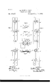
- Figure l is a front View of the steels with the fasteners engaged.
- Fig. 2 is acorresponding view with the fasteners disengaged.
- the remaining figures show details of one of the intermediate clasps on a larger scale.
- Fig. 3 is a face view of the spring-plate.
- Fig. 4 is a corresponding View of the main plate.
- Fig. 5 is a face View of the two plates properly superposed and riveted to the steel.
- Fig. 6 is a horizontal section showing the same with the opposite steel in position and with the post engaged.
- a and B are two steels, and A A are posts stiffly set in the steel A. These posts have each a sufficiently stout shank for strength and a larger head at the front or outer end.
- the fastener at the top is that described in my patent of 1890 referred to.
- the fastener at the lower end is composed of a single ordinary plate M, riveted to the part B and having a sufficiently-large hole to receive the head ofthe corresponding post A and a closed slot extending horizontally a little distance therefrom and then completely arrested.
- the post on being thrust through the large hole and allowed to move outward in this horizontal closed slot is held in the ordinary manner.
- the shank of the post fills the slot, so that there is no appreciable end play.
- the intermediate fastenings are peculiar. They are each composed of an inner or main plate D and an outer or spring-plate E.
- the inner plate D has a large hole d, which allows the head of the post to be entered in the same manner as the ordinary fastening.
- the first portion 61' is horizontal and allows the post to move outward in obedience to the ordinary distending strain of the corset.
- a second and important part (Z of the slot is inclined downward obliquely. The inclination may be varied. Forty-five degrees would serve well. I prefer an angle of about sixty degrees, as shown.
- the spring-plate E is formed as in my previous patent with a domed portion E immediately over the hole 01; but instead of having simply a hole at. 6 over the angle where the slot in the back plate D changes its direction from the horizontal portion (1, I have an inclined slot 6 in this spring-'plate-E, coinciding in inclination and in position with the inclined portion (1 of the slot below'oi' behind it.
- the extension of the spring-plate E outward beyond the main plate D,- which forms an important and necessary feature in my previous patent referred to is not required in the present fastener. I allow the spring plate to terminate with a smoothly-rounded end flush with the end of the main plate D.
- the wearer liberates the bottom fastening by the ordinary movement, drawing the steels together and moving the head A inward through the hole m. Then she detaches the upper fastening, that described in my patent of 1890, by a simple deflecting of the spring-plate outward by the fingers. Now the steels are free to move endwise relatively to each'otheigand they instantly do so, impelled by the inclinationof the grooves d 6 and the several posts escape automatically from the inclined slots and the corset is unfastened.
- a fastening provided with a horizontal guideway, the latter having also a spring-plate with a handle or wing to allow it to be conveniently lifted, so as to liberate its post by a horizontal movement of the latter, all substantially as herein specified.
Landscapes
- Health & Medical Sciences (AREA)
- General Health & Medical Sciences (AREA)
- Physical Education & Sports Medicine (AREA)
- Engineering & Computer Science (AREA)
- Textile Engineering (AREA)
- Joining Of Building Structures In Genera (AREA)
Description
(No Model.) DE WITT 0. COLE.
OORSET FASTENING. No. 466,902. Patented Jan. 12,1892.
mhw
Fries.
ATENT DE TVITT O. COLE, OF NEW YORK, N. Y.
CORSET-FASTENING.
SPECIFICATION forming part of Letters Patent No. $66,902, dated January 12, 1892. Application filed November 7, 1891. $erial No. 411,163. (No model.)
1'0 all whom it may concern.-
Be it known that I, DE WITT O. COLE, a citizen of the United States, residing in the city and county of New York, in the State of New York, have invented a certain new and useful Improvement in Oorset-Fastenings, of which the following is a specification.
My improvement relates to the construction of the fasteners and to the means for holding and releasing them. It allows the corset to be held securely and strongly at as many points as maybe required andto be fastened with ease, and especially to be liberated instantaneously when desired. It is common to have two steels extending up and down, one at each of the edges, which are to be joined and detached at will. A common form of fastener is to have a headed post standing rivetwise in one steel and engagingin a closed slot in a plate riveted to the other steel, the inner end of the closed slot being large enough to receive the head and the rest of the slot extending horizontally therefrom being only of a width sufficient to receive the shank.
I have in a patent to me dated October28, 1890, No. 438,385, described a fastener in which there are on one steel plates each having open horizontal slots with a large hole at the inner end of each, which large hole receives the head of the corresponding post carried on the other steel. This fastener allows the posts to each move a little distance in its proper slot, and then causes it to be arrested by being received in a hole in a spring-plate riveted on the outer face of the main plate. The spring-plate, until it is lifted by the finger, retains the post not only against the escape through the slot by the direct pull to which it is ordinarily subjected when the corset is in use, but also prevents the post being detached by being moved backward when in any emergency the corset is compressed or drawn together.
The present improved corset employs an ordinary fastener of the construction first briefly described at the bottom of the series, and one of my fasteners set forth in the said patent of 1890 at the top of the series. The intermediate fasteners, usually three, (but the number may be greater or less,) are of a peculiar construction. They have open slots opening outward, but the slots are inclined all in the same direction. I have in my experiments inclined them downward, and will describe the invention as thus carried out. The posts are retained in such inclined slots so long as the corset is in use, and are allowed to move downward and outward through them when the wearer desires to detach the fasteners. The posts, instead of moving out by a horizontal movement, move downward obliquely. This movement downward by one steel relatively to the other in the act of being disengaged renders it possible to hold the fasteners engaged, and to effect their liberation, when desired, by a different method from that involved in my previous patent.
The posts are received through a sufficient hole in the plate in the ordinary and longapproved manner. To retain them,it is only necessary to provide efficient means to resist any endwise movement of the steels relatively to each other. I employ two fasteners for this purpose, each adapted to resist the end movement, located one at the top and the other at the bottom of the steels. The uppermost is, as before stated, my fastener of 1890 and the lowermost an ordinary plain fastener. The intermediate fasteners have eachaspringplate; but these plates do not require to be lifted to liberate their several posts. The only function of the spring-plate in these intermediate fasteners is to prevent such fastener being detached by the backward movement of the post-in the slot. The large hole in the main plate receives the post, as in the previous patent referred to, and allows it to be moved laterally a little. The first or inner part of the slot in this the main plate is horizontal, as in the previous form,and allows the post to move horizontally outward to the place in which it is to be retained. The movement of the post in this part of the slot is the same as in the previous patent, and the springplate, in allowing this part of the movement of the post, rises a little to allow the head to so move, and snaps inward behind the head to prevent its return.
I have in my experiments inclined the several slots downward at an angle of about sixty degrees from the horizontal. The angle should not exceed the angle of friction. It is important that the post be not only free to move downward and escape Whenthe other fasteners which resist the end motion are detached and the steels are allowed to move endwise relatively to each other, but also that the angle shall be such that the ordinary distending force on the corset shall be sure to move the posts downward or upward, according to the inclination, and thus promptly liberate the fastenings without requiring any assistance beyond the simple distending strain.
One fastener to resist the end strain would be sufficient, but two are completely reliable. It is easy to obtain access to liberate the fasteners at the top and bottom, which prevent the end movement.
1 The accompanying drawings form apart of this specification and represent what I consider the best means of carrying out the invention.
Figure l is a front View of the steels with the fasteners engaged. Fig. 2 is acorresponding view with the fasteners disengaged. The remaining figures show details of one of the intermediate clasps on a larger scale. Fig. 3 is a face view of the spring-plate. Fig. 4 is a corresponding View of the main plate. Fig. 5 is a face View of the two plates properly superposed and riveted to the steel. Fig. 6 is a horizontal section showing the same with the opposite steel in position and with the post engaged.
Similar letters of reference indicate corresponding parts in all the figures where they appear.
As in my previous patent referred to, A and B are two steels, and A A are posts stiffly set in the steel A. These posts have each a sufficiently stout shank for strength and a larger head at the front or outer end. The fastener at the top is that described in my patent of 1890 referred to. The fastener at the lower end is composed of a single ordinary plate M, riveted to the part B and having a sufficiently-large hole to receive the head ofthe corresponding post A and a closed slot extending horizontally a little distance therefrom and then completely arrested. The post on being thrust through the large hole and allowed to move outward in this horizontal closed slot is held in the ordinary manner. The shank of the post fills the slot, so that there is no appreciable end play. The two steels are held by these fastenings, so that they can not be moved endwise rela tively to each other until these fasteners are both detached. The detaching of these,when required, is effected in the ordinary manner, the lowermost by forcing the steels together and removing the head by an inward movement through the hole in which it was entered, and then the upper fastener isliberated, as described in the patentot 1890, by simply lifting the spring-plate.
The intermediate fastenings are peculiar. They are each composed of an inner or main plate D and an outer or spring-plate E. The inner plate D has a large hole d, which allows the head of the post to be entered in the same manner as the ordinary fastening. There are two parts of the slot leading from the central hole outward. The first portion 61' is horizontal and allows the post to move outward in obedience to the ordinary distending strain of the corset. A second and important part (Z of the slot is inclined downward obliquely. The inclination may be varied. Forty-five degrees would serve well. I prefer an angle of about sixty degrees, as shown.
The spring-plate E is formed as in my previous patent with a domed portion E immediately over the hole 01; but instead of having simply a hole at. 6 over the angle where the slot in the back plate D changes its direction from the horizontal portion (1, I have an inclined slot 6 in this spring-'plate-E, coinciding in inclination and in position with the inclined portion (1 of the slot below'oi' behind it. The extension of the spring-plate E outward beyond the main plate D,- which forms an important and necessary feature in my previous patent referred to is not required in the present fastener. I allow the spring plate to terminate with a smoothly-rounded end flush with the end of the main plate D.
In putting on the corset the wearer engages, first, the fastening of 1890 at the top. This, in addition to holding the steels together, forbids the movement of the steels endwise rel atively to each other. Then the wearer successively engages the several middle fastenings, making the same movement to engage them as with the upper, simply thrusting the post forward through the hole (1, and allowing it to move by the ordinary distending strain through the horizontal portion d of the slot. Lastly, she engages the lower and ordinary fastening in the ordinary way. The corset is now reliably secured at each=of the several points.
To remove the corset the wearer liberates the bottom fastening by the ordinary movement, drawing the steels together and moving the head A inward through the hole m. Then she detaches the upper fastening, that described in my patent of 1890, by a simple deflecting of the spring-plate outward by the fingers. Now the steels are free to move endwise relatively to each'otheigand they instantly do so, impelled by the inclinationof the grooves d 6 and the several posts escape automatically from the inclined slots and the corset is unfastened.
Modifications may be made without departing from the principle or sacrificing the advantages of the invention. There may be only my fastening of 1890, shownat thetop, or only the ordinary fastening, shown at the bottom, to resist the end movement of the steels. The position of these parts may be reversed, the ordinary fastening at the top and my fastening of 1890 at the bottom. I can use my fastening of 1890 at both the top and bottom or the ordinary fastening at both these points, and I can work with some success by using other means than either such fastening, so long as it is capable of cffectually resisting the end movement of the steels relatively to each other and capable of being readily disengaged or unlocked when required. There may be a greater or less number of my peculiar fastenings with their inclined slots. I prefer to have my fastener of 1890 at the top and an ordinary fastener at the bottom, and all the intermediate fastenings of the new construction described.
I claim as my invention- 7 1. The steel B, plates D, having similar inclined slots (Z and the steel A and posts A set therein, in combination with each other and with the spring-plate E for each plate D, provided with a corresponding inclined way e adapted to prevent a backward movement of the post, and with means for resisting or allowing the end motion of the steels relatively to each other at will, as herein specified.
2. The steel B, plates D, having similar inclined slots d and the steel A and posts A set therein, in combination with each other and with the spring-plate E for each plate D,
provided with a corresponding inclined way c and adapted to preventabackward movement of the post, a fastening provided with a horizontal guideway, the latter having also a spring-plate with a handle or wing to allow it to be conveniently lifted, so as to liberate its post by a horizontal movement of the latter, all substantially as herein specified.
3. The steel B, plates D, having similar inclined slots d and the steel A and post A set therein, in combination with the springplate E for each plate D, provided with a corresponding inclined way adapted to prevent a backward movement of the post, and with two additional fasteningsarranged at the top and bottom, respectively, each adapted to re sist an end movement of the steels relatively to each other, and to be easily liberated when required, as herein specified.
In testimony that I claim the invention above set forth I aflix my signature in presence of two witnesses.
DE WITT O. COLE. WVitnesses:
CHARLES R. SEARLE, M. F. BOYLE.
Publications (1)
| Publication Number | Publication Date |
|---|---|
| US466902A true US466902A (en) | 1892-01-12 |
Family
ID=2535766
Family Applications (1)
| Application Number | Title | Priority Date | Filing Date |
|---|---|---|---|
| US466902D Expired - Lifetime US466902A (en) | De witt c |
Country Status (1)
| Country | Link |
|---|---|
| US (1) | US466902A (en) |
-
0
- US US466902D patent/US466902A/en not_active Expired - Lifetime
Similar Documents
| Publication | Publication Date | Title |
|---|---|---|
| US466902A (en) | De witt c | |
| US377648A (en) | Bmile sinning | |
| US1368048A (en) | Lock | |
| US5596A (en) | Alonzo d | |
| US756924A (en) | Bag-fastener. | |
| US1145478A (en) | Lock for straps of mail-bags. | |
| US378016A (en) | Fastening for traveling-bags or valises | |
| US553399A (en) | Karl count esteriiazy | |
| US174740A (en) | Improvement in pocket-book fastenings | |
| US325192A (en) | Whiffletree-hook | |
| US237803A (en) | Corset-steel fastening | |
| US526491A (en) | Albert w | |
| US58916A (en) | Improved door-guard | |
| US300192A (en) | Weisel bbale | |
| US42052A (en) | Joseph h | |
| US573093A (en) | Lock-buckle | |
| US614336A (en) | Sash-fastener | |
| US249618A (en) | hayem | |
| US598743A (en) | Michael perez | |
| US553499A (en) | Fastener for window-shutters | |
| US66638A (en) | busseii | |
| US312238A (en) | Corset-fastening | |
| US1149022A (en) | Keyless padlock. | |
| US620049A (en) | Fastener for stock-cars | |
| US317736A (en) | John jay co well |