US465904A - Dumping-wagon - Google Patents
Dumping-wagon Download PDFInfo
- Publication number
- US465904A US465904A US465904DA US465904A US 465904 A US465904 A US 465904A US 465904D A US465904D A US 465904DA US 465904 A US465904 A US 465904A
- Authority
- US
- United States
- Prior art keywords
- wagon
- bed
- dumping
- frame
- turn
- Prior art date
- Legal status (The legal status is an assumption and is not a legal conclusion. Google has not performed a legal analysis and makes no representation as to the accuracy of the status listed.)
- Expired - Lifetime
Links
- 230000003028 elevating effect Effects 0.000 description 3
- 239000003245 coal Substances 0.000 description 2
- 238000010276 construction Methods 0.000 description 1
- 230000000284 resting effect Effects 0.000 description 1
Images

Classifications
-
- B—PERFORMING OPERATIONS; TRANSPORTING
- B60—VEHICLES IN GENERAL
- B60P—VEHICLES ADAPTED FOR LOAD TRANSPORTATION OR TO TRANSPORT, TO CARRY, OR TO COMPRISE SPECIAL LOADS OR OBJECTS
- B60P1/00—Vehicles predominantly for transporting loads and modified to facilitate loading, consolidating the load, or unloading
- B60P1/04—Vehicles predominantly for transporting loads and modified to facilitate loading, consolidating the load, or unloading with a tipping movement of load-transporting element
- B60P1/06—Vehicles predominantly for transporting loads and modified to facilitate loading, consolidating the load, or unloading with a tipping movement of load-transporting element actuated by mechanical gearing only
- B60P1/14—Vehicles predominantly for transporting loads and modified to facilitate loading, consolidating the load, or unloading with a tipping movement of load-transporting element actuated by mechanical gearing only with cables, chains, or the like
Definitions
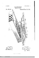
- Figure 1 of the drawings is a perspective view.
- Fig. 2 is a bottom plan view of wagonbed, and
- Fig. 3 is a detail view.
- This invention relates to certain improvements in dumping-wagons, especially for coal; and it consists in the novel construction and combination of parts, as will appear from the following description and accompanying drawings.
- A refers to the bed-frame, and B to the body, of a dumping-wagon.
- O is a turn-table, which is centrally pivoted upon a cross-bar of the bed-frame A and rotatable upon friction rolls or bearings b, hung in other crossbats of said bed-frame.
- D D are hinge-rods pivotally connected at their lower ends to pivot-rods 0, held centrally in cross-pieces or cleatsof the turn-table O and pivoted at their upper ends to plates secured to the bottom of the wagon-body B, near its rear end.
- E E are parallel longitudinal screws having their bearings in the end pieces of the bedframe A and provided with angular ends to permit of the application thereto of a crank or winch for their manipulation.
- Each of these screws has upon opposite sides of its center a right and left handed screw-thread f f, with which engage nuts or blocks g, forming fulcrums for the distant or outer ends of jointed or sectional rods or props F E, which at their maximum depression are out of contact with the wagon-body.
- Bearing-plates h h for the jointed or sectional rods or props F F are provided upon the bottom of the wagonbody.
- V 1 In a dumping-Wagon, the combination, with the turn-table held upon the bed-frame, of the hinge-rods connected to said turn-table and to the wagon-body, and means for elevating said wagon-body, substantiallyas set forth.
- I11 a coal or dumping wagon, the combination, with the bed-frame and body having a hinge or pivotal connection with said frame, of the angular levers having each a series of stepped shoulders or teeth adapted to engage the bed-frame, substantially as set forth.
Landscapes
- Engineering & Computer Science (AREA)
- Transportation (AREA)
- Mechanical Engineering (AREA)
- Tables And Desks Characterized By Structural Shape (AREA)
Description
(No Model.) 2 Sheets-Sheet 2.
H. P. WAYMAN.
DUMPING WAGON.
No. 465,904. Patented Dec. 29, 1891.
fl p/3,
WfI/VESSE'S 1. V) EN? 0% NrTED STATES HENRY P. \VAYMAN, OF TRENTON, NEXV JERSEY.
DUMPlNGfWAGON.
SPECIFICATION forming part of Letters Patent No. 465,904, dated December 29,1891. Application filed March '7, 1890. fier ial No. 342,996. (No model.)
To all whom it may concern:
Be it known that I, HENRY P. WAYMAN, a citizen of the United States, and a resident of Trenton, in the county of Mercer and State of New Jersey, have invented certain new and useful Improvements in Dumping-Wagonsg and I do declare the following to be a full, clear, and exact description of the invention, such as will enable others skilled in the art to which it appertains to make and use the same, reference being had to the accompanying drawings, and to letters of reference marked thereon, which form a part of this specification.
Figure 1 of the drawings is a perspective view. Fig. 2 is a bottom plan view of wagonbed, and Fig. 3 is a detail view.
This invention relates to certain improvements in dumping-wagons, especially for coal; and it consists in the novel construction and combination of parts, as will appear from the following description and accompanying drawings.
In the drawings,A refers to the bed-frame, and B to the body, of a dumping-wagon.
O is a turn-table, which is centrally pivoted upon a cross-bar of the bed-frame A and rotatable upon friction rolls or bearings b, hung in other crossbats of said bed-frame.
D D are hinge-rods pivotally connected at their lower ends to pivot-rods 0, held centrally in cross-pieces or cleatsof the turn-table O and pivoted at their upper ends to plates secured to the bottom of the wagon-body B, near its rear end. I
Upon the bed-frame A, at its ends, are secured curved plates or tracks cl, upon which rest and travel frictional rolls or wheels 6, hung upon the under side of the body B, at its corners, as the body is revolved with the turn-table.
E E are parallel longitudinal screws having their bearings in the end pieces of the bedframe A and provided with angular ends to permit of the application thereto of a crank or winch for their manipulation. Each of these screws has upon opposite sides of its center a right and left handed screw-thread f f, with which engage nuts or blocks g, forming fulcrums for the distant or outer ends of jointed or sectional rods or props F E, which at their maximum depression are out of contact with the wagon-body. Bearing-plates h h for the jointed or sectional rods or props F F are provided upon the bottom of the wagonbody.
At the sides of the wagon-body are hung, as in my concurrent application,stepped handlevers G for engagement with studs or projections 7t on the sides of the bed-frame, for the temporary support of the wagon-body at the lower end when elevated as shown.
It will be seen that after the wagon-body has been swung around with the turn-table by the attendant or driver transversely to the length of the bed-frame, and then by applying a winch or crank to one of said screws say that one next to the rear end of the wagonbody'the jointed or sectional rods or props thereof will be flexed or bowed upward against its respective bearing-plate on said wagonbody, thus raising or elevating the corresponding or rear end of said body, the hinge-rods permitting this. The levers G are at the same time brought into use to temporarily thus holdsaid end of the wagon-body. Now by similarly manipulating the other screw the front end of the wagon-body is elevated as desired. (Indicated in Fig. 1.) From this arrangement will be observed that the bearing of the wagonbody as it is elevated is wholly removed from the bed-frame by reason of employment of the hinge-rods, the latter being adapted or permitted to rise with said body as it is elevated.
Having thus described my invention, what I claim as new, and desire to secure by Letters Patent, is V 1. In a dumping-Wagon, the combination, with the turn-table held upon the bed-frame, of the hinge-rods connected to said turn-table and to the wagon-body, and means for elevating said wagon-body, substantiallyas set forth.
2. In a dumping-Wagon, the combination, with the wagon-body and means for hinging or pivotally supporting it in an elevated position, of the longitudinal screws having right and left hand screw-threads and supported in the bed-frame, and the sectional or jointed props or rods engaging said screws and acting upon said wagon-body, substantially as speci fied.
3. In a dumping-wagon, the combination, with the bed-frame carrying the turn-table, the wagon-body having hinge or pivotingrod connection with said turn table, and
substantially as specified.
5. I11 a coal or dumping wagon, the combination, with the bed-frame and body having a hinge or pivotal connection with said frame, of the angular levers having each a series of stepped shoulders or teeth adapted to engage the bed-frame, substantially as set forth.
6. In a dumping-wagon, the combination, with the bed-plate, a turn -table mounted thereon, a wagon-b0dy resting normally on the turn-table, and links connecting the body to the turn-table, of elevating devices between the body and the bed plate, substantially as described.
7. In a dumping-wagon, the combination of the bed plate having a turn table mounted thereon, a wagon-bod y connected to said turntable by links, toggle-levers between the body and bed-plate, and screw-threaded shafts for operating the same, substantially as specified.
In testimony whereof I aiiixniy signature in presence of two witnesses.
HENRY P. \VAYMAN.
\Vitnesses:
PHILIP C. MAsI, CHAS. L. TAYLOR.
Publications (1)
| Publication Number | Publication Date |
|---|---|
| US465904A true US465904A (en) | 1891-12-29 |
Family
ID=2534768
Family Applications (1)
| Application Number | Title | Priority Date | Filing Date |
|---|---|---|---|
| US465904D Expired - Lifetime US465904A (en) | Dumping-wagon |
Country Status (1)
| Country | Link |
|---|---|
| US (1) | US465904A (en) |
Cited By (1)
| Publication number | Priority date | Publication date | Assignee | Title |
|---|---|---|---|---|
| US2852304A (en) * | 1954-03-15 | 1958-09-16 | Lew E Harrison | Dumping wheelbarrow |
-
0
- US US465904D patent/US465904A/en not_active Expired - Lifetime
Cited By (1)
| Publication number | Priority date | Publication date | Assignee | Title |
|---|---|---|---|---|
| US2852304A (en) * | 1954-03-15 | 1958-09-16 | Lew E Harrison | Dumping wheelbarrow |
Similar Documents
| Publication | Publication Date | Title |
|---|---|---|
| US1105631A (en) | Timber-dolly. | |
| US1100702A (en) | Truck. | |
| US1394113A (en) | Dumping-wagon | |
| US640942A (en) | Elevator-truck. | |
| US700086A (en) | Dumping-wagon. | |
| US573987A (en) | Fifths to j | |
| US431064A (en) | Dumping-wagon | |
| US1259227A (en) | Chute. | |
| US798566A (en) | Dumping-wagon. | |
| US943013A (en) | Moving implement. | |
| US140703A (en) | Improvement in dumping-wagons | |
| US1114282A (en) | Elevating-truck. | |
| US434375A (en) | Device for unloading cars | |
| US356473A (en) | Hand-truck | |
| US1347375A (en) | Dumping-bed for wagons | |
| US593306A (en) | muller | |
| US367412A (en) | knowlton | |
| US614796A (en) | Truck | |
| US719533A (en) | Dumping-wagon. | |
| US333844A (en) | Dumping-wagon | |
| US968564A (en) | Piano-truck. | |
| US681927A (en) | Dumping-wagon. | |
| US691542A (en) | Baggage-truck. | |
| US547067A (en) | Hay-rack | |
| US301316A (en) | Dumping-wagon |