US4659016A - Hot-melt dispenser with aimable nozzles - Google Patents
Hot-melt dispenser with aimable nozzles Download PDFInfo
- Publication number
- US4659016A US4659016A US06/664,618 US66461884A US4659016A US 4659016 A US4659016 A US 4659016A US 66461884 A US66461884 A US 66461884A US 4659016 A US4659016 A US 4659016A
- Authority
- US
- United States
- Prior art keywords
- nozzle
- nozzles
- hot
- manifold
- orifice
- Prior art date
- Legal status (The legal status is an assumption and is not a legal conclusion. Google has not performed a legal analysis and makes no representation as to the accuracy of the status listed.)
- Expired - Lifetime
Links
- 239000012943 hotmelt Substances 0.000 title claims abstract description 22
- 238000007789 sealing Methods 0.000 claims abstract description 7
- 239000000853 adhesive Substances 0.000 claims description 40
- 230000001070 adhesive effect Effects 0.000 claims description 40
- 239000004831 Hot glue Substances 0.000 claims description 18
- 239000000463 material Substances 0.000 claims description 14
- 239000002184 metal Substances 0.000 claims description 13
- 229910052751 metal Inorganic materials 0.000 claims description 13
- 238000004140 cleaning Methods 0.000 description 4
- 206010013642 Drooling Diseases 0.000 description 3
- 208000008630 Sialorrhea Diseases 0.000 description 3
- 229910000831 Steel Inorganic materials 0.000 description 3
- 230000000712 assembly Effects 0.000 description 3
- 238000000429 assembly Methods 0.000 description 3
- 238000001816 cooling Methods 0.000 description 3
- 238000004806 packaging method and process Methods 0.000 description 3
- 239000010959 steel Substances 0.000 description 3
- 229910001369 Brass Inorganic materials 0.000 description 2
- 239000010951 brass Substances 0.000 description 2
- 230000008878 coupling Effects 0.000 description 2
- 238000010168 coupling process Methods 0.000 description 2
- 238000005859 coupling reaction Methods 0.000 description 2
- 238000010438 heat treatment Methods 0.000 description 2
- 239000002245 particle Substances 0.000 description 2
- 239000004822 Hot adhesive Substances 0.000 description 1
- 230000004913 activation Effects 0.000 description 1
- 238000007792 addition Methods 0.000 description 1
- 229910052782 aluminium Inorganic materials 0.000 description 1
- XAGFODPZIPBFFR-UHFFFAOYSA-N aluminium Chemical compound [Al] XAGFODPZIPBFFR-UHFFFAOYSA-N 0.000 description 1
- 238000010276 construction Methods 0.000 description 1
- 238000011109 contamination Methods 0.000 description 1
- 230000003247 decreasing effect Effects 0.000 description 1
- 238000002844 melting Methods 0.000 description 1
- 230000008018 melting Effects 0.000 description 1
- 238000005086 pumping Methods 0.000 description 1
- 230000005855 radiation Effects 0.000 description 1
- 238000009877 rendering Methods 0.000 description 1
- 230000000717 retained effect Effects 0.000 description 1
- 239000007921 spray Substances 0.000 description 1
Images


Classifications
-
- B—PERFORMING OPERATIONS; TRANSPORTING
- B65—CONVEYING; PACKING; STORING; HANDLING THIN OR FILAMENTARY MATERIAL
- B65B—MACHINES, APPARATUS OR DEVICES FOR, OR METHODS OF, PACKAGING ARTICLES OR MATERIALS; UNPACKING
- B65B51/00—Devices for, or methods of, sealing or securing package folds or closures; Devices for gathering or twisting wrappers, or necks of bags
- B65B51/02—Applying adhesives or sealing liquids
- B65B51/023—Applying adhesives or sealing liquids using applicator nozzles
-
- B—PERFORMING OPERATIONS; TRANSPORTING
- B05—SPRAYING OR ATOMISING IN GENERAL; APPLYING FLUENT MATERIALS TO SURFACES, IN GENERAL
- B05C—APPARATUS FOR APPLYING FLUENT MATERIALS TO SURFACES, IN GENERAL
- B05C5/00—Apparatus in which liquid or other fluent material is projected, poured or allowed to flow on to the surface of the work
- B05C5/001—Apparatus in which liquid or other fluent material is projected, poured or allowed to flow on to the surface of the work incorporating means for heating or cooling the liquid or other fluent material
-
- B—PERFORMING OPERATIONS; TRANSPORTING
- B05—SPRAYING OR ATOMISING IN GENERAL; APPLYING FLUENT MATERIALS TO SURFACES, IN GENERAL
- B05C—APPARATUS FOR APPLYING FLUENT MATERIALS TO SURFACES, IN GENERAL
- B05C5/00—Apparatus in which liquid or other fluent material is projected, poured or allowed to flow on to the surface of the work
- B05C5/02—Apparatus in which liquid or other fluent material is projected, poured or allowed to flow on to the surface of the work the liquid or other fluent material being discharged through an outlet orifice by pressure, e.g. from an outlet device in contact or almost in contact, with the work
- B05C5/0208—Apparatus in which liquid or other fluent material is projected, poured or allowed to flow on to the surface of the work the liquid or other fluent material being discharged through an outlet orifice by pressure, e.g. from an outlet device in contact or almost in contact, with the work for applying liquid or other fluent material to separate articles
- B05C5/0212—Apparatus in which liquid or other fluent material is projected, poured or allowed to flow on to the surface of the work the liquid or other fluent material being discharged through an outlet orifice by pressure, e.g. from an outlet device in contact or almost in contact, with the work for applying liquid or other fluent material to separate articles only at particular parts of the articles
- B05C5/0216—Apparatus in which liquid or other fluent material is projected, poured or allowed to flow on to the surface of the work the liquid or other fluent material being discharged through an outlet orifice by pressure, e.g. from an outlet device in contact or almost in contact, with the work for applying liquid or other fluent material to separate articles only at particular parts of the articles by relative movement of article and outlet according to a predetermined path
Definitions
- the invention relates to a nozzle assembly for a hot-melt adhesive dispenser and more particularly to a multi-orifice nozzle assembly having aimable nozzles for the low pressure dispensing of hot-melt adhesive.
- Hot-melt adhesives are used extensively for case and carton sealing on automated packaging machinery. Inherent in hot-melt adhesive dispensers are the problems of soiling, drooling and stringing between applications.
- the typical solutions to these problems are the employment of (1) nozzle assemblies containing pressure activated valves such as that seen in U.S. Pat. No. 3,608,793 and/or (2) small diameter nozzle orifices. Both of these solutions require the use of high pressure equipment, either to insure activation of the valve or to supply a sufficient amount of adhesive to the carton flaps through the small diameter orifices.
- High pressure equipment is more expensive than that used in low pressure applications and at the same time it is potentially dangerous since a rupture in the equipment could spray melted adhesive in any direction.
- U.S. Pat. No. 3,981,123 shows a hot-melt adhesive apparatus which applies adhesive to the top and bottom flaps of a carton. A large portion of the elements that make up the apparatus are present only for the purpose of aligning the box for proper adhesive application. The apparatus must be realigned each time a different sized box enters the assembly line.
- An object of the present invention was to provide a reliable, uncomplicated hot-melt adhesive dispenser for application on an automated assembly line.
- a further object was to devise a multi-orifice nozzle assembly that could be used with low-pressure hot-melt adhesive dispensers and that would maintain clean nozzle cutoff between applications without drips, drools, or leaks from the nozzle tip.
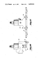
- FIG. 1 is a perspective view showing the apparatus of the present invention in a carton sealing configuration for the application of hot-melt adhesive to carton flaps.
- FIG. 2 is a front view of the apparatus of FIG. 1.
- FIG. 3 is a plan view of the upper nozzle manifold assembly and head of FIG. 2.
- FIG. 5 is a partially cutaway front view of a dispensing bar with nozzle tips and wear bars.
- FIG. 6 is a partially cutaway perspective view of the dispensing bar of FIG. 5.
- FIG. 7 is a sectional side view of a nozzle tip inserted into a dispensing bar, taken along 7--7 of FIG. 5.
- FIG. 8 is a plan view of the lower nozzle manifold assembly and head of FIG. 2.
- FIG. 9 is a side view of the manifold of FIG. 8.
- FIG. 10 is a front view of a heated dispenser head with associated coupling
- FIG. 11 is a side view of the apparatus of FIG. 10.
- FIG. 12 is a front view of an upper nozzle manifold assmbly having two nozzle tips
- FIG. 13 is a side view of the apparatus of FIG. 12.
- FIG. 14 is a side view of a lower nozzle manifold assembly having eight nozzle tips.
- FIG. 15 is a front view of the apparatus of FIG. 14.
- FIG. 16 is a side view of an upper nozzle manifold assembly having eight nozzle tips.
- FIG. 17 is a front view of the apparatus of FIG. 16.
- the present invention for the dispensing of hot-melt adhesive material is a nozzle manifold assembly having nozzles of larger orifice diameter located on a dispensing bar with both material and heat conducting paths to a heated low pressure hot-melt dispenser head.
- the nozzle assembly is designed to ensure that sufficient flow of the adhesive is maintained under low pressure delivery conditions of below 150 pounds per square inch, while preventing the tendency of melted adhesive to drool from the larger diameter orifice in the nozzle tips.
- FIG. 1 two embodiments of the nozzle manifold assembly 11a and 11b of the present invention are shown in use in an automatic packaging assembly line.
- a carton 13 moves along rollers (not shown) in the direction of the arrow A, hot-melt adhesive is dispensed from the nozzles 14 to the outside surfaces 15 of the top minor flaps of the box and to the inside surfaces 16 of the bottom major flaps.
- the top-apply manifold assembly 11a is shown as an inverted T-shape configuration with nozzles 14 placed on the front side of the dispensing head.
- the bottom-apply manifold assembly 11b is of a Y-shape configuration with the nozzles 14 facing toward the dispenser head 17, thus facilitating contact with the inner surface 16 of the bottom major flaps of the box.
- FIG. 2 shows that direct contact of the box surface with the aimable, adhesive dispensing nozzles 14 is prevented by interspersing semicircular wear bars 20 which ride along the box surface.
- FIGS. 3 and 4 show details of the connections between the dispenser head 17 and the nozzle manifold assembly 11a.
- An important element of the nozzle manifold assembly is shown in FIGS. 3 and 4.
- a high thermal conductivity, metal, heat transfer block 19, made of a material such as aluminum, is placed in heat conducting relationship between the heated dispenser head 17 and a brass nozzle manifold inlet section 21, shown in FIG. 4.
- the heat transfer block 19 provides a heat flow path that is separate from the adhesive flow path, thereby avoiding the extra expense and complexity that would result from adding a second heating unit to the nozzle manifold assembly. Any variation in tolerances of sizes of the interconnected heat transfer block and inset section is adjusted by the swivel nut 22. Screws 23 are used to connect the heat transfer block 19 to both the head and the inlet.
- FIG. 4 also shows the adhesive flow path of the nozzle manifold assembly 11a.
- the inlet section of the manifold 21, having a 0.089 inch diameter hollow center bore, not shown, is joined to the dispenser head 17 by means of the swivel nut 22 in a direct hot-melt material dispensing line with the inlet hose 18.
- the swivel nut 22 allows tolerances for a leak-free attachment of the inlet section of the manifold to both the dispenser head 17 and to the heat transfer block 19.
- the inlet section 21 is connected to the mid-section of a rectangularly shaped dispensing bar 24, shown in FIG. 5.
- the dispensing bar has an 0.089 inch bore 25, which lines up with the center bore of the inlet section and a longitudinal 0.089 inch bore 26, which opens to the outside through multiple holes into which nozzle heads 14 are inserted.
- screws 27 are placed at both ends of the longitudinal or lengthwise inner bore 26, to facilitate cleaning of the nozzle manifold interior.
- Interspersed between the nozzles on the dispensing bar are semicircular wear bars 20.
- the holes 28 that open the 0.089 inch diameter bore to the outside can be seen.
- the rectangular cross-sectional shape of the dispensing bar 24 provides maximum strength while rendering a minimization of thermal radiation surface between the surrounding air and the hot-melt-adhesive-containing bores.
- the diameter of the passageway through this dispensing bar is preferably 0.089 inch. Smaller diameters would not permit an adequate adhesive flow under low pressure delivery conditions. A larger diameter would result in poor cutoff of adhesive flow and increase the tendency of the nozzle to drool. A viable range of diameters is 0.079 to 0.120 inches.
- FIG. 7 shows a sectional side view of the dispensing bar 24 and a nozzle taken along lines 7--7 of FIG. 5.
- a bolt 31 holds the nozzle head assembly in place.
- a primary orifice 33 joins the passageway 26 through the dispensing bar to a secondary orifice 35.
- the secondary orifice 35 lines up with the nozzle head orifice 37.
- the diameters of the nozzle assembly orifice 33, 35 and 37 are less than the diameter of the bore 26 through the dispensing bar 24 but they are, nevertheless, relatively large. Large diameter orifices are employed to significantly reduce nozzle plugging due to adhesive contamination. Small diameter orifices tend to plug frequently if in-line filters are not employed.
- a preferred range of nozzle orifice openings is between 0.010 and 0.090 inches in diameter.
- the nozzle assembly bolt 31 contains a plurality of secondary orifices 35, permitting the nozzle to be aimed in a variety of positions ranging from 0° to 180°, but at least between 60° to 120°, 0° and 180° being taken as a line parallel to the lengthwise dimension of the dispensing bar.
- This option allows a user to change the location of the tracks of adhesive which are dispensed along the flaps of the carton. Without aimable nozzles, the only way the track locations could be changed would be the replacement of the dispensing bar 24.
- the construction of the nozzle head assembly 14 also permits a user to disassemble the nozzles for cleaning or replacement purposes.
- the nozzle head assembly 14 should be made of steel for long wearing durability.
- the swivel nut conneection piece 22, inlet section 21 and dispensing bar 14 may be fashioned from brass.
- the wear bars 20 are made of steel and are positioned to prevent contact of the nozzle with the application surface.
- FIGS. 8 and 9 Another nozzle manifold assembly, for use in applying adhesive to the inner edges of the major flaps at the bottom of a container, is shown in FIGS. 8 and 9.
- the dispenser bar of this Y-shaped applicator assembly is split into two sections and joined to an inlet section 39, which has a hollow 0.089 inch diameter center bore in material transfer relationship with the dispenser head 17.
- the center bore diverges into two bores separated by angles of usually 110° or 130°.
- Each of the two sections of the dispensing bar 41 and 42 are joined at one of the two outlets of the diverging bores of inlet section 39.
- Center bores of 0.089 inch in each bar section continue the passageway for the melted adhesive to flow out of nozzles 14 placed on the side of the dispenser bars facing toward the dispenser head 17.
- melted adhesive may be applied to the inside edges of the partially opened bottom major flaps of the container.
- This embodiment has similar nozzle inserts and wear bars as previously described for the top-apply nozzle manifold assembly.
- a heat transfer block, 19, as previously described, is employed to provide a heat flow path that is separate from the adhesive flow path.
- FIGS. 10 and 11 show the heated dispenser head 17 and its related coupling.
- the hot-melt adhesive enters at inlet 43. After passing through the heated dispenser head 17 the adhesive exits through outlet 45.
- Dispenser heads are well known and are commercially available.
- the heads contain at least one valve and a heater unit.
- the apparatus as shown in FIGS. 10 and 11 remains the same for all embodiments of the nozzle manifold assembly.
- FIGS. 12 and 13 a second embodiment of the top-apply nozzle manifold assembly is shown.
- a swivel nut 22 and a dispensing bar 47 having only two, closely spaced, aimable nozzles 14 and one wear bar 20, is added to the apparatus of FIG. 11.
- the nozzles 14 should be no further than one inch from each other. If a dispensing bar contains only two nozzles but the nozzles are positioned at a distance greater than one inch from each, the preferred configuration is to add a heat transfer block and an inlet section to the nozzle manifold assembly of FIG. 12. The additions are preferred because the likelihood of adhesive cooling increases as the distance the adhesive must travel to the nozzle increases.
- a key design consideration for nozzle manifold assemblies having expanded dispensing bars 49 and 50 is to maintain the proper temperature at the most external nozzles 14.
- a cool dispensing bar or nozzle tip results in poor adhesive cutoff and stringing hot melt.
- a heat transfer block 51 transfers enough heat to the external nozzles 14, experiencing only a 40 or 50 degree temperature drop, and at the same time is in keeping with a second design consideration--avoidance of complicating the assembly with a second heating device.
- a swivel nut 22 is provided, as seen in FIG. 14. The adhesive path continues through the swivel connection to a turn block 53.
- the turn block 53 contains a 0.089 inch passageway, not shown, which delivers the adhesive to an inlet section 55. From the inlet section 55 the adhesive drops down into a longitudinal bore, not shown, that travels through the heat transfer block 51 from the dispensing bar 49 to the dispensing bar 50.
- the bore through the heat transfer block 51 is located just below the inlet section 55 as viewed in FIG. 15 and provides adhesive to the dispensing bars 49 and 50 close to the lowermost nozzles of the two bars.
- the heat flow path travels from the dispenser head 17, through the heat transfer block 51, to the dispensing bars 49 and 50.
- bolts 56 may be removed, thereby freeing the bars 49 and 50 from the rest of the assembly.
- the adhesive flow path of such an assembly is a simplified version of the flow path in FIG. 14.
- the adhesive comes from the dispenser head 17 and the swivel nut connection 22, through a turn block 57 and an inlet section 59, to the extended dispensing bar 61.
- the greater the length of a dispensing bar the greater the concern of adhesive cooling as it works its way through a low pressure applicator.
- a heat transfer block 63 having flared ends is employed. The flared ends of the block 63 increase the area of surface contact between the block and the dispensing bar 61. It is preferred that bolts 56 be utilized to permit a user to remove the extended dispensing bar 61 for cleaning or replacement.
- Each nozzle manifold assembly cited above may be used independently or the top-apply and bottom-apply eembodiments may be combined as in FIG. 1 in an automated assembly line for sealing boxes.
- the bottom outside flaps are folded partially and the top inside minor flaps are folded in.
- Hot-melt adhesive is dispensed from the nozzle tips, falling on the flaps in parallel strips. It is possible to control the length of the strips by a valving mechanism in the dispensing head so as to deposit short or long strips or dots of adhesive. It is possible to control the position of the strips by the choice of dispensing bars and by aiming the nozzles of the dispensing bar.
- the present invention permits dispensing of hot-melt adhesive at low pressures--150 psi and lower.
Landscapes
- Engineering & Computer Science (AREA)
- Mechanical Engineering (AREA)
- Coating Apparatus (AREA)
- Package Closures (AREA)
Abstract
Description
Claims (15)
Priority Applications (1)
| Application Number | Priority Date | Filing Date | Title |
|---|---|---|---|
| US06/664,618 US4659016A (en) | 1983-05-11 | 1984-10-25 | Hot-melt dispenser with aimable nozzles |
Applications Claiming Priority (2)
| Application Number | Priority Date | Filing Date | Title |
|---|---|---|---|
| US49371083A | 1983-05-11 | 1983-05-11 | |
| US06/664,618 US4659016A (en) | 1983-05-11 | 1984-10-25 | Hot-melt dispenser with aimable nozzles |
Related Parent Applications (1)
| Application Number | Title | Priority Date | Filing Date |
|---|---|---|---|
| US49371083A Continuation-In-Part | 1983-05-11 | 1983-05-11 |
Publications (1)
| Publication Number | Publication Date |
|---|---|
| US4659016A true US4659016A (en) | 1987-04-21 |
Family
ID=27051155
Family Applications (1)
| Application Number | Title | Priority Date | Filing Date |
|---|---|---|---|
| US06/664,618 Expired - Lifetime US4659016A (en) | 1983-05-11 | 1984-10-25 | Hot-melt dispenser with aimable nozzles |
Country Status (1)
| Country | Link |
|---|---|
| US (1) | US4659016A (en) |
Cited By (12)
| Publication number | Priority date | Publication date | Assignee | Title |
|---|---|---|---|---|
| US4951917A (en) * | 1989-12-06 | 1990-08-28 | Slautterback Corporation | Dynamic response time for electromagnetic valving |
| US4969601A (en) * | 1989-05-01 | 1990-11-13 | Slautterback Corporation | Directly thermally coupled adhesive dispenser |
| US5027976A (en) * | 1989-10-10 | 1991-07-02 | Nordson Corporation | Multi-orifice T-bar nozzle |
| US5217169A (en) * | 1991-07-08 | 1993-06-08 | Slautterback Corporation | Drool-retarding valving of a multi nozzle adhesive manifold |
| US5407101A (en) * | 1994-04-29 | 1995-04-18 | Nordson Corporation | Thermal barrier for hot glue adhesive dispenser |
| US5915591A (en) * | 1997-09-10 | 1999-06-29 | Illinois Tool Works Inc. | Electric solenoid valve for hot melt adhesive and method therefor |
| US20050284338A1 (en) * | 2004-06-01 | 2005-12-29 | Dwyer Patrick A | Hot melt adhesive |
| US20080083843A1 (en) * | 2002-02-21 | 2008-04-10 | Aisin Kako Kabushiki Kaisha | Wide split nozzle and coating method by wide slit nozzle |
| US20130140352A1 (en) * | 2011-12-05 | 2013-06-06 | Indag Gesellschaft Fur Industriebedarf Mbh & Co. Betriebs Kg | Packing carton and related machine and method |
| US20170368719A1 (en) * | 2016-06-24 | 2017-12-28 | Charles Allan Jones | Manifold assembly for resin infusion and injection |
| USD824968S1 (en) * | 2016-10-30 | 2018-08-07 | Nordson Corporation | Hot melt dispenser |
| US20190240943A1 (en) * | 2016-10-25 | 2019-08-08 | Sealed Air Corporation (Us) | Packaging assembly system |
Citations (28)
| Publication number | Priority date | Publication date | Assignee | Title |
|---|---|---|---|---|
| US535669A (en) * | 1895-03-12 | Lawn sprinkler | ||
| US919737A (en) * | 1908-08-10 | 1909-04-27 | Lester G Loomis | Lawn-sprinkler. |
| US1181145A (en) * | 1914-10-28 | 1916-05-02 | Oscar F Larson | Sprinkler-head. |
| GB205207A (en) * | 1922-07-14 | 1923-10-15 | Murphy James | Improvements in or relating to nozzles |
| US2299259A (en) * | 1940-09-09 | 1942-10-20 | Miehle Printing Press & Mfg | Sheet delivery means |
| FR1021574A (en) * | 1950-07-06 | 1953-02-20 | Entpr S Albert Cochery | Spreading ramp |
| GB728819A (en) * | 1952-02-06 | 1955-04-27 | Nat Res Dev | Improvements in or relating to fluid fuel burners |
| US2998934A (en) * | 1959-12-18 | 1961-09-05 | Arthur E Broughton | Spraying apparatus |
| US3126574A (en) * | 1964-03-31 | Plow type glue gun | ||
| US3327680A (en) * | 1964-02-06 | 1967-06-27 | Peters Mach Co | Hot melt gluing machine |
| US3344767A (en) * | 1963-12-03 | 1967-10-03 | Union Camp Corp | Paste applicator |
| US3348520A (en) * | 1965-09-16 | 1967-10-24 | Lockwood Tech | Applicator system for hot melt adhesive and the like |
| US3407023A (en) * | 1967-01-05 | 1968-10-22 | Eclipse Fuel Eng Co | Mounting for replaceable gas burner |
| US3608793A (en) * | 1969-07-22 | 1971-09-28 | Peter J Vanlobensels | Dripless liquid dispenser |
| US3722821A (en) * | 1971-06-03 | 1973-03-27 | Bell Telephone Labor Inc | Devices for processing molten metals |
| US3877510A (en) * | 1973-01-16 | 1975-04-15 | Concast Inc | Apparatus for cooling a continuously cast strand incorporating coolant spray nozzles providing controlled spray pattern |
| US3931788A (en) * | 1974-01-31 | 1976-01-13 | Usm Corporation | Adhesive extruding nozzle-guidance arrangements |
| US3942687A (en) * | 1974-10-02 | 1976-03-09 | Possis Corporation | Applicator for molten thermoplastic adhesives |
| US3974964A (en) * | 1974-08-08 | 1976-08-17 | Cotton Incorporated | Liquid atomizing method and apparatus |
| US3981123A (en) * | 1975-12-08 | 1976-09-21 | Emhart Industries, Inc. | Apparatus for applying adhesive to carton flaps |
| US3981122A (en) * | 1975-12-08 | 1976-09-21 | Emhart Industries, Inc. | Apparatus for applying adhesive to carton flaps |
| US4050633A (en) * | 1976-09-27 | 1977-09-27 | Almo Manifold & Tool Company | Spray bars for metal rolling |
| US4261516A (en) * | 1979-08-13 | 1981-04-14 | Tillman John E | Air nozzle |
| US4287408A (en) * | 1980-03-10 | 1981-09-01 | Melvin Wilson | Combination electrically heated material receptacle and instrument heater |
| US4334637A (en) * | 1980-08-25 | 1982-06-15 | Nordson Corporation | Extrusion nozzle assembly |
| US4373132A (en) * | 1981-08-05 | 1983-02-08 | Haig Vartanian | External/internal heater for molding of plastics |
| US4474169A (en) * | 1980-06-03 | 1984-10-02 | Steutermann Edward M | Solar heat collector control device |
| US4602741A (en) * | 1983-05-11 | 1986-07-29 | Slautterback Corporation | Multi-orifice nozzle assembly |
-
1984
- 1984-10-25 US US06/664,618 patent/US4659016A/en not_active Expired - Lifetime
Patent Citations (28)
| Publication number | Priority date | Publication date | Assignee | Title |
|---|---|---|---|---|
| US3126574A (en) * | 1964-03-31 | Plow type glue gun | ||
| US535669A (en) * | 1895-03-12 | Lawn sprinkler | ||
| US919737A (en) * | 1908-08-10 | 1909-04-27 | Lester G Loomis | Lawn-sprinkler. |
| US1181145A (en) * | 1914-10-28 | 1916-05-02 | Oscar F Larson | Sprinkler-head. |
| GB205207A (en) * | 1922-07-14 | 1923-10-15 | Murphy James | Improvements in or relating to nozzles |
| US2299259A (en) * | 1940-09-09 | 1942-10-20 | Miehle Printing Press & Mfg | Sheet delivery means |
| FR1021574A (en) * | 1950-07-06 | 1953-02-20 | Entpr S Albert Cochery | Spreading ramp |
| GB728819A (en) * | 1952-02-06 | 1955-04-27 | Nat Res Dev | Improvements in or relating to fluid fuel burners |
| US2998934A (en) * | 1959-12-18 | 1961-09-05 | Arthur E Broughton | Spraying apparatus |
| US3344767A (en) * | 1963-12-03 | 1967-10-03 | Union Camp Corp | Paste applicator |
| US3327680A (en) * | 1964-02-06 | 1967-06-27 | Peters Mach Co | Hot melt gluing machine |
| US3348520A (en) * | 1965-09-16 | 1967-10-24 | Lockwood Tech | Applicator system for hot melt adhesive and the like |
| US3407023A (en) * | 1967-01-05 | 1968-10-22 | Eclipse Fuel Eng Co | Mounting for replaceable gas burner |
| US3608793A (en) * | 1969-07-22 | 1971-09-28 | Peter J Vanlobensels | Dripless liquid dispenser |
| US3722821A (en) * | 1971-06-03 | 1973-03-27 | Bell Telephone Labor Inc | Devices for processing molten metals |
| US3877510A (en) * | 1973-01-16 | 1975-04-15 | Concast Inc | Apparatus for cooling a continuously cast strand incorporating coolant spray nozzles providing controlled spray pattern |
| US3931788A (en) * | 1974-01-31 | 1976-01-13 | Usm Corporation | Adhesive extruding nozzle-guidance arrangements |
| US3974964A (en) * | 1974-08-08 | 1976-08-17 | Cotton Incorporated | Liquid atomizing method and apparatus |
| US3942687A (en) * | 1974-10-02 | 1976-03-09 | Possis Corporation | Applicator for molten thermoplastic adhesives |
| US3981123A (en) * | 1975-12-08 | 1976-09-21 | Emhart Industries, Inc. | Apparatus for applying adhesive to carton flaps |
| US3981122A (en) * | 1975-12-08 | 1976-09-21 | Emhart Industries, Inc. | Apparatus for applying adhesive to carton flaps |
| US4050633A (en) * | 1976-09-27 | 1977-09-27 | Almo Manifold & Tool Company | Spray bars for metal rolling |
| US4261516A (en) * | 1979-08-13 | 1981-04-14 | Tillman John E | Air nozzle |
| US4287408A (en) * | 1980-03-10 | 1981-09-01 | Melvin Wilson | Combination electrically heated material receptacle and instrument heater |
| US4474169A (en) * | 1980-06-03 | 1984-10-02 | Steutermann Edward M | Solar heat collector control device |
| US4334637A (en) * | 1980-08-25 | 1982-06-15 | Nordson Corporation | Extrusion nozzle assembly |
| US4373132A (en) * | 1981-08-05 | 1983-02-08 | Haig Vartanian | External/internal heater for molding of plastics |
| US4602741A (en) * | 1983-05-11 | 1986-07-29 | Slautterback Corporation | Multi-orifice nozzle assembly |
Cited By (16)
| Publication number | Priority date | Publication date | Assignee | Title |
|---|---|---|---|---|
| US4969601A (en) * | 1989-05-01 | 1990-11-13 | Slautterback Corporation | Directly thermally coupled adhesive dispenser |
| US5027976A (en) * | 1989-10-10 | 1991-07-02 | Nordson Corporation | Multi-orifice T-bar nozzle |
| US4951917A (en) * | 1989-12-06 | 1990-08-28 | Slautterback Corporation | Dynamic response time for electromagnetic valving |
| US5217169A (en) * | 1991-07-08 | 1993-06-08 | Slautterback Corporation | Drool-retarding valving of a multi nozzle adhesive manifold |
| US5407101A (en) * | 1994-04-29 | 1995-04-18 | Nordson Corporation | Thermal barrier for hot glue adhesive dispenser |
| US5915591A (en) * | 1997-09-10 | 1999-06-29 | Illinois Tool Works Inc. | Electric solenoid valve for hot melt adhesive and method therefor |
| US8893644B2 (en) * | 2002-02-21 | 2014-11-25 | Aisin Kako Kabushiki Kaisha | Wide slit nozzle for discharging a damping material in an overlapping manner with fixed dimensions |
| US20080083843A1 (en) * | 2002-02-21 | 2008-04-10 | Aisin Kako Kabushiki Kaisha | Wide split nozzle and coating method by wide slit nozzle |
| US20050284338A1 (en) * | 2004-06-01 | 2005-12-29 | Dwyer Patrick A | Hot melt adhesive |
| US20130140352A1 (en) * | 2011-12-05 | 2013-06-06 | Indag Gesellschaft Fur Industriebedarf Mbh & Co. Betriebs Kg | Packing carton and related machine and method |
| US9540141B2 (en) * | 2011-12-05 | 2017-01-10 | Indag Gesellschaft Fur Industriebedarf Mbh & Co. Betriebs Kg | Packing carton and related machine and method |
| US20170368719A1 (en) * | 2016-06-24 | 2017-12-28 | Charles Allan Jones | Manifold assembly for resin infusion and injection |
| US10252445B2 (en) * | 2016-06-24 | 2019-04-09 | Charles Allan Jones | Manifold assembly for resin infusion and injection |
| US20190240943A1 (en) * | 2016-10-25 | 2019-08-08 | Sealed Air Corporation (Us) | Packaging assembly system |
| USD824968S1 (en) * | 2016-10-30 | 2018-08-07 | Nordson Corporation | Hot melt dispenser |
| USD851694S1 (en) | 2016-10-30 | 2019-06-18 | Nordson Corporation | Hot melt dispenser |
Similar Documents
| Publication | Publication Date | Title |
|---|---|---|
| US4602741A (en) | Multi-orifice nozzle assembly | |
| US4721252A (en) | Hot-melt sputtering apparatus | |
| US4659016A (en) | Hot-melt dispenser with aimable nozzles | |
| US4900390A (en) | Quasi-random dot pattern adhesive joining method | |
| EP0539971B1 (en) | Method and apparatus of dispensing multiple beads of viscous liquid | |
| AU590182B2 (en) | Adhesive applicator assembly | |
| US4844003A (en) | Hot-melt applicator | |
| US4911956A (en) | Apparatus for spraying droplets of hot melt adhesive | |
| US5027976A (en) | Multi-orifice T-bar nozzle | |
| JPS5915035B2 (en) | Modular coating equipment | |
| JPS59123559A (en) | Fluid distributor | |
| JPS6198547A (en) | Ink injector using ink with change of phase and operating method thereof | |
| US4849049A (en) | Joining of dissimilar surfaces by quasi-random adhesive splatter pattern | |
| US5540774A (en) | Drip proof dispensing method and nozzle assembly for dispensing viscous materials | |
| CA2274668A1 (en) | Self-sealing slot nozzle die | |
| CA2101822C (en) | Block assembly for use in scarfing apparatus | |
| SI9300449A (en) | Device for portioned delivery of free-flowing materials | |
| US4768718A (en) | Nozzle with internal valve for applying viscous fluid material | |
| JPH0776603B2 (en) | Soot blower | |
| US5540801A (en) | Apparatus for forming core layers for plywood | |
| JPS63165147A (en) | Fluid applicator head and operating method thereof | |
| US4796813A (en) | Viscous fluid spraying apparatus having a unitary nozzle | |
| US12383924B2 (en) | Hotmelt application system and process | |
| DE4418068C2 (en) | Spray head for applying hot melt adhesive | |
| US5217169A (en) | Drool-retarding valving of a multi nozzle adhesive manifold |
Legal Events
| Date | Code | Title | Description |
|---|---|---|---|
| AS | Assignment |
Owner name: SLAUTTERBACK CORPORATION, P.O. BOX 391, MONTEREY, Free format text: ASSIGNMENT OF ASSIGNORS INTEREST.;ASSIGNOR:FAULKNER, W. HARRISON III;REEL/FRAME:004328/0474 Effective date: 19841023 |
|
| STCF | Information on status: patent grant |
Free format text: PATENTED CASE |
|
| CC | Certificate of correction | ||
| FEPP | Fee payment procedure |
Free format text: PAYOR NUMBER ASSIGNED (ORIGINAL EVENT CODE: ASPN); ENTITY STATUS OF PATENT OWNER: LARGE ENTITY |
|
| FPAY | Fee payment |
Year of fee payment: 4 |
|
| FEPP | Fee payment procedure |
Free format text: PAYER NUMBER DE-ASSIGNED (ORIGINAL EVENT CODE: RMPN); ENTITY STATUS OF PATENT OWNER: LARGE ENTITY Free format text: PAYOR NUMBER ASSIGNED (ORIGINAL EVENT CODE: ASPN); ENTITY STATUS OF PATENT OWNER: LARGE ENTITY |
|
| FEPP | Fee payment procedure |
Free format text: PAT HLDR NO LONGER CLAIMS SMALL ENT STAT AS SMALL BUSINESS (ORIGINAL EVENT CODE: LSM2); ENTITY STATUS OF PATENT OWNER: LARGE ENTITY |
|
| FPAY | Fee payment |
Year of fee payment: 8 |
|
| FPAY | Fee payment |
Year of fee payment: 12 |
|
| AS | Assignment |
Owner name: NORDSON CORPORATION, OHIO Free format text: ASSIGNMENT OF ASSIGNORS INTEREST;ASSIGNOR:SLAUTTERBACK CORPORATION;REEL/FRAME:014725/0333 Effective date: 20031114 |