US465787A - Window-blind - Google Patents
Window-blind Download PDFInfo
- Publication number
- US465787A US465787A US465787DA US465787A US 465787 A US465787 A US 465787A US 465787D A US465787D A US 465787DA US 465787 A US465787 A US 465787A
- Authority
- US
- United States
- Prior art keywords
- slat
- cap
- tongue
- blind
- teeth
- Prior art date
- Legal status (The legal status is an assumption and is not a legal conclusion. Google has not performed a legal analysis and makes no representation as to the accuracy of the status listed.)
- Expired - Lifetime
Links
- 230000004048 modification Effects 0.000 description 3
- 238000012986 modification Methods 0.000 description 3
- 238000005266 casting Methods 0.000 description 1
- 238000010276 construction Methods 0.000 description 1
- 239000002184 metal Substances 0.000 description 1
Images
Classifications
-
- E—FIXED CONSTRUCTIONS
- E06—DOORS, WINDOWS, SHUTTERS, OR ROLLER BLINDS IN GENERAL; LADDERS
- E06B—FIXED OR MOVABLE CLOSURES FOR OPENINGS IN BUILDINGS, VEHICLES, FENCES OR LIKE ENCLOSURES IN GENERAL, e.g. DOORS, WINDOWS, BLINDS, GATES
- E06B7/00—Special arrangements or measures in connection with doors or windows
- E06B7/02—Special arrangements or measures in connection with doors or windows for providing ventilation, e.g. through double windows; Arrangement of ventilation roses
- E06B7/08—Louvre doors, windows or grilles
- E06B7/084—Louvre doors, windows or grilles with rotatable lamellae
Definitions
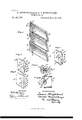
- the improvement relates to that class of window-blinds in which the slats are adapted to work in the stiles by means of caps which are applied to the end of the slats; and the improvement in question consists in the special mode of constructing-and applying the cap, substantially as is hereinafter described and claimed, aided by the annexed drawings, making part of this specification, in which Figure 1 is a View in perspective showing a group of the slats having the improved cap.
- Fig. 2 a view in perspective, looking in the opposite direction to that of Fig. 1, showing one of the slats having the cap applied;
- Fig. 3 a horizontal section showing a portion of one of the blind-stiles and a slat journaled therein, the section being on the line 3 3 of Fig. 4, which in turn is a top view showing the slat and its cap only, said cap being in section and a portion of the slat being broken away to exhibit the interior construction of the cap;
- Fig. 5 a view in perspective similar to that of Fig. 2, showing a modified cap;
- Fig. 6, a view similar to that of Fig. 2, showing modification.
- the slats A are of the customary materialwood-and of the usual shape, saving the slat-journal does not form part thereof.
- 13 represents the improved cap with which each slat is provided. In its general shape it resembles a socket, which is applied to the end of the slat, and it is provided with a journal Z), which constitutes the bearing for the slat in the blind-stile O.
- Said journal preferably works in a metal strip D, which is let into the stile, substantially as shown in Fig. 3, and to provide clearance between the main portion of the cap'and the strip the journal is provided with a shoulder b, substantially as shown.
- the leading features of the improved cap are the flange b or flanges 79 12 which, after the slat has been inserted in the socket of the cap, are embedded in the surfaces of the slat, and the tongue 79 which projects from what might be termed the bottom I) of the cap, and which when the cap and slat are put together is driven into the end of the slat, substantially as shown in Figs. 3 and 4. That is. to properly unite the slat and cap, the cap is provided.
- Said tongue may be of any suitable shape for the purpose in question, and said points, or teeth may also be variously formed.
- the forms exhibited in Figs. 3 and 4 of said tongue and teeth we consider desirable, said tongue being wedge shaped, as shown, and said teeth I) being the ends of the flanges b 12 as shown.
- Fig. 3 one of said teeththe lower one as there seen-is not yet embedded in the slat.
- the upper tooth is embedded in the slat.
- a modification of said teeth is exhibited in Fig. 6, the flanges b b in such modification being serrated in distinction from being made in the form of a continuous single tooth, as shownin Figs. 2 and 3.
- eye E which is formed in the end of the cap out of a piece of wire let into the cap, the cap in practice, including its socket, its journal, flanges, teeth, and tongue, being a casting into which said eye is cast.
- F represents a slat-rod of any suitable shape, which is jointed to the eyes E E E, and by means of which the slats can be turned in their bearings in the lVe c1ain1
- the said cap having the journal, teeth, and tongue, I 5
Landscapes
- Engineering & Computer Science (AREA)
- Civil Engineering (AREA)
- Structural Engineering (AREA)
- Wing Frames And Configurations (AREA)
Description
@72621169 Wh 77m -o- (No Model.)
E. STOEPPELWERTH & O. KNEFELKAMP. WINDOW BLIND.
No. 465,787. Patented Dec. 22, 1891.
Aasli/ Inventors: Q wmi daze/ "7 UNITED STATES PATENT OFFICE.
EDXVARD ."lOEPPEIflV ER'lI'I AND CHARLES KNEFELKAMP, OF ST. LOUIS,
MISSOURI.
WINDOW-BLIND.
SPECIFICATION forming part of Letters Patent No. 465,787, dated December 22, 1891.
Application filed June 8,1891- Serial No. 395,562. (No model.) a
To all whom it may concern:
Be it known that we, EDWARD STOEPPEL- WERTH and CHARLES KNEFELKAMP, of St. Louis, Missouri, have jointly made a new and useful Improvement in indov-Blinds, of which the following is a full, clear, and exact description.
The improvement relates to that class of window-blinds in which the slats are adapted to work in the stiles by means of caps which are applied to the end of the slats; and the improvement in question consists in the special mode of constructing-and applying the cap, substantially as is hereinafter described and claimed, aided by the annexed drawings, making part of this specification, in which Figure 1 is a View in perspective showing a group of the slats having the improved cap.
Only that portion of the slats is shown which is needed for an understanding of the improvement, and the frame-work of the blind is omitted; Fig. 2, a view in perspective, looking in the opposite direction to that of Fig. 1, showing one of the slats having the cap applied; Fig. 3, a horizontal section showing a portion of one of the blind-stiles and a slat journaled therein, the section being on the line 3 3 of Fig. 4, which in turn is a top view showing the slat and its cap only, said cap being in section and a portion of the slat being broken away to exhibit the interior construction of the cap; Fig. 5, a view in perspective similar to that of Fig. 2, showing a modified cap; and Fig. 6, a view similar to that of Fig. 2, showing modification.
The same letters of reference denote the same parts.
The slats A are of the customary materialwood-and of the usual shape, saving the slat-journal does not form part thereof. 13 represents the improved cap with which each slat is provided. In its general shape it resembles a socket, which is applied to the end of the slat, and it is provided with a journal Z), which constitutes the bearing for the slat in the blind-stile O. Said journal preferably works in a metal strip D, which is let into the stile, substantially as shown in Fig. 3, and to provide clearance between the main portion of the cap'and the strip the journal is provided with a shoulder b, substantially as shown. The leading features of the improved cap, however, are the flange b or flanges 79 12 which, after the slat has been inserted in the socket of the cap, are embedded in the surfaces of the slat, and the tongue 79 which projects from what might be termed the bottom I) of the cap, and which when the cap and slat are put together is driven into the end of the slat, substantially as shown in Figs. 3 and 4. That is. to properly unite the slat and cap, the cap is provided. with one or more points or teeth, which, after the slat is in position in the cap, can be and are set into the slat to become interlocked therewith, and to more eifectually accomplish the interlocking the tongue is employed in combination, the tongue operating to spread the slat at its extreme end, and the points or teeth referred to operating to narrow the slat at a point without that portion of the slat acted upon by said tongue. Either of said features-said teeth or said tongueis valuable as a means for better uniting the slat and the cap-that is, said teeth in a measure bind the slat even if the tongue is not used, and said tongue can be advantageouslyemployed in a cap having a socket merely. Ve prefer to use both said features in conjunction, as shown. Said tongue may be of any suitable shape for the purpose in question, and said points, or teeth may also be variously formed. The forms exhibited in Figs. 3 and 4 of said tongue and teeth we consider desirable, said tongue being wedge shaped, as shown, and said teeth I) being the ends of the flanges b 12 as shown. In Fig. 3 one of said teeththe lower one as there seen-is not yet embedded in the slat. The upper tooth is embedded in the slat. A modification of said teeth is exhibited in Fig. 6, the flanges b b in such modification being serrated in distinction from being made in the form of a continuous single tooth, as shownin Figs. 2 and 3.
An additional feature of the cap is the eye E, which is formed in the end of the cap out of a piece of wire let into the cap, the cap in practice, including its socket, its journal, flanges, teeth, and tongue, being a casting into which said eye is cast. F represents a slat-rod of any suitable shape, which is jointed to the eyes E E E, and by means of which the slats can be turned in their bearings in the lVe c1ain1 The combination of the blind-slat and cap,
The said cap having the journal, teeth, and tongue, I 5
and combined with said slat, substantially as described.
'VVitness our hands this 3d day of June,
EDWARD STOEPPELXVERTH. CHARLES KNEFELKAMP. Witnesses:
C. D. MooDY, A. BONVILLE.
Publications (1)
| Publication Number | Publication Date |
|---|---|
| US465787A true US465787A (en) | 1891-12-22 |
Family
ID=2534651
Family Applications (1)
| Application Number | Title | Priority Date | Filing Date |
|---|---|---|---|
| US465787D Expired - Lifetime US465787A (en) | Window-blind |
Country Status (1)
| Country | Link |
|---|---|
| US (1) | US465787A (en) |
Cited By (2)
| Publication number | Priority date | Publication date | Assignee | Title |
|---|---|---|---|---|
| US3191241A (en) * | 1962-10-29 | 1965-06-29 | American Warming Ventilation | Damper blades and means for pivoting same |
| US3591980A (en) * | 1969-02-14 | 1971-07-13 | Hong Kong Chiap Hua Mfg Co 194 | Louvre arrangements |
-
0
- US US465787D patent/US465787A/en not_active Expired - Lifetime
Cited By (2)
| Publication number | Priority date | Publication date | Assignee | Title |
|---|---|---|---|---|
| US3191241A (en) * | 1962-10-29 | 1965-06-29 | American Warming Ventilation | Damper blades and means for pivoting same |
| US3591980A (en) * | 1969-02-14 | 1971-07-13 | Hong Kong Chiap Hua Mfg Co 194 | Louvre arrangements |
Similar Documents
| Publication | Publication Date | Title |
|---|---|---|
| US960085A (en) | Hinge. | |
| US1115557A (en) | Repairable gearing for looms. | |
| US197583A (en) | Improvement in blinds | |
| US1050699A (en) | Door or window closure. | |
| US670368A (en) | Pivoted anchor. | |
| US477512A (en) | Awning | |
| US1101582A (en) | Metal sash. | |
| US214926A (en) | Improvement in window-shades | |
| US1225727A (en) | Joint for sash-bars. | |
| US1927423A (en) | Window and weather strip for windows | |
| US538466A (en) | Window | |
| US629680A (en) | Window shutter or blind. | |
| US370699A (en) | Eugene p | |
| US387698A (en) | William a | |
| US1292556A (en) | Bolt. | |
| US67363A (en) | lumis | |
| US1097477A (en) | Window-shade roller. | |
| US999802A (en) | Reversible window-sash. | |
| US837734A (en) | Fireproof door. | |
| US900336A (en) | Shutter-hinge. | |
| US1045625A (en) | Reversible window. | |
| US627165A (en) | Reversible window | |
| US1211037A (en) | Dust-guard. | |
| US160278A (en) | Improvement in curtain-fixtures | |
| US1135349A (en) | Hinge. |