US4644162A - Cooling hole inspection - Google Patents
Cooling hole inspection Download PDFInfo
- Publication number
- US4644162A US4644162A US06/652,245 US65224584A US4644162A US 4644162 A US4644162 A US 4644162A US 65224584 A US65224584 A US 65224584A US 4644162 A US4644162 A US 4644162A
- Authority
- US
- United States
- Prior art keywords
- channels
- channel
- transient
- holes
- blade
- Prior art date
- Legal status (The legal status is an assumption and is not a legal conclusion. Google has not performed a legal analysis and makes no representation as to the accuracy of the status listed.)
- Expired - Lifetime
Links
- 238000001816 cooling Methods 0.000 title claims abstract description 14
- 238000007689 inspection Methods 0.000 title description 7
- 230000001052 transient effect Effects 0.000 claims abstract description 12
- 230000005855 radiation Effects 0.000 claims description 3
- 238000000034 method Methods 0.000 claims 3
- 230000005457 Black-body radiation Effects 0.000 claims 1
- 239000000956 alloy Substances 0.000 description 4
- 229910045601 alloy Inorganic materials 0.000 description 4
- 238000005219 brazing Methods 0.000 description 4
- 239000000463 material Substances 0.000 description 4
- 239000000523 sample Substances 0.000 description 3
- 239000011248 coating agent Substances 0.000 description 2
- 238000000576 coating method Methods 0.000 description 2
- 238000005259 measurement Methods 0.000 description 2
- 230000003247 decreasing effect Effects 0.000 description 1
- 230000007547 defect Effects 0.000 description 1
- 238000002347 injection Methods 0.000 description 1
- 239000007924 injection Substances 0.000 description 1
- 238000003780 insertion Methods 0.000 description 1
- 230000037431 insertion Effects 0.000 description 1
- 238000012986 modification Methods 0.000 description 1
- 230000004048 modification Effects 0.000 description 1
- 238000006467 substitution reaction Methods 0.000 description 1
- 230000000007 visual effect Effects 0.000 description 1
Images

Classifications
-
- G—PHYSICS
- G01—MEASURING; TESTING
- G01N—INVESTIGATING OR ANALYSING MATERIALS BY DETERMINING THEIR CHEMICAL OR PHYSICAL PROPERTIES
- G01N25/00—Investigating or analyzing materials by the use of thermal means
- G01N25/72—Investigating presence of flaws
Definitions
- the present invention relates to the inspection of holes to determine that they have been properly manufactured and, more specifically, to the inspection of cooling channels in gas turbine engine blades.
- Gas turbine engine blades contain channels which lead from an exterior surface to an interior plenum.
- An example is shown in FIG. 1, wherein a blade 2 contains a plenum 3 to which channels 6 connect and lead to an external surface 9.
- pressurized air is applied to the plenum 3 causing cooling airstreams 12 to flow through the channels 6, thereby absorbing heat from the walls of the channels 6, as well as from the surface 9 of the blade 2, thereby cooling the blade 2.
- the channels 6 In order to function properly, the channels 6 must be constructed to a known configuration because the distribution of airflow must be controlled in order to achieve proper cooling. Restated, the channels 6 must not be blocked, not even partially. However, inspection of channels 6 to detect blockages from the external surface 9 is difficult. One reason is that they are very small, a typical diameter being 12 mils (0.3 mm), and thus it is nearly impossible to insert a diameter measurement gage into the channels 6.
- FIG. 1 illustrates a gas turbine engine blade of the type examined by the present invention.
- FIG. 2 illustrates one form of the present invention.
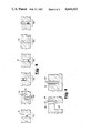
- FIG. 3 illustrates six different types of cooling holes and defects which can be contained by the blade in FIG. 1.
- FIG. 4 illustrates a depth measurement of two of the holes in FIG. 3.
- the temperatures of cooling passages in a gas turbine engine blade are changed, as by forcing a heated gas through them.
- the infrared signatures of the channels are measured during the initial temperature transient of the channels and the signatures are compared with a reference.
- the reference may be the signature of other channels on the same blade.
- FIG. 2 illustrates one form of the present invention, wherein line 15 receives filtered, compressed air and delivers it to point 18 at which the air is fed to the internal plenum 3 contained in the gas turbine engine blade 2.
- the blade 2 is held by a fixture 19.
- Interconnected in line 15 is a pressure regulator 21, an air heater 23, a solenoid valve 24, and a pressure gage 27.
- a computerized control 30, known in the art controls the air heater 23 and the solenoid valve 24 by respective electrical lines 33 and 36.
- a scanning infrared radiometer 39 herein called an IR camera, such as Model No.
- an operator will mount the turbine blade in the fixture 19 and activate the control 30 through a switch 57.
- the control opens the solenoid 24 and activates the heater 23 to admit a heated airstream (not specifically shown) to the plenum 3.
- the heated airstream causes the channels 6, when they are very small (less than 0.035 inches (0.89 mm) in diameter), to act as black body cavity radiators. As such, they approach behaving as idealized sources of radiation in accordance with Planck's well known, empirically ascertained law. Applicants utilize this finding in examining channels 6 for blockages as follows.
- Region 70A contains a properly formed channel 6A.
- Region 70B contains a channel which contains a "jink" caused by two adjacent sharp turns 73 and 76. (Because of details which need not be understood by the reader, walls 73A and 76A tend to be co-linear when a jink is formed.)
- Region 70C contains an improperly drilled channel 6C which is blocked at its bottom.
- Region 70D contains a brazed-over channel 6D which is capped by a cap 79 of brazing alloy or blade coating material.
- the fifth type of blockage is shown in region 70E and it is a blockage in which no channel, not even a partial one, exists.
- Region 70F contains a partially blocked channel 6F containing a blockage 83.
- the situations in the two regions 70D and F can result from mishaps in which brazing alloy accidentally overflows and forms the cap 79 in region 70D, or in which it overflows and forms the blockage 83 in region 70F.
- Brazing alloy is sometimes used to fasten a tip cap 85 in FIG. 1 to a blade 2. Further, the braze alloy or other coating material itself can sometimes form a cap 79 in region 6D in FIG. 3.
- Some of the six blockages have been found to be distinguishable from the others based on their infrared signatures, as detected by the IR camera 39 in FIG. 2.
- the channels 6A-E in FIG. 3 radiate with intensities of decreasing magnitude from left to right in the Figure: channel 6A is the brightest and channel 6E is the dimmest. (Channel 6F is not now being considered.)
- the three channels 6A, B and C are about equally bright, channel 6D is less bright, and the absent channel 6E in region 70E radiates at the same level as the rest of the background.
- the blocked channel 6C is distinguishable from the open channel 6A, as is the jinked channel 6B.
- the capped channel 6D begins to radiate similar to 6A, 6B and 6C following the initial transient because of the emissivity of the brazing material of which the cap 79 is constructed. This similarity allows channel 6D to be distinguished from the absent channel in region 70E.
- the channel cap radiates more because of its increased temperature.
- the absent channel and the capped channel 6D could otherwise look similar to a visual observer.
- the results show that the jinked channel 6B in fact carries cooling air and may be usable as a cooling channel in a blade.
- Applicants have not been able to obtain blockages 83 in channel 6F as shown in FIG. 3. However, based on Applicants' experience with the rest of the channels in FIG. 3, Applicants theorize that the partially blocked channel 6F will radiate slightly less than the open channel 6A during the transient. Further, the partially blocked channel 6F should radiate almost equally as the open channel 6A following the transient. Thus, the combination of the transient radiance and the steady-state radiance (i.e., radiance less than that of the clear channel 6A at first, followed by radiance greater than that of the jinked channel 6B or the blocked channel 6C), indicates the presence of partial blockage 83.
- the steady-state radiance i.e., radiance less than that of the clear channel 6A at first, followed by radiance greater than that of the jinked channel 6B or the blocked channel 6C
- the present invention contemplates the use of cold air passing through a relatively warm channel.
- the important aspect is that the temperature, and thus the emissivity, of the channels 6A-F in FIG. 3 be rendered different than that of the surface material 9.
- obstructions in a channel are ascertained by measuring the infrared signature of the channel when a heated (or cooled) gas, such as air, is forced through it, and, specifically, the infrared signature occurring during the initial transient phase of the air injection.
- the infrared signatures are compared with each other but, of course, they may be compared with another reference, such as a photograph of previously examined channels.
Landscapes
- Physics & Mathematics (AREA)
- Health & Medical Sciences (AREA)
- Life Sciences & Earth Sciences (AREA)
- Chemical & Material Sciences (AREA)
- Analytical Chemistry (AREA)
- Biochemistry (AREA)
- General Health & Medical Sciences (AREA)
- General Physics & Mathematics (AREA)
- Immunology (AREA)
- Pathology (AREA)
- Investigating Or Analyzing Materials Using Thermal Means (AREA)
- Radiation Pyrometers (AREA)
- Length Measuring Devices With Unspecified Measuring Means (AREA)
- Testing Of Devices, Machine Parts, Or Other Structures Thereof (AREA)
- Length Measuring Devices By Optical Means (AREA)
- Measuring Arrangements Characterized By The Use Of Fluids (AREA)
Abstract
In the present invention, the temperatures of cooling passages in a gas turbine engine blade are changed, as by forcing a heated gas through them. The infrared signatures of the channels are measured during the initial temperature transient of the channels and the signatures are compared with a reference. The reference may be the signature of other channels on the same blade.
Description
The Government has rights in this invention pursuant to Contract No. F33615-80-C-5106 awarded by the Department of the Air Force.
The present invention relates to the inspection of holes to determine that they have been properly manufactured and, more specifically, to the inspection of cooling channels in gas turbine engine blades.
Gas turbine engine blades contain channels which lead from an exterior surface to an interior plenum. An example is shown in FIG. 1, wherein a blade 2 contains a plenum 3 to which channels 6 connect and lead to an external surface 9. In use, pressurized air is applied to the plenum 3 causing cooling airstreams 12 to flow through the channels 6, thereby absorbing heat from the walls of the channels 6, as well as from the surface 9 of the blade 2, thereby cooling the blade 2.
In order to function properly, the channels 6 must be constructed to a known configuration because the distribution of airflow must be controlled in order to achieve proper cooling. Restated, the channels 6 must not be blocked, not even partially. However, inspection of channels 6 to detect blockages from the external surface 9 is difficult. One reason is that they are very small, a typical diameter being 12 mils (0.3 mm), and thus it is nearly impossible to insert a diameter measurement gage into the channels 6.
It is an object of the present invention to provide a new and improved inspection apparatus for inspecting channels.
It is a further object of the present invention to provide new and improved inspection system for the inspection of cooling channels in gas turbine engine blades.
FIG. 1 illustrates a gas turbine engine blade of the type examined by the present invention.
FIG. 2 illustrates one form of the present invention.
FIG. 3 illustrates six different types of cooling holes and defects which can be contained by the blade in FIG. 1.
FIG. 4 illustrates a depth measurement of two of the holes in FIG. 3.
In one form of the present invention, the temperatures of cooling passages in a gas turbine engine blade are changed, as by forcing a heated gas through them. The infrared signatures of the channels are measured during the initial temperature transient of the channels and the signatures are compared with a reference. The reference may be the signature of other channels on the same blade.
FIG. 2 illustrates one form of the present invention, wherein line 15 receives filtered, compressed air and delivers it to point 18 at which the air is fed to the internal plenum 3 contained in the gas turbine engine blade 2. The blade 2 is held by a fixture 19. Interconnected in line 15 is a pressure regulator 21, an air heater 23, a solenoid valve 24, and a pressure gage 27. A computerized control 30, known in the art, controls the air heater 23 and the solenoid valve 24 by respective electrical lines 33 and 36. A scanning infrared radiometer 39, herein called an IR camera, such as Model No. 525, available from inframetrics, located in Bedford, MA., takes an image of the channels 6 through which the heated air provided at point 18 is escaping, and transmits a signal along electrical line 42 to an electronics package 45, available from Inframetrics, whih is associated with Model No. 525, which transmits signals to a video monitor 47 along line 50. This scanning radiometer is responsive to radiation in approximately the 9-12 micron range. A representative image 53 is shown on the monitor.
In operation, an operator will mount the turbine blade in the fixture 19 and activate the control 30 through a switch 57. The control opens the solenoid 24 and activates the heater 23 to admit a heated airstream (not specifically shown) to the plenum 3.
Applicants have found that the heated airstream causes the channels 6, when they are very small (less than 0.035 inches (0.89 mm) in diameter), to act as black body cavity radiators. As such, they approach behaving as idealized sources of radiation in accordance with Planck's well known, empirically ascertained law. Applicants utilize this finding in examining channels 6 for blockages as follows.
Six different types of blockage are shown in FIG. 3 in six different regions 70A-F. Region 70A contains a properly formed channel 6A. Region 70B contains a channel which contains a "jink" caused by two adjacent sharp turns 73 and 76. (Because of details which need not be understood by the reader, walls 73A and 76A tend to be co-linear when a jink is formed.) Region 70C contains an improperly drilled channel 6C which is blocked at its bottom. Region 70D contains a brazed-over channel 6D which is capped by a cap 79 of brazing alloy or blade coating material. The fifth type of blockage is shown in region 70E and it is a blockage in which no channel, not even a partial one, exists. The fully blocked channel is designated 6E for reference. Region 70F contains a partially blocked channel 6F containing a blockage 83. (The situations in the two regions 70D and F can result from mishaps in which brazing alloy accidentally overflows and forms the cap 79 in region 70D, or in which it overflows and forms the blockage 83 in region 70F. Brazing alloy is sometimes used to fasten a tip cap 85 in FIG. 1 to a blade 2. Further, the braze alloy or other coating material itself can sometimes form a cap 79 in region 6D in FIG. 3.) Some of the six blockages have been found to be distinguishable from the others based on their infrared signatures, as detected by the IR camera 39 in FIG. 2.
For example, during the initial transient, immediately following the introduction of hot air (preferably at 200° F. (370 K.) or higher) into the plenum 3 of the blade 2, the channels 6A-E in FIG. 3 radiate with intensities of decreasing magnitude from left to right in the Figure: channel 6A is the brightest and channel 6E is the dimmest. (Channel 6F is not now being considered.) After about two seconds, the three channels 6A, B and C are about equally bright, channel 6D is less bright, and the absent channel 6E in region 70E radiates at the same level as the rest of the background.
Several important pieces of information are available from these differences in brightness. One, during the transient, the blocked channel 6C is distinguishable from the open channel 6A, as is the jinked channel 6B. Two, the capped channel 6D begins to radiate similar to 6A, 6B and 6C following the initial transient because of the emissivity of the brazing material of which the cap 79 is constructed. This similarity allows channel 6D to be distinguished from the absent channel in region 70E. The channel cap radiates more because of its increased temperature. The absent channel and the capped channel 6D could otherwise look similar to a visual observer. Three, the results show that the jinked channel 6B in fact carries cooling air and may be usable as a cooling channel in a blade. An observer examining the jinked channel 6B with a needle probe 88 in FIG. 4 would probably confuse the jinked channel 6B with the blocked channel 6C, in that insertion of the needle probe 88 would be similarly thwarted in both channels. The observer using the needle probe 88 would probably classify the jinked channel 6B as a blocked channel 6C and conclude that the jinked channel 6B carries no cooling air.
Applicants have not been able to obtain blockages 83 in channel 6F as shown in FIG. 3. However, based on Applicants' experience with the rest of the channels in FIG. 3, Applicants theorize that the partially blocked channel 6F will radiate slightly less than the open channel 6A during the transient. Further, the partially blocked channel 6F should radiate almost equally as the open channel 6A following the transient. Thus, the combination of the transient radiance and the steady-state radiance (i.e., radiance less than that of the clear channel 6A at first, followed by radiance greater than that of the jinked channel 6B or the blocked channel 6C), indicates the presence of partial blockage 83.
Although the use of hot air passing through a cold channel has been described, the present invention contemplates the use of cold air passing through a relatively warm channel. The important aspect is that the temperature, and thus the emissivity, of the channels 6A-F in FIG. 3 be rendered different than that of the surface material 9.
An invention has been described wherein obstructions in a channel are ascertained by measuring the infrared signature of the channel when a heated (or cooled) gas, such as air, is forced through it, and, specifically, the infrared signature occurring during the initial transient phase of the air injection. The infrared signatures are compared with each other but, of course, they may be compared with another reference, such as a photograph of previously examined channels.
Numerous substitutions and modifications can be undertaken without departing from the true spirit and scope of the present invention.
What is desired to be secured by Letters Patent is the invention as defined in the following claims.
Claims (3)
1. A method of inspecting a channel, comprising the following steps:
(a) causing the temperature of the channel to change;
(b) measuring the transient of the infrared signature of the channel; and
(c) comparing the measured transient with a reference.
2. A method of inspecting cooling channels in a gas turbine engine blade, comprising the following steps:
(a) changing the temperature of the channels by forcing a gas through the channels;
(b) viewing the channels with a scanning infrared radiometer and generating an image which indicates the relative intensities of black-body radiation emitted by the channels; and
(c) comparing the intensities of paragraph (b) with each other during the initial temperature transient of the channels.
3. A method of inspecting the cooling holes in a gas turbine engine blade, comprising the steps of:
(a) changing the temperatures of the holes by passing air through them;
(b) viewing the holes using a scanning radiometer which is responsive to radiation in approximately the 9-12 micron range;
(c) deriving at least two images at different times of the holes using the radiometer; and
(d) comparing the images with reference images.
Priority Applications (6)
| Application Number | Priority Date | Filing Date | Title |
|---|---|---|---|
| US06/652,245 US4644162A (en) | 1984-09-20 | 1984-09-20 | Cooling hole inspection |
| GB8521481A GB2164746B (en) | 1984-09-20 | 1985-08-29 | Cooling hole inspection |
| FR858513680A FR2570498B1 (en) | 1984-09-20 | 1985-09-16 | METHOD OF INSPECTING COOLING HOLES, PARTICULARLY COOLING CHANNELS OF TURBINE BLADES |
| DE19853533186 DE3533186A1 (en) | 1984-09-20 | 1985-09-18 | COOLING HOLE TEST METHOD |
| IT22210/85A IT1185354B (en) | 1984-09-20 | 1985-09-19 | INSPECTION METHODS FOR COOLING HOLES ESPECIALLY IN TURBINE BLADES |
| JP60206763A JPH0619260B2 (en) | 1984-09-20 | 1985-09-20 | Cooling hole inspection method |
Applications Claiming Priority (1)
| Application Number | Priority Date | Filing Date | Title |
|---|---|---|---|
| US06/652,245 US4644162A (en) | 1984-09-20 | 1984-09-20 | Cooling hole inspection |
Publications (1)
| Publication Number | Publication Date |
|---|---|
| US4644162A true US4644162A (en) | 1987-02-17 |
Family
ID=24616104
Family Applications (1)
| Application Number | Title | Priority Date | Filing Date |
|---|---|---|---|
| US06/652,245 Expired - Lifetime US4644162A (en) | 1984-09-20 | 1984-09-20 | Cooling hole inspection |
Country Status (6)
| Country | Link |
|---|---|
| US (1) | US4644162A (en) |
| JP (1) | JPH0619260B2 (en) |
| DE (1) | DE3533186A1 (en) |
| FR (1) | FR2570498B1 (en) |
| GB (1) | GB2164746B (en) |
| IT (1) | IT1185354B (en) |
Cited By (42)
| Publication number | Priority date | Publication date | Assignee | Title |
|---|---|---|---|---|
| FR2630209A1 (en) * | 1988-04-13 | 1989-10-20 | Gen Electric | DEVICE AND METHOD FOR MEASURING THERMAL PERFORMANCE OF A HEATED OR COOLED COMPONENT |
| US4916715A (en) * | 1988-04-13 | 1990-04-10 | General Electric Company | Method and apparatus for measuring the distribution of heat flux and heat transfer coefficients on the surface of a cooled component used in a high temperature environment |
| US4978230A (en) * | 1988-04-13 | 1990-12-18 | General Electric Company | Apparatus and method for determining heat transfer coefficient based on testing actual hardware rather than simplistic scale models of such hardware |
| US4983836A (en) * | 1988-06-30 | 1991-01-08 | Nkk Corporation | Method for detecting thinned out portion on inner surface or outer surface of pipe |
| US5111046A (en) * | 1991-03-18 | 1992-05-05 | General Electric Company | Apparatus and method for inspecting cooling holes |
| WO1993022663A1 (en) * | 1992-05-01 | 1993-11-11 | Exid, Inc. | Contactless testing of electronic materials and devices using microwave radiation |
| US5275489A (en) * | 1992-10-19 | 1994-01-04 | General Electric Company | Apparatus and method for inspecting an open-face cell structure bonded to a substrate |
| US5562345A (en) * | 1992-05-05 | 1996-10-08 | The United States Of America As Represented By The Administrator Of The National Aeronautics And Space Administration | Method and apparatus for thermographically and quantitatively analyzing a structure for disbonds and/or inclusions |
| US5773790A (en) * | 1997-01-21 | 1998-06-30 | General Electric Company | Beam blocking material and method for beam drilling and inspecting cooling holes |
| US6422743B1 (en) * | 1999-03-26 | 2002-07-23 | Allison Advanced Development Company | Method for determining heat transfer performance of an internally cooled structure |
| US20020122458A1 (en) * | 2000-12-28 | 2002-09-05 | Ingallinera Michael David | Utilization of pyrometer data to detect oxidation |
| US6570175B2 (en) | 2001-11-01 | 2003-05-27 | Computerized Thermal Imaging, Inc. | Infrared imaging arrangement for turbine component inspection system |
| US20030103836A1 (en) * | 2001-12-04 | 2003-06-05 | Beaulieu David R. | Substrate processing apparatus with independently configurable integral load locks |
| WO2003038238A3 (en) * | 2001-11-01 | 2003-11-20 | Computerized Thermal Imaging I | Turbine component inspection system |
| US20040037344A1 (en) * | 2002-08-23 | 2004-02-26 | Bunker Ronald Scott | Method for quantifying film hole flow rates for film-cooled parts |
| US6711506B2 (en) | 2001-11-21 | 2004-03-23 | Computerized Thermal Imaging, Inc. | Computerized operator assistance for turbine component inspection |
| EP1416266A1 (en) * | 2002-11-04 | 2004-05-06 | Siemens Aktiengesellschaft | Method for inspecting the structure of through-holes of a material |
| US6750454B2 (en) | 2001-11-21 | 2004-06-15 | Computerized Thermal Imaging, Inc. | Automated analysis of turbine component thermal response |
| US6804622B2 (en) | 2001-09-04 | 2004-10-12 | General Electric Company | Method and apparatus for non-destructive thermal inspection |
| US20070290134A1 (en) * | 2005-12-07 | 2007-12-20 | Meyer Tool, Inc. | Apparatus and Method for Analyzing Relative Outward Flow Characterizations of Fabricated Features |
| US20080237466A1 (en) * | 2006-06-14 | 2008-10-02 | Meyer Tool, Inc. | Apparatus and Method for Analyzing Relative Outward Flow Characterizations of Fabricated Features |
| US20090016402A1 (en) * | 2007-07-10 | 2009-01-15 | General Electric Company | System and method for thermal inspection of parts |
| US20090255332A1 (en) * | 2008-04-11 | 2009-10-15 | General Electric Company | Thermal inspection system and method |
| US20090297336A1 (en) * | 2007-08-21 | 2009-12-03 | General Electric Company | Online systems and methods for thermal inspection of parts |
| US20100250155A1 (en) * | 2009-03-30 | 2010-09-30 | General Electric Company | Method for quantifying hole flow rates in film cooled parts |
| US20110048117A1 (en) * | 2009-08-27 | 2011-03-03 | Rolls-Royce Plc | Inspection of holes |
| DE102009039224A1 (en) | 2009-08-28 | 2011-03-03 | Mtu Aero Engines Gmbh | Method for recognizing blocked bore-hole in metallic component i.e. vane of high pressure turbo engine in gas turbine system, involves recognizing continuous borehole based on temperature change in bore-hole |
| US20110125423A1 (en) * | 2009-11-25 | 2011-05-26 | General Electric Company | Thermal inspection systems |
| US20110164653A1 (en) * | 2010-01-07 | 2011-07-07 | General Electric Company | Thermal inspection system and method incorporating external flow |
| US20110235672A1 (en) * | 2010-03-17 | 2011-09-29 | Thermal Wave Imaging, Inc. | Thermographic Detection of Internal Passageway Blockages |
| DE102012206103B3 (en) * | 2012-04-13 | 2013-07-18 | Block Materialprüfungs-Gesellschaft mbH | A method for determining the extent of damage of impact damage on a surface of a body |
| US8810644B2 (en) | 2010-12-15 | 2014-08-19 | General Electric Company | Thermal inspection and machining systems and methods of use |
| US20150033836A1 (en) * | 2013-08-02 | 2015-02-05 | Pratt & Whitney Canada Corp. | Methods and apparatus for inspecting cooling holes |
| US9080453B2 (en) | 2010-03-17 | 2015-07-14 | Thermal Wave Imaging, Inc. | Thermographic detection of internal passageway blockages |
| US20160177772A1 (en) * | 2014-03-07 | 2016-06-23 | United Technologies Corporation | Thermal inspection system |
| US10104313B2 (en) | 2016-07-08 | 2018-10-16 | United Technologies Corporation | Method for turbine component qualification |
| CN109751972A (en) * | 2019-03-01 | 2019-05-14 | 北京金轮坤天特种机械有限公司 | The cooling air film hole detection platform of high-pressure turbine working blade and test method |
| US10551327B2 (en) | 2018-04-11 | 2020-02-04 | General Electric Company | Cooling hole inspection system |
| US10810730B2 (en) | 2013-03-12 | 2020-10-20 | Rolls-Royce Corporation | Nondestructive testing of a component |
| CN113958371A (en) * | 2020-07-21 | 2022-01-21 | 通用电气公司 | Cooling hole inspection system |
| US11340184B2 (en) | 2018-11-05 | 2022-05-24 | General Electric Company | Engine component performance inspection sleeve and method of inspecting engine component |
| US11885688B2 (en) | 2020-07-21 | 2024-01-30 | General Electric Company | Method and system for inspecting cooling holes of a turbine engine component |
Families Citing this family (10)
| Publication number | Priority date | Publication date | Assignee | Title |
|---|---|---|---|---|
| US4886370A (en) * | 1987-08-25 | 1989-12-12 | Nkk Corporation | Method for detecting a state of substance existing in pipe |
| JPH0658211B2 (en) * | 1988-02-24 | 1994-08-03 | 富士電機株式会社 | Mark sensor |
| FR2671184B1 (en) * | 1990-12-28 | 1994-05-13 | Propulsion Ste Europeenne | METHOD AND DEVICE FOR CONTROLLING A FILTER ELEMENT BY INFRARED RADIATION. |
| DE19537999A1 (en) * | 1995-10-12 | 1997-04-17 | Bmw Rolls Royce Gmbh | Image acquisition method for thermally stressed components, in particular a gas turbine |
| GB9805861D0 (en) * | 1998-03-20 | 1998-05-13 | Rolls Royce Plc | A method and an apparatus for inspecting articles |
| US7095495B2 (en) * | 2003-01-31 | 2006-08-22 | General Electric Company | Fluorescent inspection of airfoil cooling holes |
| DE102008013839A1 (en) * | 2008-03-12 | 2009-09-17 | Volkswagen Ag | Component's i.e. motor vehicle pedal, hollow space inspecting method, involves photo-optically documenting hollow spaces, and comparing reference component photo and to-be-inspected component photo with each other |
| DE102010047713B4 (en) * | 2009-10-12 | 2015-09-17 | BAM Bundesanstalt für Materialforschung und -prüfung | Measuring arrangement and method for the quantitative detection of spatial distributions of gas flows |
| DE102010004673A1 (en) * | 2010-01-08 | 2011-07-14 | Block Materialprüfungs-Gesellschaft mbH, 13629 | Method for measuring of gas flow behavior of hollow body, involves feeding gas into hollow body, and closing exit hole when measured temperature change in hollow body surface area meets predetermined criterion |
| JP7710527B2 (en) * | 2021-11-15 | 2025-07-18 | 三菱重工業株式会社 | Component inspection method, component manufacturing method, and component inspection device |
Citations (2)
| Publication number | Priority date | Publication date | Assignee | Title |
|---|---|---|---|---|
| US3566669A (en) * | 1968-09-04 | 1971-03-02 | Harry Parker | Method and apparatus for thermally examining fluid passages in a body |
| GB2125556A (en) * | 1982-08-19 | 1984-03-07 | Gen Electric | Fluid pressure sensor subjected to thermal effect of fluid jets |
Family Cites Families (3)
| Publication number | Priority date | Publication date | Assignee | Title |
|---|---|---|---|---|
| US3803413A (en) * | 1972-05-01 | 1974-04-09 | Vanzetti Infrared Computer Sys | Infrared non-contact system for inspection of infrared emitting components in a device |
| JPS4938154A (en) * | 1972-08-14 | 1974-04-09 | ||
| US3868508A (en) * | 1973-10-30 | 1975-02-25 | Westinghouse Electric Corp | Contactless infrared diagnostic test system |
-
1984
- 1984-09-20 US US06/652,245 patent/US4644162A/en not_active Expired - Lifetime
-
1985
- 1985-08-29 GB GB8521481A patent/GB2164746B/en not_active Expired
- 1985-09-16 FR FR858513680A patent/FR2570498B1/en not_active Expired
- 1985-09-18 DE DE19853533186 patent/DE3533186A1/en not_active Ceased
- 1985-09-19 IT IT22210/85A patent/IT1185354B/en active
- 1985-09-20 JP JP60206763A patent/JPH0619260B2/en not_active Expired - Lifetime
Patent Citations (2)
| Publication number | Priority date | Publication date | Assignee | Title |
|---|---|---|---|---|
| US3566669A (en) * | 1968-09-04 | 1971-03-02 | Harry Parker | Method and apparatus for thermally examining fluid passages in a body |
| GB2125556A (en) * | 1982-08-19 | 1984-03-07 | Gen Electric | Fluid pressure sensor subjected to thermal effect of fluid jets |
Non-Patent Citations (6)
| Title |
|---|
| "Infrared Scanner Detects Coating Defects", Materials Engineering, Oct. 1983, p. 24. |
| "Thermal Diffusivity Measures Thin Films", Lasers & Applications, May 1984, p. 36. |
| Document entitled Tech Update containing article entitled "British Seek Way to Test Composites". |
| Document entitled Tech Update containing article entitled British Seek Way to Test Composites . * |
| Infrared Scanner Detects Coating Defects , Materials Engineering, Oct. 1983, p. 24. * |
| Thermal Diffusivity Measures Thin Films , Lasers & Applications, May 1984, p. 36. * |
Cited By (64)
| Publication number | Priority date | Publication date | Assignee | Title |
|---|---|---|---|---|
| FR2630209A1 (en) * | 1988-04-13 | 1989-10-20 | Gen Electric | DEVICE AND METHOD FOR MEASURING THERMAL PERFORMANCE OF A HEATED OR COOLED COMPONENT |
| US4902139A (en) * | 1988-04-13 | 1990-02-20 | General Electric Company | Apparatus and method for measuring the thermal performance of a heated or cooled component |
| US4916715A (en) * | 1988-04-13 | 1990-04-10 | General Electric Company | Method and apparatus for measuring the distribution of heat flux and heat transfer coefficients on the surface of a cooled component used in a high temperature environment |
| US4978230A (en) * | 1988-04-13 | 1990-12-18 | General Electric Company | Apparatus and method for determining heat transfer coefficient based on testing actual hardware rather than simplistic scale models of such hardware |
| US4983836A (en) * | 1988-06-30 | 1991-01-08 | Nkk Corporation | Method for detecting thinned out portion on inner surface or outer surface of pipe |
| US5111046A (en) * | 1991-03-18 | 1992-05-05 | General Electric Company | Apparatus and method for inspecting cooling holes |
| WO1993022663A1 (en) * | 1992-05-01 | 1993-11-11 | Exid, Inc. | Contactless testing of electronic materials and devices using microwave radiation |
| US5417494A (en) * | 1992-05-01 | 1995-05-23 | Exid, Inc. | Contactless testing of electronic materials and devices using microwaves |
| US5562345A (en) * | 1992-05-05 | 1996-10-08 | The United States Of America As Represented By The Administrator Of The National Aeronautics And Space Administration | Method and apparatus for thermographically and quantitatively analyzing a structure for disbonds and/or inclusions |
| US5275489A (en) * | 1992-10-19 | 1994-01-04 | General Electric Company | Apparatus and method for inspecting an open-face cell structure bonded to a substrate |
| US5773790A (en) * | 1997-01-21 | 1998-06-30 | General Electric Company | Beam blocking material and method for beam drilling and inspecting cooling holes |
| US6422743B1 (en) * | 1999-03-26 | 2002-07-23 | Allison Advanced Development Company | Method for determining heat transfer performance of an internally cooled structure |
| US20020122458A1 (en) * | 2000-12-28 | 2002-09-05 | Ingallinera Michael David | Utilization of pyrometer data to detect oxidation |
| US6579005B2 (en) * | 2000-12-28 | 2003-06-17 | General Electric Company | Utilization of pyrometer data to detect oxidation |
| EP1227222A3 (en) * | 2000-12-28 | 2004-01-02 | General Electric Company | Utilization of pyrometer data to detect oxidation |
| US6804622B2 (en) | 2001-09-04 | 2004-10-12 | General Electric Company | Method and apparatus for non-destructive thermal inspection |
| WO2003038238A3 (en) * | 2001-11-01 | 2003-11-20 | Computerized Thermal Imaging I | Turbine component inspection system |
| US6570175B2 (en) | 2001-11-01 | 2003-05-27 | Computerized Thermal Imaging, Inc. | Infrared imaging arrangement for turbine component inspection system |
| US6711506B2 (en) | 2001-11-21 | 2004-03-23 | Computerized Thermal Imaging, Inc. | Computerized operator assistance for turbine component inspection |
| US6750454B2 (en) | 2001-11-21 | 2004-06-15 | Computerized Thermal Imaging, Inc. | Automated analysis of turbine component thermal response |
| US20030103836A1 (en) * | 2001-12-04 | 2003-06-05 | Beaulieu David R. | Substrate processing apparatus with independently configurable integral load locks |
| US20040037344A1 (en) * | 2002-08-23 | 2004-02-26 | Bunker Ronald Scott | Method for quantifying film hole flow rates for film-cooled parts |
| US6732582B2 (en) | 2002-08-23 | 2004-05-11 | General Electric Company | Method for quantifying film hole flow rates for film-cooled parts |
| EP1416266A1 (en) * | 2002-11-04 | 2004-05-06 | Siemens Aktiengesellschaft | Method for inspecting the structure of through-holes of a material |
| WO2004046700A1 (en) * | 2002-11-04 | 2004-06-03 | Siemens Aktiengesellschaft | Method for examining the structure of through holes of a component |
| US20050173636A1 (en) * | 2002-11-04 | 2005-08-11 | Roman Beyer | Method for examining the structure of through-holes of a component |
| US7075083B2 (en) | 2002-11-04 | 2006-07-11 | Siemens Aktiengesellschaft | Method for examining the structure of through-holes of a component |
| US7388204B2 (en) | 2005-12-07 | 2008-06-17 | Meyer Tool, Inc. | Apparatus and method for analyzing relative outward flow characterizations of fabricated features |
| US20070290134A1 (en) * | 2005-12-07 | 2007-12-20 | Meyer Tool, Inc. | Apparatus and Method for Analyzing Relative Outward Flow Characterizations of Fabricated Features |
| US20080237466A1 (en) * | 2006-06-14 | 2008-10-02 | Meyer Tool, Inc. | Apparatus and Method for Analyzing Relative Outward Flow Characterizations of Fabricated Features |
| US7671338B2 (en) | 2006-06-14 | 2010-03-02 | Meyer Tool, Inc. | Apparatus and method for analyzing relative outward flow characterizations of fabricated features |
| US20090016402A1 (en) * | 2007-07-10 | 2009-01-15 | General Electric Company | System and method for thermal inspection of parts |
| US7651261B2 (en) | 2007-07-10 | 2010-01-26 | General Electric Company | System and method for thermal inspection of parts |
| US20090297336A1 (en) * | 2007-08-21 | 2009-12-03 | General Electric Company | Online systems and methods for thermal inspection of parts |
| US20090255332A1 (en) * | 2008-04-11 | 2009-10-15 | General Electric Company | Thermal inspection system and method |
| US7909507B2 (en) | 2008-04-11 | 2011-03-22 | General Electric Company | Thermal inspection system and method |
| US20100250155A1 (en) * | 2009-03-30 | 2010-09-30 | General Electric Company | Method for quantifying hole flow rates in film cooled parts |
| US7890274B2 (en) * | 2009-03-30 | 2011-02-15 | General Electric Company | Method for quantifying hole flow rates in film cooled parts |
| US20110048117A1 (en) * | 2009-08-27 | 2011-03-03 | Rolls-Royce Plc | Inspection of holes |
| US8215159B2 (en) | 2009-08-27 | 2012-07-10 | Rolls-Royce Plc | Inspection of holes |
| DE102009039224A1 (en) | 2009-08-28 | 2011-03-03 | Mtu Aero Engines Gmbh | Method for recognizing blocked bore-hole in metallic component i.e. vane of high pressure turbo engine in gas turbine system, involves recognizing continuous borehole based on temperature change in bore-hole |
| DE102009039224B4 (en) | 2009-08-28 | 2022-10-06 | MTU Aero Engines AG | Method and device for detecting clogged holes in a component |
| US20110125423A1 (en) * | 2009-11-25 | 2011-05-26 | General Electric Company | Thermal inspection systems |
| US8244488B2 (en) | 2009-11-25 | 2012-08-14 | General Electric Company | Thermal inspection systems |
| US20110164653A1 (en) * | 2010-01-07 | 2011-07-07 | General Electric Company | Thermal inspection system and method incorporating external flow |
| US20110235672A1 (en) * | 2010-03-17 | 2011-09-29 | Thermal Wave Imaging, Inc. | Thermographic Detection of Internal Passageway Blockages |
| US8287183B2 (en) | 2010-03-17 | 2012-10-16 | Thermal Wave Imaging, Inc. | Thermographic detection of internal passageway blockages |
| US9080453B2 (en) | 2010-03-17 | 2015-07-14 | Thermal Wave Imaging, Inc. | Thermographic detection of internal passageway blockages |
| US8810644B2 (en) | 2010-12-15 | 2014-08-19 | General Electric Company | Thermal inspection and machining systems and methods of use |
| DE102012206103B3 (en) * | 2012-04-13 | 2013-07-18 | Block Materialprüfungs-Gesellschaft mbH | A method for determining the extent of damage of impact damage on a surface of a body |
| US10810730B2 (en) | 2013-03-12 | 2020-10-20 | Rolls-Royce Corporation | Nondestructive testing of a component |
| US20150033836A1 (en) * | 2013-08-02 | 2015-02-05 | Pratt & Whitney Canada Corp. | Methods and apparatus for inspecting cooling holes |
| US9182318B2 (en) * | 2013-08-02 | 2015-11-10 | Pratt & Whitney Canada Corp. | Methods and apparatus for inspecting cooling holes |
| US10048133B2 (en) * | 2014-03-07 | 2018-08-14 | United Technologies Corporation | Thermal inspection system |
| US20160177772A1 (en) * | 2014-03-07 | 2016-06-23 | United Technologies Corporation | Thermal inspection system |
| US10104313B2 (en) | 2016-07-08 | 2018-10-16 | United Technologies Corporation | Method for turbine component qualification |
| US10551327B2 (en) | 2018-04-11 | 2020-02-04 | General Electric Company | Cooling hole inspection system |
| US11340184B2 (en) | 2018-11-05 | 2022-05-24 | General Electric Company | Engine component performance inspection sleeve and method of inspecting engine component |
| CN109751972A (en) * | 2019-03-01 | 2019-05-14 | 北京金轮坤天特种机械有限公司 | The cooling air film hole detection platform of high-pressure turbine working blade and test method |
| CN113958371A (en) * | 2020-07-21 | 2022-01-21 | 通用电气公司 | Cooling hole inspection system |
| US11492913B2 (en) * | 2020-07-21 | 2022-11-08 | General Electric Company | Cooling hole inspection system |
| US11885688B2 (en) | 2020-07-21 | 2024-01-30 | General Electric Company | Method and system for inspecting cooling holes of a turbine engine component |
| CN113958371B (en) * | 2020-07-21 | 2024-04-05 | 通用电气公司 | Cooling hole inspection system |
| US12560485B2 (en) | 2020-07-21 | 2026-02-24 | General Electric Company | Method and system for inspecting cooling holes of a turbine engine component |
Also Published As
| Publication number | Publication date |
|---|---|
| GB2164746B (en) | 1989-06-14 |
| FR2570498B1 (en) | 1989-03-03 |
| IT1185354B (en) | 1987-11-12 |
| GB2164746A (en) | 1986-03-26 |
| JPH0619260B2 (en) | 1994-03-16 |
| FR2570498A1 (en) | 1986-03-21 |
| IT8522210A0 (en) | 1985-09-19 |
| GB8521481D0 (en) | 1985-10-02 |
| JPS6189506A (en) | 1986-05-07 |
| DE3533186A1 (en) | 1986-03-27 |
Similar Documents
| Publication | Publication Date | Title |
|---|---|---|
| US4644162A (en) | Cooling hole inspection | |
| US5773790A (en) | Beam blocking material and method for beam drilling and inspecting cooling holes | |
| EP2616799B1 (en) | Apparatus and method for automatic inspection of through-holes of a component | |
| US6866089B2 (en) | Leak detection with thermal imaging | |
| US3566669A (en) | Method and apparatus for thermally examining fluid passages in a body | |
| JP5898942B2 (en) | Thermal inspection / machining system and method of use | |
| US20070290134A1 (en) | Apparatus and Method for Analyzing Relative Outward Flow Characterizations of Fabricated Features | |
| US5567051A (en) | Thermal testing of ceramic components using a thermal gradient | |
| US5275489A (en) | Apparatus and method for inspecting an open-face cell structure bonded to a substrate | |
| US20150160097A1 (en) | Long wave infrared sensing for turbomachine | |
| EP0872725A1 (en) | Method for detecting defect in ceramic body and apparatus therefor | |
| US8142707B2 (en) | Apparatus for curing a composite laminate | |
| KR101699638B1 (en) | Infrared non-destructive evaluation method and apparatus | |
| JP2016020875A (en) | Thermal barrier coating film defect damage evaluation method and evaluation apparatus | |
| US4502792A (en) | Apparatus for calibrating a pyrometer | |
| Neely et al. | Transient response of thermal paints for use on short-duration hypersonic flight tests | |
| Jones et al. | Assessment of infrared thermography for cyclic high-temperature measurement and control | |
| Russell et al. | Detection, Location, and Classification of Space Shuttle Main Engine Nozzle Leaks by Transient Thermographic Inspection | |
| Bantel et al. | Automated infrared inspection of jet engine turbine blades | |
| COLLIER et al. | Aerodynamic heat transfer testing in hypersonic wind tunnels using an infrared imaging system | |
| WO2007067601A2 (en) | Apparatus and method for analyzing relative outward flow characterizations of fabricated features | |
| Pietsch et al. | The development of opto-acoustic diagnostic systems for industrial thermal processing plants | |
| Schneider | Thermographic Detection of Bond Defects within Models of Solid Propellant Motors | |
| Orlove | Infrared imaging and radiometry | |
| White et al. | A thermal imaging system for crack growth quantification in thermo-mechanical fatigue specimens |
Legal Events
| Date | Code | Title | Description |
|---|---|---|---|
| AS | Assignment |
Owner name: GENERAL ELECTRIC COMPANY A NY CORP. Free format text: ASSIGNMENT OF ASSIGNORS INTEREST.;ASSIGNORS:BANTEL, THOMAS E.;MACK, DAVID C.;REEL/FRAME:004322/0857 Effective date: 19840822 |
|
| STCF | Information on status: patent grant |
Free format text: PATENTED CASE |
|
| FPAY | Fee payment |
Year of fee payment: 4 |
|
| FEPP | Fee payment procedure |
Free format text: PAYOR NUMBER ASSIGNED (ORIGINAL EVENT CODE: ASPN); ENTITY STATUS OF PATENT OWNER: LARGE ENTITY |
|
| FPAY | Fee payment |
Year of fee payment: 8 |
|
| FPAY | Fee payment |
Year of fee payment: 12 |