US4635805A - Crane boom locking pin insertion indicator and actuator means - Google Patents
Crane boom locking pin insertion indicator and actuator means Download PDFInfo
- Publication number
- US4635805A US4635805A US06/318,591 US31859181A US4635805A US 4635805 A US4635805 A US 4635805A US 31859181 A US31859181 A US 31859181A US 4635805 A US4635805 A US 4635805A
- Authority
- US
- United States
- Prior art keywords
- section
- locking pin
- boom
- housing
- bell crank
- Prior art date
- Legal status (The legal status is an assumption and is not a legal conclusion. Google has not performed a legal analysis and makes no representation as to the accuracy of the status listed.)
- Expired - Fee Related
Links
Images

Classifications
-
- B—PERFORMING OPERATIONS; TRANSPORTING
- B66—HOISTING; LIFTING; HAULING
- B66C—CRANES; LOAD-ENGAGING ELEMENTS OR DEVICES FOR CRANES, CAPSTANS, WINCHES, OR TACKLES
- B66C23/00—Cranes comprising essentially a beam, boom, or triangular structure acting as a cantilever and mounted for translatory of swinging movements in vertical or horizontal planes or a combination of such movements, e.g. jib-cranes, derricks, tower cranes
- B66C23/62—Constructional features or details
- B66C23/64—Jibs
- B66C23/70—Jibs constructed of sections adapted to be assembled to form jibs or various lengths
- B66C23/701—Jibs constructed of sections adapted to be assembled to form jibs or various lengths telescopic
- B66C23/708—Jibs constructed of sections adapted to be assembled to form jibs or various lengths telescopic locking devices for telescopic jibs
-
- Y—GENERAL TAGGING OF NEW TECHNOLOGICAL DEVELOPMENTS; GENERAL TAGGING OF CROSS-SECTIONAL TECHNOLOGIES SPANNING OVER SEVERAL SECTIONS OF THE IPC; TECHNICAL SUBJECTS COVERED BY FORMER USPC CROSS-REFERENCE ART COLLECTIONS [XRACs] AND DIGESTS
- Y10—TECHNICAL SUBJECTS COVERED BY FORMER USPC
- Y10T—TECHNICAL SUBJECTS COVERED BY FORMER US CLASSIFICATION
- Y10T74/00—Machine element or mechanism
- Y10T74/18—Mechanical movements
- Y10T74/18992—Reciprocating to reciprocating
Definitions
- U.S. Pat. No. 3,921,817 discloses a latching and pin locking mechanism for the manual fly section of a multi-section telescoping boom requiring manipulations by an attendant at ground level when the boom is in a horizontal position.
- the present invention seeks to provide an automatic safety indicator whereby the crane operator will know with certainty that the biased locking pin or pins for the boom fly section is fully engaged.
- a movable visual indicator element on the boom easily viewable from the crane operator's cab is mechanically coupled with the biased locking pin for the boom fly section so that whenever this pin becomes fully engaged or active to secure the fly section the indicator element will unfailingly move to the viewing or indicating position.
- a retract mechanism for the biased locking pin includes a power actuator on the boom base section which has the ability to bridge or reach across at least one intermediate telescoping boom section to cause power retraction of the biased locking pin or pins to an inactive position relative to the boom fly section.
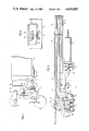
- FIG. 1 is a fragmentary side elevation of a multisection boom in accordance with the present invention in a retracted condition.
- FIG. 2 is an enlarged transverse vertical section taken on line 2--2 of FIG. 1.
- FIG. 3 is a fragmentary vertical section taken on line 3--3 of FIG. 2.
- FIG. 4 is a fragmentary vertical section taken on line 4--4 of FIG. 3.
- FIG. 5 is a horizontal section on a reduced scale taken on line 5--5 of FIG. 2.
- a multi-section telescoping boom is shown in the drawings which includes a base section 10, inner and outer mid-sections 11 and 12, and a manual fly section 13. While the invention is disclosed for convenience with this particular boom configuration, it should be understood that the invention is equally applicable to telescoping booms having a greater or lesser number of telescoping sections.
- a locking pin 14 for the manual fly section 13 is biased to an engaging position with the fly section by springs 15 held within a guide housing 16 for the locking pin depending from and forming a part of the underslung wear pad structure for the fly section at the forward end of the forward mid-section 12, FIG. 2.
- This wear pad structure includes holders 17 for lateral wear pads 18 straddling the manual fly section 13 and bottom wear pads 19 for the manual fly section.
- the biased locking pin 14 carries a guide roller 20 in rolling contact with a precision channel element 21 fixed to the bottom of fly section 13 at the center thereof.
- a receiver opening 22 for the locking pin 14 is formed through the bottom wall of the fly section so that the latter may be securely locked by the pin 14, as described in the referenced application. It can be seen that the roller 20 of the biased locking pin 14 will roll on the surface of channel element 21 during forward movement of the manual fly section 13 relative to the outer mid-section 12. The biased pin 14 will automatically engage lockingly in the opening 22 of the manual fly section when the relative movement causes the pin to register with the opening 22.
- a power retract mechanism for the pin 14 including a retract bell crank 23 pivoted at 24 to a fixed bracket extension 25 on the housing 16.
- One arm 26 of this bell crank enters a chamber 27 of the locking pin 14 and engages above a retract roller 28 held on a shaft 29 received in a transverse bore 30 of the locking pin 14.
- the other arm of bell crank 23 exteriorly of the housing 16 is in the path of movement of a rigid projecting retract member 31 or finger secured to the piston rod 32 of a relatively small hydraulic cylinder 33 fixed to the wear pad structure 34 of the boom base section 10 at the forward end of the latter.
- the cylinder 33 is illustrated as a single acting cylinder with spring return. In some cases, it can be a double acting cylinder as convenience dictates.
- the drawings illustrate the retract or actuator member 31 in a fully retracted position relative to the bell crank 23 and cylinder 33.
- An opening 35 provided in the wear pad structure 36 of boom inner mid-section 11 receives the actuator member 31 and allows the latter to bridge or reach forwardly of the boom section 11 in order to operate the bell crank 23 of locking pin 14 which, as described, is on the outer mid-section 12 of the boom.
- openings may be provided similar to the opening 35 to enable the actuator member 31 to bridge or reach forwardly of two or more boom sections in order to operate the bell crank 23 which is thus mounted on the boom section immediately surrounding fly section 13.
- the shaft 29 of roller 28 extends through a slot 37 of housing 16 and outside of the housing carries a cross pin 38 engaging in a slot 39 formed in a clevis 40 attached to the interior end of a visual indicator element or flag 41 disposed in a narrow housing 42 and pivoted between the side walls of this housing by a pivot pin 43.
- the housing side wall nearest the crane operator has a viewing opening 44 preferably shaped as an upwardly extending arrow indicative of the fact that the locking pin 14 is fully up or engaged in the opening 22 of manual fly section 13.
- At least the adjacent side face of the pivoted indicator flag 41 is painted bright orange or yellow to be easily viewable through the opening 44 when the flag is in the down position shown in FIG. 2 in response to full upward engagement of the locking pin 14 by the action of springs 15 as shown in phantom lines in the drawings.
- the biased locking pin 14 moves upwardly, it carries along the shaft 29 which in turn through the cross pin 38 and slotted clevis 40 swings the indicator flag 41 counterclockwise and downwardly on its pivot axis to expose the flag to view through the opening 44, enabling the crane operator to know with certainty that the locking pin is fully engaged.
- the indicator flag is concealed from view or substantially concealed as shown in FIG. 2.
- the interior narrow side of the housing 42 can be entirely open and the housing is profiled to fit close to one side of boom section 12 with its lower end portion disposed under wear pad structure 17 and bolted thereto as at 45.
- the clevis 40 extends outside of the housing in the open space between it and the locking pin housing 16.
- the invention provides a power retract means for the manual fly section locking pin 14 carried by the outer mid-section 12 of the boom.
- a power actuator in the form of cylinder 33 on the boom base section can reach ahead of the intervening telescoping section 11 or sections to operate a mechanical retract element for the locking pin 14 on the boom section 12 carrying the locking pin.
- the invention provides a simple visual indicator on the same side of the boom as the operator's cab directly mechanically linked to the biased locking pin 14 so that full engagement of this pin and only full engagement will place the indicator in its viewable position.
- the mechanism is simplified, very compact and positive in operation.
- the locking pin 14 does not lock the fly section 13 or other such section to the outer mid-section 12. Therefore, in the travel condition of the crane, the front of the fly section 13 is locked to the front of the outer mid-section 12 by means of a removable locking pin 46 extending through registered apertures in overlapping plates 47 and 48, respectively, of the fly section 13 and the outer mid-section 12.
- pin insertion indicator assembly of the invention is adapted for use with locking pins actuated by power means other than that shown, such as by electrical solenoids or individual hydraulic or air operated cylinders on the boom section carrying the pins or on another boom section.
- the pin insertion indicator assembly can also be used with hand operated locking pins.
- a separate pin insertion indicator housing 42 can be connected on the outer end of two or more boom sections to give the operator a visual indication of which boom sections are positively pinned together.
- two or more cylinders 33 may be arranged side-by-side beneath base section 10 and have actuator members 31 of different lengths to actuate locking pins on respectively different telescoping boom sections.
- FIG. 3 which shows a four section boom
- another locking pin 14 can be arranged in the wear pad housing 17 on the outer end of fly section 13 to lock the fifth section to the fly section when extended from the end of the fly section.
Landscapes
- Engineering & Computer Science (AREA)
- Mechanical Engineering (AREA)
- Jib Cranes (AREA)
Abstract
Description
Claims (6)
Priority Applications (2)
| Application Number | Priority Date | Filing Date | Title |
|---|---|---|---|
| US06/318,591 US4635805A (en) | 1981-11-05 | 1981-11-05 | Crane boom locking pin insertion indicator and actuator means |
| US06/861,723 US4664272A (en) | 1981-11-05 | 1986-05-12 | Telescoping crane boom with locking and indicator means |
Applications Claiming Priority (1)
| Application Number | Priority Date | Filing Date | Title |
|---|---|---|---|
| US06/318,591 US4635805A (en) | 1981-11-05 | 1981-11-05 | Crane boom locking pin insertion indicator and actuator means |
Related Child Applications (1)
| Application Number | Title | Priority Date | Filing Date |
|---|---|---|---|
| US06/861,723 Division US4664272A (en) | 1981-11-05 | 1986-05-12 | Telescoping crane boom with locking and indicator means |
Publications (1)
| Publication Number | Publication Date |
|---|---|
| US4635805A true US4635805A (en) | 1987-01-13 |
Family
ID=23238811
Family Applications (1)
| Application Number | Title | Priority Date | Filing Date |
|---|---|---|---|
| US06/318,591 Expired - Fee Related US4635805A (en) | 1981-11-05 | 1981-11-05 | Crane boom locking pin insertion indicator and actuator means |
Country Status (1)
| Country | Link |
|---|---|
| US (1) | US4635805A (en) |
Cited By (8)
| Publication number | Priority date | Publication date | Assignee | Title |
|---|---|---|---|---|
| US5060427A (en) * | 1990-02-01 | 1991-10-29 | Kidde Industries, Inc. | Extension and retraction system for four section telescopic boom having simultaneous and equal extension and retraction of the telescopic sections |
| EP0943580A3 (en) * | 1998-03-18 | 2000-07-05 | Grove U.S. LLC | Lateral jib locking device |
| US6131750A (en) * | 1997-05-28 | 2000-10-17 | Link-Belt Construction Equipment Co | Connection system for boom extension |
| US6601719B2 (en) | 2001-09-21 | 2003-08-05 | Link-Belt Construction Equipment Co., L.P., Lllp | Locking and latching system for a telescoping boom |
| US20090019794A1 (en) * | 2006-03-30 | 2009-01-22 | Oscar Centelles Vilalta | Device for collapsing towers in movable structures |
| CN101214913B (en) * | 2008-01-21 | 2010-06-02 | 长沙中联重工科技发展股份有限公司 | Connecting rod type interlocking mechanism for crane |
| US20100155633A1 (en) * | 2008-12-22 | 2010-06-24 | Pfaff Joseph L | Poppet valve operated by an electrohydraulic poppet pilot valve |
| US20240417045A1 (en) * | 2023-06-15 | 2024-12-19 | John Thomas San Giacomo, JR. | Boat lift locking apparatus |
Citations (11)
| Publication number | Priority date | Publication date | Assignee | Title |
|---|---|---|---|---|
| US2924107A (en) * | 1958-01-14 | 1960-02-09 | Mefina Sa | Control mechanism for the displacements of a machine part |
| US3346281A (en) * | 1965-01-29 | 1967-10-10 | Washington Iron Works | Lock mechanism for telescoping spar |
| US3386594A (en) * | 1967-05-08 | 1968-06-04 | Grove Mfg Company | Method of and apparatus for extending a telescopic crane boom |
| US3738075A (en) * | 1971-06-16 | 1973-06-12 | Nat Crane Corp | Extendible boom with latch means for extension and retraction |
| US3842985A (en) * | 1972-12-15 | 1974-10-22 | Harnischfeger Corp | Means for extending and retracting crane boom section |
| US3921819A (en) * | 1974-07-26 | 1975-11-25 | Kidde & Co Walter | Boom latch mechanism |
| US4053058A (en) * | 1976-05-27 | 1977-10-11 | Fmc Corporation | Suspended extensible boom |
| US4198909A (en) * | 1976-12-16 | 1980-04-22 | Faiveley S.A. | Track brake for railways |
| US4327533A (en) * | 1980-08-13 | 1982-05-04 | Kidde, Inc. | Crane boom extending, retracting and cooperative latching arrangement |
| US4352434A (en) * | 1980-05-01 | 1982-10-05 | Fmc Corporation | Pendant supported hydraulic extensible boom |
| US4433515A (en) * | 1981-11-04 | 1984-02-28 | Kidde, Inc. | Remotely operable latch and locking pin for a multi-section boom including a manual fly section |
-
1981
- 1981-11-05 US US06/318,591 patent/US4635805A/en not_active Expired - Fee Related
Patent Citations (11)
| Publication number | Priority date | Publication date | Assignee | Title |
|---|---|---|---|---|
| US2924107A (en) * | 1958-01-14 | 1960-02-09 | Mefina Sa | Control mechanism for the displacements of a machine part |
| US3346281A (en) * | 1965-01-29 | 1967-10-10 | Washington Iron Works | Lock mechanism for telescoping spar |
| US3386594A (en) * | 1967-05-08 | 1968-06-04 | Grove Mfg Company | Method of and apparatus for extending a telescopic crane boom |
| US3738075A (en) * | 1971-06-16 | 1973-06-12 | Nat Crane Corp | Extendible boom with latch means for extension and retraction |
| US3842985A (en) * | 1972-12-15 | 1974-10-22 | Harnischfeger Corp | Means for extending and retracting crane boom section |
| US3921819A (en) * | 1974-07-26 | 1975-11-25 | Kidde & Co Walter | Boom latch mechanism |
| US4053058A (en) * | 1976-05-27 | 1977-10-11 | Fmc Corporation | Suspended extensible boom |
| US4198909A (en) * | 1976-12-16 | 1980-04-22 | Faiveley S.A. | Track brake for railways |
| US4352434A (en) * | 1980-05-01 | 1982-10-05 | Fmc Corporation | Pendant supported hydraulic extensible boom |
| US4327533A (en) * | 1980-08-13 | 1982-05-04 | Kidde, Inc. | Crane boom extending, retracting and cooperative latching arrangement |
| US4433515A (en) * | 1981-11-04 | 1984-02-28 | Kidde, Inc. | Remotely operable latch and locking pin for a multi-section boom including a manual fly section |
Non-Patent Citations (2)
| Title |
|---|
| Mechanism, Linkages, and Mechanical Controls by N. P. Chironis; pp. 80 81, 10 Ways to Change Straight Line Direction , 1965. * |
| Mechanism, Linkages, and Mechanical Controls by N. P. Chironis; pp. 80-81, "10 Ways to Change Straight-Line Direction", 1965. |
Cited By (10)
| Publication number | Priority date | Publication date | Assignee | Title |
|---|---|---|---|---|
| US5060427A (en) * | 1990-02-01 | 1991-10-29 | Kidde Industries, Inc. | Extension and retraction system for four section telescopic boom having simultaneous and equal extension and retraction of the telescopic sections |
| US6131750A (en) * | 1997-05-28 | 2000-10-17 | Link-Belt Construction Equipment Co | Connection system for boom extension |
| EP0943580A3 (en) * | 1998-03-18 | 2000-07-05 | Grove U.S. LLC | Lateral jib locking device |
| US6216895B1 (en) | 1998-03-18 | 2001-04-17 | Grove U.S. L.L.C. | Lateral jib locking device |
| US6601719B2 (en) | 2001-09-21 | 2003-08-05 | Link-Belt Construction Equipment Co., L.P., Lllp | Locking and latching system for a telescoping boom |
| US20090019794A1 (en) * | 2006-03-30 | 2009-01-22 | Oscar Centelles Vilalta | Device for collapsing towers in movable structures |
| CN101214913B (en) * | 2008-01-21 | 2010-06-02 | 长沙中联重工科技发展股份有限公司 | Connecting rod type interlocking mechanism for crane |
| US20100155633A1 (en) * | 2008-12-22 | 2010-06-24 | Pfaff Joseph L | Poppet valve operated by an electrohydraulic poppet pilot valve |
| US20240417045A1 (en) * | 2023-06-15 | 2024-12-19 | John Thomas San Giacomo, JR. | Boat lift locking apparatus |
| US12545379B2 (en) * | 2023-06-15 | 2026-02-10 | John Thomas San Giacomo, JR. | Boat lift locking apparatus |
Similar Documents
| Publication | Publication Date | Title |
|---|---|---|
| US4635805A (en) | Crane boom locking pin insertion indicator and actuator means | |
| US3995761A (en) | Anti-lowering device for a boom loader | |
| US3680714A (en) | Safety device for mobile cranes | |
| US4125974A (en) | Control system for telescopic boom | |
| US2777586A (en) | Outrigger support for mobile crane or shovel | |
| US4664272A (en) | Telescoping crane boom with locking and indicator means | |
| CA1312575C (en) | Method and apparatus for extending fly section of crane boom | |
| GB1192039A (en) | Telescopic Boom Angle Control System for Cranes | |
| DE2232536C3 (en) | Overload protection for jib cranes, especially telescopic cranes | |
| US4388038A (en) | Automatic locking pin retraction mechanism | |
| US20160245917A1 (en) | Ruggedized packaging for linear distance measurement sensors | |
| US2022844A (en) | Indicator | |
| US6601719B2 (en) | Locking and latching system for a telescoping boom | |
| US3796335A (en) | Bucket position indicator | |
| US5518129A (en) | Boom including plural arms telescopically extendible and retractable successively | |
| US4235308A (en) | Locking brake for articulated vehicle | |
| US3452882A (en) | Swing mechanism for backhoes | |
| US3792780A (en) | Mechanism for positioning and restricting crane control levers to prevent dangerous load condition | |
| US1749649A (en) | Indicator for locks | |
| US4344497A (en) | Override control for axle locking apparatus of mobile crane | |
| US3166208A (en) | Hose guide arrangement | |
| CA1123387A (en) | Two way side dump bucket attachment for front end loader | |
| US3371800A (en) | Safe load control device for cranes | |
| GB1128017A (en) | Telescopic booms | |
| US3909040A (en) | Outrigger |
Legal Events
| Date | Code | Title | Description |
|---|---|---|---|
| AS | Assignment |
Owner name: KIDDE, INC. 9 BRIGHTON ROAD, CLIFTON, NJ A CORP. O Free format text: ASSIGNMENT OF ASSIGNORS INTEREST.;ASSIGNOR:MENTZER, WILLIAM R.;REEL/FRAME:003940/0422 Effective date: 19811104 |
|
| AS | Assignment |
Owner name: KIDDE INDUSTRIES, INC. Free format text: CHANGE OF NAME;ASSIGNOR:HKID 45 INC.;REEL/FRAME:005208/0907 Effective date: 19880405 Owner name: KIDDE, INC., A DE CORP. Free format text: MERGER;ASSIGNORS:KIDDE, INC., A DE CORP. (MERGED INTO);HIMP-2 INC., A DE CORP. (CHANGED TO);REEL/FRAME:005208/0890;SIGNING DATES FROM 19880402 TO 19890821 Owner name: KIDDE INDUSTRIES, INC. Free format text: CHANGE OF NAME;ASSIGNOR:BLOOM-1 INC.;REEL/FRAME:005208/0846 Effective date: 19881107 |
|
| FPAY | Fee payment |
Year of fee payment: 4 |
|
| REMI | Maintenance fee reminder mailed | ||
| LAPS | Lapse for failure to pay maintenance fees | ||
| FP | Lapsed due to failure to pay maintenance fee |
Effective date: 19950118 |
|
| STCH | Information on status: patent discontinuation |
Free format text: PATENT EXPIRED DUE TO NONPAYMENT OF MAINTENANCE FEES UNDER 37 CFR 1.362 |