US4635604A - Engine ignition timing control apparatus - Google Patents
Engine ignition timing control apparatus Download PDFInfo
- Publication number
- US4635604A US4635604A US06/704,579 US70457985A US4635604A US 4635604 A US4635604 A US 4635604A US 70457985 A US70457985 A US 70457985A US 4635604 A US4635604 A US 4635604A
- Authority
- US
- United States
- Prior art keywords
- ignition timing
- over
- engine
- change
- output
- Prior art date
- Legal status (The legal status is an assumption and is not a legal conclusion. Google has not performed a legal analysis and makes no representation as to the accuracy of the status listed.)
- Expired - Lifetime
Links
Images


Classifications
-
- F—MECHANICAL ENGINEERING; LIGHTING; HEATING; WEAPONS; BLASTING
- F02—COMBUSTION ENGINES; HOT-GAS OR COMBUSTION-PRODUCT ENGINE PLANTS
- F02P—IGNITION, OTHER THAN COMPRESSION IGNITION, FOR INTERNAL-COMBUSTION ENGINES; TESTING OF IGNITION TIMING IN COMPRESSION-IGNITION ENGINES
- F02P5/00—Advancing or retarding ignition; Control therefor
- F02P5/04—Advancing or retarding ignition; Control therefor automatically, as a function of the working conditions of the engine or vehicle or of the atmospheric conditions
- F02P5/145—Advancing or retarding ignition; Control therefor automatically, as a function of the working conditions of the engine or vehicle or of the atmospheric conditions using electrical means
- F02P5/15—Digital data processing
- F02P5/152—Digital data processing dependent on pinking
- F02P5/1527—Digital data processing dependent on pinking with means allowing burning of two or more fuels, e.g. super or normal, premium or regular
-
- Y—GENERAL TAGGING OF NEW TECHNOLOGICAL DEVELOPMENTS; GENERAL TAGGING OF CROSS-SECTIONAL TECHNOLOGIES SPANNING OVER SEVERAL SECTIONS OF THE IPC; TECHNICAL SUBJECTS COVERED BY FORMER USPC CROSS-REFERENCE ART COLLECTIONS [XRACs] AND DIGESTS
- Y02—TECHNOLOGIES OR APPLICATIONS FOR MITIGATION OR ADAPTATION AGAINST CLIMATE CHANGE
- Y02T—CLIMATE CHANGE MITIGATION TECHNOLOGIES RELATED TO TRANSPORTATION
- Y02T10/00—Road transport of goods or passengers
- Y02T10/10—Internal combustion engine [ICE] based vehicles
- Y02T10/40—Engine management systems
Definitions
- This invention relates to an ignition timing control apparatus for an internal combustion engine, and in particular to an ignition timing control apparatus for an internal combustion engine which is operable either with a low-octane rating fuel or a high-octane rating fuel, or with a mixture thereof.
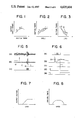
- FIG. 1 shows an ignition timing vs output shaft torque characteristic in an internal combustion engine in the case where a commercially available low-octane gasoline (regular gasoline) and a commercially available high octane gasoline (premium gasoline) of which the octane rating is higher than that of low-octane gasoline.
- point A indicates a knock limit for low-octane gasoline
- point B indicates a knock limit for high-octane gasoline
- point C indicates a Minimum advance for Best Torque (MBT), in which knock arises when the angle of the ignition timing is advanced beyond these points.
- MBT Minimum advance for Best Torque
- FIGS. 2 and 3 show ignition timing characteristics of points A, B, and C in FIG. 1 respectively represented as a function of a revolutional speed of an internal combustion engine (FIG. 2) and a function of a load of the engine (FIG. 3).
- the reference ignition timing characteristic is preset only for a predetermined octane rating gasoline, e.g. the low-octane rating regular gasoline. Therefore when the gasoline of the engine is changed over from the low octane rating gasoline to the high octane rating gasoline or when both of the gasolines are mixed in use, an increase in the output of the engine can not be expected without any change or modification thereof, so that the presetting of the reference ignition timing must be repeated towards an advance angle, by some method.
- a predetermined octane rating gasoline e.g. the low-octane rating regular gasoline. Therefore when the gasoline of the engine is changed over from the low octane rating gasoline to the high octane rating gasoline or when both of the gasolines are mixed in use, an increase in the output of the engine can not be expected without any change or modification thereof, so that the presetting of the reference ignition timing must be repeated towards an advance angle, by some method.
- an advance angle characteristic different from that of the regular gasoline is required to be set as the ignition timing because of the difference in the advance angle characteristic between the knock limits A, B and the MBT point C as shown in FIGS. 2 and 3.
- the reference ignition timing characteristic be preset to point B in FIG. 1 for premium gasoline and that when using the regular gasoline, the ignition timing be retarded to point A in FIG. 1 by means of the above knock control technique.
- the broad ignition timing interval for a knock control between points A and B in FIG. 1 when knocks arise during an acceleration operation etc., of the engine, intensive knocks disadvantageously arise during the retarding shift of the ignition timing from point B to point A in FIG. 1.
- Japanese Patent Application Laid-open No. 58-57072 published on Apr. 5, 1983, titled "Method for Controlling Ignition Timing of Electronic Controlled Engine” discloses a change-over the ignition timing of the engine depending on the octane rating of a fuel.
- an ignition timing control apparatus for an internal combustion engine comprises: a sensing means for sensing vibrations including knocks in the engine; knock signal deriving means for deriving knock signals from the output of the sensing means; an ignition timing change-over determining means for determining from knock signals derived by the knock signal deriving means whether or not the change-over of the reference ignition timing is necessary from the knock condition associated with a fuel used for said engine; a change-over magnitude determining means for correcting the change-over magnitude of the reference ignition timing according to the operating condition of said engine and the output of said ignition timing change-over determining means; and, an ignition timing change-over means for changing over the reference ignition timing according to the output of said change-over magnitude determining means.
- an ignition timing control apparatus for an internal combustion engine comprises: a sensing means for sensing vibrations including knocks in the engine; knock signal deriving means for deriving knock signals from the output of said sensing means, for deriving said knock signals; a displacement magnitude determining means for determining from the output of the knock signal deriving means a displacement magnitude for the reference ignition timing of the engine; an ignition timing displacement means for displacing the reference ignition timing by the displacement magnitude according to the output of the displacement magnitude determining means; and, a correction means for correcting the displacement magnitude for the reference ignition timing according to the operating condition of the engine.
- FIG. 1 shows an output shaft torque characteristic of an internal combustion engine as a function of ignition timing
- FIG. 2 shows a characteristic curve of ignition timing in relation to the rotational speed of an engine
- FIG. 3 shows a characteristic curve of ignition timing in relation to a load on an engine
- FIG. 4 shows a block diagram of a first embodiment of an ignition timing control apparatus for an internal combustion engine in accordance with this invention
- FIGS. 5(a)-5(c) shows waveform graphs for explaining the operation of the knock signal deriving portion in FIG. 4;
- FIGS. 6(a)-6(e) shows waveform graphs for explaining the operations of the various portions of the control apparatus used in FIG. 4;
- FIGS. 7 and 8 respectively show the output voltage characteristics of a function generator used in FIG. 4 in relation to the load on the engine and the engine speed;
- FIG. 9 shows a block diagram of a second embodiment of an ignition timing control apparatus for an internal combustion engine in accordance with this invention.
- FIGS. 10(a)-10(f) shows waveform graphs for explaining the operations of the various portions of the control apparatus used in FIG. 9;
- FIG. 11 shows a block diagram of the arrangement of the operating region determining portion used in FIG. 9.
- FIG. 12 shows a map of an operating region of the engine defined by the load and speed on the engine, used in the second embodiment of this invention.
- FIG. 4 shows a first embodiment of this invention, where a knock sensor 1 is mounted on an internal combustion engine (not shown) to sense knocks in the engine.
- the output signal of the knock sensor 1 is received as an input by a knock signal deriving portion 2, enclosed with dotted lines, which is composed of a bandpass filter 21, a noise level detector 22, and a first comparator 23.
- the input of the bandpass filter 21 is connected to the knock sensor 1 and the output thereof is connected to the noise level detector 22 and one input of the first comparator 23.
- the output of the noise level detector 22 is connected to the other input of the first comparator 23.
- the knock signal deriving portion 2 is connected to a retard controlling voltage generator 31.
- This retard controlling voltage generator 31 is connected to a second comparator 32 which in turn is connected to a flip-flop 33.
- the flip-flop 33 is reset by a reset circuit 34. It is to be noted that the retard controlling voltage generator 31, the comparator 32, the flip-flop 33, and the reset circuit 34 together form an ignition timing change-over determining portion 3.
- the second comparator 32 compares the output voltage of the retard controlling voltage generator 31 with a predetermined voltage level Vth to provide as an output therefrom a compared result to the set input of the flip-flop 33.
- the output of the flip-flop 33 in the ignition timing change-over determining portion 3 is connected to one input of an analog switch 41 the other input of which is connected to the output of a function generator 42.
- the analog switch 41 and the function generator 42 together form an ignition timing change-over magnitude determining portion 4 which is connected to the output of an operating condition sensing means, herein shown in part as a pressure sensor 9, for detecting an inlet air pressure of the engine and to the output of a frequency-voltage converter 10.
- the outputs of the retard controlling voltage generator 31 and the analog switch 41 are both connected to a retard controlling input of an ignition timing phase-shifter 5 for phase-shifting or retarding a reference ignition timing preset in a reference ignition timing signal generator 6 in accordance with the output voltage of the retard controlling voltage generator 31 and the output voltage of the function generator 42 through the analog switch 41 and provides as an output therefrom an ignition signal indicative of the retarded ignition timing to an ignition circuit 7 which causes an ignition coil 8 to develop thereacross a high voltage necessary for the ignition of the engine.
- a frequency-voltage (F/V) converter 10 receives as an input an ignition signal provided as an output from the phase-shifter 5 and converts the frequency of the same into a voltage, thereby providing as an output therefrom a voltage corresponding to the revolution of the engine.
- FIGS. 5 and 6 showing waveforms indicating the operation of each of the circuits.
- the knock sensor 1 is a vibration acceleration sensor generally well known as being mounted on the cylinder block (not shown) etc., of an engine, which converts the mechanical vibration into an electrical signal, and generates a vibration wave signal, as shown in FIG. 5(a), which is received by the bandpass filter 21.
- the bandpass filter 21 only passes therethrough a frequency component inherent in knocks, from the output signal of the knock sensor 1, thereby suppressing a noise component not relating to knocks to provide as an output a signal having a good S/N ratio as shown in FIG. 5(b) by wave-form A.
- the noise level detector 22 may be composed of, e.g. a half-wave rectifying circuit, an averaging circuit, and an amplifying circuit etc.
- the noise level detector 22 converts the output of the bandpass filter 21 (FIG. 5(b), wave-form A) into a DC voltage by the half-wave rectification and the averaging operations, the DC voltage being amplified with a predetermined amplification to have a level, as shown in FIG. 5(b) by a wave-form B, higher than the noise component of the output signal of the bandpass filter 21 (FIG. 5(b), wave-form A) but lower than the knock component of the same.
- the comparator 23 compares the output signal of the noise level detector 22 (FIG. 5(b), wave-form B) with the output of the bandpass filter 21 (FIG. 5(b), wave-form A). In the case where no knock occurs (FIG. 5, section C), since the output signal of the bandpass filter 21 (FIG. 5(b), wave-form A) is not greater than the output signal of the noise level detector 22 (FIG. 5(b), wave-form B), the comparator 23 provides no output, while in the case where knocks occur (FIG. 5, section D), since the former signal is greater than the latter signal, the comparator 23 provides as an output therefrom a pulse train as shown in FIG. 5(c). Accordingly, the output pulse train from the comparator 23 can be used for determining whether or not knocks have occurred.
- FIG. 6 shows waveforms indicating the operation of the ignition timing change-over determining portion 3 which includes the retard controlling voltage generator 31, the comparator 32, and the flip-flop 33.
- the retard controlling voltage generator 31 may be composed of e.g. an integration circuit which, when the first comparator 23 provides as an output therefrom a pulse train as shown in FIG. 6(a), integrates the pulse train to raise the output voltage as shown in FIG. 6(b).
- the first comparator 23 provides no output pulse train, indicating the absence of knocks, the output of the voltage generator 31 gradually falls at a predetermined rate.
- the voltage generator 31 generates a retard controlling voltage for retarding the ignition timing up to the knock limit point on a real time basis, whereby the ignition timing phase-shifter 5 receives as an input the retard controlling voltage to retard the angle of the ignition timing, thereby suppressing the occurrence of knocks.
- the output level of the second comparator 32 is inverted from a low level to a high level as shown in FIG. 6(c) when the retard controlling voltage from the voltage generator 31 exceeds the predetermined threshold level Vth.
- This threshold level Vth is predetermined such that in the case where the reference ignition timing is preset for that of premium gasoline, the retard controlling voltage does not go above Vth when premium gasoline is used while it does not go below Vth when regular gasoline is used.
- the flip-flop 33 is set to provide a high logic level output when the output of the comparator 32 is at the high level and reset to provide a low logic level output when the output of the reset circuit 34 is at a high level.
- the reset circuit 34 provides as an output therefrom a high level pulse, e.g. at the starting time of the engine, as shown in FIG. 6(d).
- the output state of the flip-flop 33 is shown in FIG. 6(e).
- the flip-flop 33 is reset by the reset circuit 34 to provide a low level output signal as above described.
- This signal indicates a "premium gasoline mode” in which the ignition timing of the engine is not changed over.
- the output of the comparator 32 becomes the high level as shown in FIG. 6(c)
- the output of the flip-flop 33 is changed over to the high level, which indicates a "regular gasoline mode” in which the ignition timing of the engine is changed over. Thereafter, the regular gasoline mode is retained until the engine is stopped. It is needless to say that if the output of the comparator 32 does not become high after the starting of the engine, the output of the flip-flop 33 remains at the low level and the engine operates at the premium gasoline mode.
- the ignition timing change-over determining portion 3 determines, from the output voltage of the retard controlling voltage generator 31, which gasoline (premium or regular) is used for the engine.
- the ignition timing change-over magnitude determining portion 4 determines an ignition timing change-over magnitude from an operating condition of the engine, and provides as an output therefrom a voltage for the change-over of the ignition timing to the phase-shifter 5 according to the determined result of the change-over determining portion 3.
- the function generator 42 generates voltages corresponding to respective predetermined functions which are respectively illustrated in FIGS. 2 and 3 in relation to the load on the engine as shown in FIG. 7 and the speed of the engine as shown in FIG. 8 in response to the output voltages of the pressure sensor 9 and the F/V converter 10, respectively, and provides as an output therefrom the multiplied value of both of the voltages.
- the analog switch 41 When the output of flip-flop 33 is at the high level (regular gasoline mode), the analog switch 41 is rendered to be in an ON mode whereby the output voltage of the function generator 42 is provided as an input to the ignition timing phase-shifter 5. On the otherhand, when the output of the flip-flop 33 is at the low level (premium gasoline mode), the analog switch 41 is rendered to be in an OFF mode whereby the output of the pressure sensor 9 is not inputted to the phase-shifter 5.
- the phase-shifter 5 then phase-shifts the reference ignition timing signal from the reference ignition timing signal generator 6 in the retarding direction according to the output voltages of the function generator 42 which are passed through the analog switch 41 and of the retard controlling voltage generator 31, and provides as an output therefrom an ignition signal of an optimum ignition timing characteristic corresponding to the kind of gasoline being used.
- This phase-shifter 5 is generally well known in the art of ignition timing control apparatus so that the description thereof is omitted.
- the reference ignition timing signal generator 6 provides as an output therefrom the reference ignition timing signal set by the operating condition of the engine such as the speed and the load of the engine.
- This reference ignition timing characteristic may be determined by, e.g., the operating characteristics of the centrifugal governer of a distributor and a pressure diaphragm, or may be stored in a memory of an electronic advance controlling device.
- a reset pulse may be generated by the detection of the fact that additional gasoline is being poured into the gasoline tank through the detection of the opening/closing operation of the fuel cap of a gasoline tank upon supplying the gasoline or through the detection of a change in a fuel gauge setting.
- a backup power source may be added so that the output mode of the flip-flop 33 is memorized even during the stop of the engine.
- the reference ignition timing preset in the generator 6 may be preset for either one of premium or regular gasoline in which the threshold level of the comparator 32 is required to be varied accordingly.
- FIG. 9 A second embodiment of an ignition timing control apparatus for an internal combustion engine using mixed gasoline is shown in FIG. 9. As mentioned above, this second embodiment also serves to shorten the change-over ignition timing interval for the knock control between points A and B in FIG. 1, thereby enhancing the responsiveness of the knock control. In addition to this, this embodiment can perform a failsafe function to preclude an erroneous change-over control.
- the knock deriving portion 2 is connected to an ignition timing displacement determining portion 3' which is composed of a retard controlling voltage generator 31, a second comparator 32, a third comparator 32', first and second AND gate 35 and 35', an integrator 36, and a multiplier 37.
- the input of the retard controlling voltage generator 31 is connected to the output of the first comparator 23.
- the comparators 32 and 32' compare the output voltage of the retard control voltage generator 31 respectively with first and second predetermined threshold levels Vth and Vth', the compared results respectively being connected to respective one input of the AND gates 35 and 35'.
- the respective other input of the AND gate 35 and 35' is commonly connected to the output of an operating region determining portion 45.
- the integrator 36 has two inputs of which an advancing input is connected to the output of the AND gate 35 and a retarding input connected to the output of the AND gate 35'.
- the multiplier 37 receives as inputs the output voltage of the integrator 36 and the output voltage of the function generator 42 which has been described in the first embodiment.
- the operating region determining portion 45 and the function generator 42 together receive as inputs the output voltages of the pressure sensor 9 and the F/V converter 10 as above described.
- ignition timing phase-shifter 5' phase-shifts the reference ignition timing signal provided as an output from the reference ignition timing signal generator 6 in accordance with the output voltages of the retard controlling voltage generator 31 and the multiplier 37, and provides as an output therefrom an ignition signal indicative of the phase-shifted, i.e., displaced ignition timing to the ignition cicuit 7 which causes the ignition coil 8 to develop thereacross a high voltage necessary for the ignition of the engine.
- the second comparator 32 and the third comparator 32' compare the retard controlling voltage from the signal generator 31 with the threshold levels Vth and Vth' respectively.
- the voltage relationship between Vth and Vth' is set such that Vmin ⁇ Vth ⁇ Vth' ⁇ Vmax for e.g. the maximum value (Vmax) and the minimum value (Vmin) of the retard controlling voltage.
- the second comparator 32 provides as an output therefrom a high level signal as shown in FIG. 10(c) when the retard controlling voltage from the generator 31 is lower than the first predetermined threshold voltage Vth which is inputed to the comparator 32 for the comparison.
- the third comparator 32' provides as an output therefrom a high level signal as shown in FIG. 10(d) when the retard controlling voltage from the generator 31 is higher than the second predetermined threshold voltage Vth' which is inputed to the comparator 32' for the comparison.
- the integrator 36 gradually decreases its output voltage as shown in FIG. 10(f) when the high level output signal of the comparator 32 is provided to the advancing input of the integrator 36 through the AND gate 35, thereby displacing it in the advancing direction.
- the integrator 36 gradually increases its output voltage as shown in FIG. 10(f) when the high level output signal of the comparator 32' is provided to the retarding input of the integrator 36 through the AND gate 35', thereby displacing it in the retarding direction. If the advancing and retarding inputs of the integrator 36 are both at the low level, the output voltage of the integrator 36 is held as it is.
- the operating region determining portion 45 is provided.
- the operating region determining portion 45 receives as inputs an operating load information of the engine from the pressure sensor 9 and an operating speed information of the engine through a frequency-voltage conversion of the ignition signal from the ignition timing phase-shifter 5' to form a data map for the operating region based on the load and speed of the engine. Furthermore, an operating region where the output voltage of the integrator 36 may be displaced in the advancing or retarding direction is preset so that it provides as an output therefrom a high level signal as shown in FIG. 10(e) when the operating condition lies in the preset region while otherwise it provides as an output therefrom a low level signal.
- FIG. 11 there is shown a block diagram of the arrangement of the operating region determining portion 45 which is composed of a fourth comparator 451, a fifth comparator 452, a sixth comparator 453, a seventh comparator 454, and an AND gate 455.
- the common input of the comparators 451 and 452 is connected to the output of the ignition timing phase-shifter 5' through the F/V converter 10 to provide as an output therefrom a voltage proportional to the engine speed.
- the comparator 451 has two threshold levels V1 and V2 to be compared with the output voltage of the F/V converter 10.
- the comparator 452 also has two threshold levels V1' and V2' to be compared with the output voltage of the F/V converter 10.
- the comparator 451 when the output voltage of the F/V converter 10 is present between V1 and V2, the comparator 451 provides as an output therefrom a high level signal while otherwise it provides as an output therefrom a low level signal, and when the output voltage of the F/V converter 10 is present between V1' and V2', the comparator 452 provides as an output therefrom a high level signal while otherwise it provides as an output therefrom a low level signal.
- the input of the comparator 453 is connected to the output of the pressure sensor 9 to receive as an input a voltage proportional to the inlet air pressure of the engine, that is the load information of the engine.
- the comparator 453 also has two threshold levels V3 and V4 to be compared with the output voltage of the pressure sensor 9.
- the input of the comparator 454 is also connected to the output of the pressure sensor 9 to receive as an input a voltage proportional to the inlet air pressure of the engine, that is the load information of the engine.
- the comparator 454 also has two threshold levels V3' and V4' to be compared with the output voltage of the pressure sensor 9.
- the comparator 453 when the output voltage of the pressure sensor 9 is present between V3 and V4, the comparator 453 provides as an output therefrom a high level signal while otherwise it provides as an output therefrom a low level signal, and when the output voltage of the pressure sensor 9 is present between V3' and V4', the comparator 454 provides as an output therefrom a high level signal while otherwise it provides as an output therefrom a low level signal.
- the AND gate 455 whose inputs are connected to the respective outputs of the comparators 451-454 performs the logical multiplication of the outputs of the comparators 452-455.
- FIG. 12 shows an operating region of the engine represented by the output voltage of the F/V converter 451 (speed information) and the output voltage of the pressure sensor 9 (load information).
- the hatched portion X designates an operating region defined by a predetermined speed region of V1-V2 as well as a predetermined load region of V3-V4 with the combination of the comparators 451 and 453 while the hatched portion Y designates an operating region defined by a predetermined speed region of V1'-V2' as well as a predetermined load region of V3'-V4' with the combination of the comparators 452 and 454.
- the operating region determining portion 45 provide as an output therefrom a high level signal through the AND gate 455, as shown in FIG. 10(e).
- the AND gates 35 and 35' control the passing of the output signals of the comparators 32 and 32' to the integrator 36 by means of the output signal of the operating region determining portion 45.
- the integrator 36 displaces its output voltage in the advancing direction while when the retard controlling voltage is larger than Vth' and when the operating condition of the engine lies in the predetermined superposed map region defined in FIG. 12, the integrator 36 displaces its output voltage in the retarding direction.
- the integrator 36 holds its output voltage as it is.
- the multiplier 37 then multiplies the output voltage of the integrator 36 and the output voltage of the function generator 42. This means that the output voltage of the integrator 36 is weighed by the output voltage of the function generator 42.
- the ignition timing phase-shifter 5' then displaces the phase angle of the reference ignition timing signal set in the reference ignition timing signal generator 6 whereby the most efficiently operate ignition timing for the engine is obtained.
- knocks are detected by a knock sensor, whether or not displacement of the reference ignition timing in the advancing or retarding direction is required is determined from the detected occurrence of knocks, and the reference ignition timing is displaced in angle according to an ignition timing displacement magnitude weighed by the operating condition of the engine, whereby the most efficiently operable ignition timing for the engine is advantageously obtained.
Landscapes
- Engineering & Computer Science (AREA)
- Signal Processing (AREA)
- Chemical & Material Sciences (AREA)
- Combustion & Propulsion (AREA)
- Mechanical Engineering (AREA)
- General Engineering & Computer Science (AREA)
- Electrical Control Of Ignition Timing (AREA)
Abstract
Description
Claims (19)
Applications Claiming Priority (4)
| Application Number | Priority Date | Filing Date | Title |
|---|---|---|---|
| JP59034574A JPS60178974A (en) | 1984-02-24 | 1984-02-24 | Ignition timing controller for internal-combustion engine |
| JP59-34574 | 1984-02-24 | ||
| JP59-34573 | 1984-02-24 | ||
| JP3457384A JPS60178973A (en) | 1984-02-24 | 1984-02-24 | Ignition timing controller for internal-combustion engine |
Publications (1)
| Publication Number | Publication Date |
|---|---|
| US4635604A true US4635604A (en) | 1987-01-13 |
Family
ID=26373402
Family Applications (1)
| Application Number | Title | Priority Date | Filing Date |
|---|---|---|---|
| US06/704,579 Expired - Lifetime US4635604A (en) | 1984-02-24 | 1985-02-22 | Engine ignition timing control apparatus |
Country Status (1)
| Country | Link |
|---|---|
| US (1) | US4635604A (en) |
Cited By (4)
| Publication number | Priority date | Publication date | Assignee | Title |
|---|---|---|---|---|
| EP0302735A3 (en) * | 1987-08-05 | 1989-06-28 | Mitsubishi Jidosha Kogyo Kabushiki Kaisha | Control apparatus of an internal combustion engine |
| GB2231917A (en) * | 1989-05-18 | 1990-11-28 | Fuji Heavy Ind Ltd | Ignition timing control system |
| USRE34316E (en) * | 1988-03-10 | 1993-07-20 | Hitachi, Ltd. | Ignition timing control apparatus for an internal combustion engine |
| DE10338664A1 (en) * | 2003-08-22 | 2005-03-24 | Audi Ag | Motor vehicle petrol engine operating method in which fuel quality measurements made using the knocking regulation system are used in a cold start to optimize the fuel-air mixture taking into account fuel quality |
Citations (12)
| Publication number | Priority date | Publication date | Assignee | Title |
|---|---|---|---|---|
| US3718126A (en) * | 1969-07-21 | 1973-02-27 | Toyota Motor Co Ltd | Ignition timing regulating device for internal combustion engines |
| US3822583A (en) * | 1972-11-30 | 1974-07-09 | Standard Oil Co | Method for determining octane ratings of fuels under road conditions |
| JPS5772A (en) * | 1980-05-29 | 1982-01-05 | Fuji Electric Co Ltd | Switching regulator |
| US4344400A (en) * | 1979-07-31 | 1982-08-17 | Nissan Motor Co., Ltd. | Control device for an internal combustion engine |
| US4351281A (en) * | 1979-07-27 | 1982-09-28 | Volkswagenwerk Aktiengesellschaft | Method and system for operation of a spark-ignited internal combustion engine |
| JPS5827886A (en) * | 1981-08-12 | 1983-02-18 | Toyota Motor Corp | Method of controlling knocking for internal combustion engine |
| JPS58143169A (en) * | 1982-02-17 | 1983-08-25 | Toyota Motor Corp | Method for controlling ignition timing |
| US4440129A (en) * | 1979-05-05 | 1984-04-03 | Mitsubishi Denki Kabushiki Kaisha | Ignition timing control system for internal combustion engine |
| US4444172A (en) * | 1981-07-18 | 1984-04-24 | Robert Bosch Gmbh | Internal combustion engine knock sensing system |
| US4448163A (en) * | 1980-12-11 | 1984-05-15 | Nissan Motor Company, Limited | Ignition timing control device for internal combustion engines |
| US4463565A (en) * | 1981-02-19 | 1984-08-07 | Ab Volvo | Turbocharged internal combustion engine with boost pressure and ignition timing control for preventing knocking combustion |
| US4509331A (en) * | 1981-10-27 | 1985-04-09 | Nissan Motor Company, Limited | Knock-free engine control system for turbocharged automotive engine |
-
1985
- 1985-02-22 US US06/704,579 patent/US4635604A/en not_active Expired - Lifetime
Patent Citations (12)
| Publication number | Priority date | Publication date | Assignee | Title |
|---|---|---|---|---|
| US3718126A (en) * | 1969-07-21 | 1973-02-27 | Toyota Motor Co Ltd | Ignition timing regulating device for internal combustion engines |
| US3822583A (en) * | 1972-11-30 | 1974-07-09 | Standard Oil Co | Method for determining octane ratings of fuels under road conditions |
| US4440129A (en) * | 1979-05-05 | 1984-04-03 | Mitsubishi Denki Kabushiki Kaisha | Ignition timing control system for internal combustion engine |
| US4351281A (en) * | 1979-07-27 | 1982-09-28 | Volkswagenwerk Aktiengesellschaft | Method and system for operation of a spark-ignited internal combustion engine |
| US4344400A (en) * | 1979-07-31 | 1982-08-17 | Nissan Motor Co., Ltd. | Control device for an internal combustion engine |
| JPS5772A (en) * | 1980-05-29 | 1982-01-05 | Fuji Electric Co Ltd | Switching regulator |
| US4448163A (en) * | 1980-12-11 | 1984-05-15 | Nissan Motor Company, Limited | Ignition timing control device for internal combustion engines |
| US4463565A (en) * | 1981-02-19 | 1984-08-07 | Ab Volvo | Turbocharged internal combustion engine with boost pressure and ignition timing control for preventing knocking combustion |
| US4444172A (en) * | 1981-07-18 | 1984-04-24 | Robert Bosch Gmbh | Internal combustion engine knock sensing system |
| JPS5827886A (en) * | 1981-08-12 | 1983-02-18 | Toyota Motor Corp | Method of controlling knocking for internal combustion engine |
| US4509331A (en) * | 1981-10-27 | 1985-04-09 | Nissan Motor Company, Limited | Knock-free engine control system for turbocharged automotive engine |
| JPS58143169A (en) * | 1982-02-17 | 1983-08-25 | Toyota Motor Corp | Method for controlling ignition timing |
Cited By (6)
| Publication number | Priority date | Publication date | Assignee | Title |
|---|---|---|---|---|
| EP0302735A3 (en) * | 1987-08-05 | 1989-06-28 | Mitsubishi Jidosha Kogyo Kabushiki Kaisha | Control apparatus of an internal combustion engine |
| US4913117A (en) * | 1987-08-05 | 1990-04-03 | Mitsubishi Jidosha Kogyo Kabushiki Kaisha | Control apparatus of an internal combustion engine |
| USRE34316E (en) * | 1988-03-10 | 1993-07-20 | Hitachi, Ltd. | Ignition timing control apparatus for an internal combustion engine |
| GB2231917A (en) * | 1989-05-18 | 1990-11-28 | Fuji Heavy Ind Ltd | Ignition timing control system |
| GB2231917B (en) * | 1989-05-18 | 1993-10-27 | Fuji Heavy Ind Ltd | A method and a system for controlling ignition timing of an internal combustion engine |
| DE10338664A1 (en) * | 2003-08-22 | 2005-03-24 | Audi Ag | Motor vehicle petrol engine operating method in which fuel quality measurements made using the knocking regulation system are used in a cold start to optimize the fuel-air mixture taking into account fuel quality |
Similar Documents
| Publication | Publication Date | Title |
|---|---|---|
| JP2505243B2 (en) | Electronic ignition timing controller | |
| US4508079A (en) | Knocking control system for internal combustion engine | |
| US4684896A (en) | Testing method for ignition systems of internal combustion engines in motor vehicles | |
| US4370962A (en) | System for producing a pulse signal for controlling an internal combustion engine | |
| US4236491A (en) | Ignition timing control apparatus for internal combustion engines | |
| US4112351A (en) | Dual threshold low coil signal conditioner | |
| US4649888A (en) | Ignition control apparatus for internal combustion engines | |
| KR940001938B1 (en) | Knocking control device for internal combustion engine | |
| US4399802A (en) | Ignition energy control method and system | |
| US4676212A (en) | Ignition timing control apparatus for an internal combustion engine having a plurality of cylinders | |
| US4586474A (en) | Knock suppression apparatus for internal combustion engine | |
| US5190011A (en) | Knocking control method and apparatus for internal combustion engine | |
| US4715342A (en) | System for controlling the ignition timing of an internal combustion engine | |
| US4612900A (en) | Engine operating parameter control apparatus | |
| US4377785A (en) | Device for diagnosing ignition system for use in internal combustion engine | |
| US4635604A (en) | Engine ignition timing control apparatus | |
| US4612901A (en) | Engine ignition timing control apparatus | |
| US4385607A (en) | Automobile ignition timing control system | |
| KR940004351B1 (en) | Knock detector | |
| JPS61237884A (en) | Knocking controller for internal-combustion engine | |
| US4610232A (en) | Ignition timing control apparatus for internal combustion engine | |
| US4374510A (en) | Ignition timing correcting system for internal combustion engine | |
| US4384561A (en) | Ignition timing correcting system for internal combustion engine | |
| JPH0258470B2 (en) | ||
| KR890000469B1 (en) | Ignition timing control apparatus for internal combustion engine |
Legal Events
| Date | Code | Title | Description |
|---|---|---|---|
| AS | Assignment |
Owner name: MITSUBISHI DENKI KABUSHIKI KAISHA, 2-3, MARUNOUCHI Free format text: ASSIGNMENT OF ASSIGNORS INTEREST.;ASSIGNORS:IWATA, TOSHIO;KOMURASAKI, SATOSHI;UEDA, ATSUSHI;REEL/FRAME:004374/0220 Effective date: 19850208 |
|
| STCF | Information on status: patent grant |
Free format text: PATENTED CASE |
|
| FEPP | Fee payment procedure |
Free format text: PAYOR NUMBER ASSIGNED (ORIGINAL EVENT CODE: ASPN); ENTITY STATUS OF PATENT OWNER: LARGE ENTITY |
|
| FPAY | Fee payment |
Year of fee payment: 4 |
|
| AS | Assignment |
Owner name: SUNDSTRAND CORPORATION A DE CORPORATION Free format text: ASSIGNMENT OF ASSIGNORS INTEREST.;ASSIGNOR:SUNDSTRAND DATA CONTROL, INC., A CORPORATION OF DE;REEL/FRAME:005994/0074 Effective date: 19920113 Owner name: SUNDSTRAND CORPORATION, STATELESS Free format text: ASSIGNMENT OF ASSIGNORS INTEREST;ASSIGNOR:SUNDSTRAND DATA CONTROL, INC., A CORPORATION OF DE;REEL/FRAME:005994/0074 Effective date: 19920113 |
|
| FEPP | Fee payment procedure |
Free format text: PAYER NUMBER DE-ASSIGNED (ORIGINAL EVENT CODE: RMPN); ENTITY STATUS OF PATENT OWNER: LARGE ENTITY Free format text: PAYOR NUMBER ASSIGNED (ORIGINAL EVENT CODE: ASPN); ENTITY STATUS OF PATENT OWNER: LARGE ENTITY |
|
| FPAY | Fee payment |
Year of fee payment: 8 |
|
| FPAY | Fee payment |
Year of fee payment: 12 |