US4635376A - Angle measuring apparatus - Google Patents
Angle measuring apparatus Download PDFInfo
- Publication number
- US4635376A US4635376A US06/693,942 US69394285A US4635376A US 4635376 A US4635376 A US 4635376A US 69394285 A US69394285 A US 69394285A US 4635376 A US4635376 A US 4635376A
- Authority
- US
- United States
- Prior art keywords
- angle
- support
- detecting device
- level detecting
- horizontal level
- Prior art date
- Legal status (The legal status is an assumption and is not a legal conclusion. Google has not performed a legal analysis and makes no representation as to the accuracy of the status listed.)
- Expired - Fee Related
Links
Images


Classifications
-
- G—PHYSICS
- G01—MEASURING; TESTING
- G01B—MEASURING LENGTH, THICKNESS OR SIMILAR LINEAR DIMENSIONS; MEASURING ANGLES; MEASURING AREAS; MEASURING IRREGULARITIES OF SURFACES OR CONTOURS
- G01B5/00—Measuring arrangements characterised by the use of mechanical techniques
- G01B5/24—Measuring arrangements characterised by the use of mechanical techniques for measuring angles or tapers; for testing the alignment of axes
- G01B5/242—Sine bars; Sine plates
-
- G—PHYSICS
- G01—MEASURING; TESTING
- G01B—MEASURING LENGTH, THICKNESS OR SIMILAR LINEAR DIMENSIONS; MEASURING ANGLES; MEASURING AREAS; MEASURING IRREGULARITIES OF SURFACES OR CONTOURS
- G01B3/00—Measuring instruments characterised by the use of mechanical techniques
- G01B3/56—Gauges for measuring angles or tapers, e.g. conical calipers
-
- Y—GENERAL TAGGING OF NEW TECHNOLOGICAL DEVELOPMENTS; GENERAL TAGGING OF CROSS-SECTIONAL TECHNOLOGIES SPANNING OVER SEVERAL SECTIONS OF THE IPC; TECHNICAL SUBJECTS COVERED BY FORMER USPC CROSS-REFERENCE ART COLLECTIONS [XRACs] AND DIGESTS
- Y10—TECHNICAL SUBJECTS COVERED BY FORMER USPC
- Y10S—TECHNICAL SUBJECTS COVERED BY FORMER USPC CROSS-REFERENCE ART COLLECTIONS [XRACs] AND DIGESTS
- Y10S33/00—Geometrical instruments
- Y10S33/01—Magnetic
Definitions
- the invention relates to angle measuring apparatus for determining the angle a planar surface makes with a cylindrical surface.
- ink is transferred from a reservoir to an engraved cylinder and it is necessary to remove excess ink before contact is made between the ink carrying surface of the cylinder and a record medium.
- it is conventional to mount a doctor blade adjacent to the cylinder to removed excess ink and to maintain a constant ink thickness. It has been found that the angle of inclination of the doctor blade to the cylinder critically determines the performance of the printing process and also affects the lifetime of the cylinder. It is therefore desirable to determine this angle.
- More accurate, known angle measuring apparatus comprises an elongate support; a horizontal level detecting device pivotally connected to an upper surface of the support; and means for determining the angle between the support and the horizontal level detecting device.
- Such apparatus is hereinafter referred to as of the kind described.
- One example of apparatus of the kind described is the well known clinometer. This is not suitable for determining the inclination angle of a doctor blade to a gravure cylinder in view of the curved form of the cylinder.
- angle measuring apparatus of the kind described which is characterised in that an under surface of the support includes a pair of spaced projecting feet, the arrangement being such that when the apparatus is placed on a cylinder, the upper surface of the support is substantially parallel with a chord of the cylinder.
- the provision of a pair of spaced projecting feet enables the angle measuring apparatus to be accurately located at the junction between the doctor blade and the cylinder and spaces the upper surface of the support a sufficient distance from the cylinder so that the upper surface is substantially parallel with a chord of the cylinder.
- the support comprises two separable sections, one section providing the upper surface of the support and the other section including the projecting feet.
- two sections may be connected in any convenient way but preferably at least one section includes a portion of magnetisable material while the other includes a magnet.
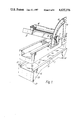
- FIG. 1 is a perspective view of the apparatus
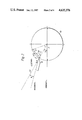
- FIG. 2 illustrates diagrammatically how the angle of inclination of the doctor blade is obtained
- FIGS. 3 and 4 are perspective views of the apparatus associated with a cylinder.
- the apparatus illustrated in FIG. 1 comprises a U-shaped metal channel section 1 to which is pivoted at 2 a platform 3 carrying a conventional spirit level 4.
- a protractor 5 having an arcuate slot 6 is fixed in the channel section 1.
- a threaded pin (not shown) connected to the platform 3 extends through the slot 6 and a locking nut 7 is screwed to the pin.
- a pointer 8 is mounted to the platform 3 adjacent to the protractor 5.
- a bridge 9 of aluminium or steel has a pair of upstanding integral flanges 10 which define a slot 11 into which the channel section 1 fits.
- a pair of magnets 12 are mounted in the bridge 9 and attract the channel section 1 towards the bridge 9 to secure the two parts together.
- the underside of the bridge 9 includes a projecting foot 13 at one end and a compensating, projecting foot 14 at the other end.
- FIGS. 2 and 3 illustrate diagrammatically a gravure cylinder 15 and a carrier 16 which normally carries a doctor blade 17 in use and is movable towards and away from the cylinder 15 to adjust the distance of the doctor blade from the surface of the cylinder 15.
- the carrier 16 is also pivotable to adjust the angle of inclination of the doctor blade to the surface of the the cylinder 15.
- the doctor blade 17 is brought into engagement with the cylinder surface from its normal position of between 1 and 4 mm from the cylinder surface.
- the channel section 1 is separated from the remainder of the apparatus and the channel section 1 is placed on the upper surface of the carrier 16 with the pivot 2 adjacent the end of the carrier 16 remote from the cylinder surface.
- the locking nut 7 is then loosened and the platform 3 raised until the spirit level 4 indicates that the platform 3 is horizontal at which point the locking nut 7 is tightened. This is shown in FIG. 3.
- the angle of inclination of the platform 3 to the channel section 1 is then determined by a reference to the pointer 8 and this is the angle ⁇ shown in FIG. 2.
- the bridge 9 is then reassembled with the channel section 1 and the complete apparatus placed on the surface of the cylinder with the foot 13 at the junction between the doctor blade and the cylinder 15. This is shown in FIG. 4 in which the doctor blade 17 and carrier 16 have been omitted for clarity. At this position, the upper surface of the channel section 1 is parallel with a chord 18 of the cylinder 15. The presence of the foot 14 prevents the underside of the bridge 9 from contacting the cylinder 15 except at each foot.
- the foot 13 is shaped so as not to foul any part of the support mechanism of the doctor blade, and to give a relatively sharp ⁇ knife-edge ⁇ 19 so as to tuck into the angle between the blade and the cylinder.
- the foot 13 would have to have an included angle at the ⁇ knife-edge ⁇ more acute than the angle of contact--although in all normal cases in the printing industry the ⁇ knife-edge ⁇ angle shown of about 40° would be adequate.
- ⁇ is the required doctor angle (as shown in FIG. 2).
- the angle A is determined empirically from the length (S) between the feet 13, 14 of the bridge 9 (bridge span) and the diameter (D) of the cylinder 15. In one example, the angle A is 70°.
Landscapes
- Physics & Mathematics (AREA)
- General Physics & Mathematics (AREA)
- Rotary Presses (AREA)
- A Measuring Device Byusing Mechanical Method (AREA)
Abstract
Description
β=A-γ (1)
γ=φ+α (2)
φ=A-(α+β) (3)
Claims (3)
Applications Claiming Priority (2)
| Application Number | Priority Date | Filing Date | Title |
|---|---|---|---|
| GB848401662A GB8401662D0 (en) | 1984-01-23 | 1984-01-23 | Angle measuring apparatus |
| GB8401662 | 1984-01-23 |
Publications (1)
| Publication Number | Publication Date |
|---|---|
| US4635376A true US4635376A (en) | 1987-01-13 |
Family
ID=10555374
Family Applications (1)
| Application Number | Title | Priority Date | Filing Date |
|---|---|---|---|
| US06/693,942 Expired - Fee Related US4635376A (en) | 1984-01-23 | 1985-01-23 | Angle measuring apparatus |
Country Status (5)
| Country | Link |
|---|---|
| US (1) | US4635376A (en) |
| EP (1) | EP0150110B1 (en) |
| JP (1) | JPS60227101A (en) |
| DE (1) | DE3564342D1 (en) |
| GB (1) | GB8401662D0 (en) |
Cited By (8)
| Publication number | Priority date | Publication date | Assignee | Title |
|---|---|---|---|---|
| US4852266A (en) * | 1987-12-10 | 1989-08-01 | Essco, Incorporated | Angle measuring adapter |
| US4941631A (en) * | 1988-07-10 | 1990-07-17 | Misch Donald W | Semi-micro manipulator |
| US5862602A (en) * | 1995-12-06 | 1999-01-26 | Hoervallius; Torgny | Method and means for measuring the wheel inclination or "camber" of a motor vehicle |
| US6332276B1 (en) * | 2000-03-30 | 2001-12-25 | Ronnie L. Mangel | Articulate laser degree finder |
| US20060137201A1 (en) * | 2004-12-23 | 2006-06-29 | Kimberly-Clark Worldwide, Inc. | Laser goniometer for measuring the angle of a surface |
| US7467475B1 (en) * | 2007-07-11 | 2008-12-23 | Cheek Attila G | Leveling device |
| CN108661944A (en) * | 2017-03-28 | 2018-10-16 | 南京梅山冶金发展有限公司 | The accurate adjusting apparatus of blower fan of cooling tower more blades and method |
| US20210180916A1 (en) * | 2019-12-16 | 2021-06-17 | Aob Products Company | Weapon anti-cant indicator |
Families Citing this family (3)
| Publication number | Priority date | Publication date | Assignee | Title |
|---|---|---|---|---|
| DE3929034A1 (en) * | 1988-12-15 | 1990-06-21 | Heinz Koehler | Angle measurement table for jaw orthopaedics - has block rotatable base plate carrying scale plate and alignment wire |
| DE8815557U1 (en) * | 1988-12-15 | 1989-02-23 | Döring, Friedel, 3000 Hannover | Angle measuring table |
| CN116753820B (en) * | 2023-08-16 | 2023-11-14 | 枣庄金大包装有限公司 | Angle measuring ruler of ink scraping knife of intaglio printing press |
Citations (4)
| Publication number | Priority date | Publication date | Assignee | Title |
|---|---|---|---|---|
| GB128860A (en) * | 1919-01-24 | 1919-07-03 | John Finn | Improvements in Gauges for Levelling, Aligning and Curving Railways. |
| DE613531C (en) * | 1934-02-04 | 1935-05-21 | Hoffmann & Engelmann A G | Measuring device for parallel positioning of rollers |
| US2796673A (en) * | 1956-12-14 | 1957-06-25 | Mansel S Wells | Apparastus for testing for parallelism of connecting rod journals |
| US2968873A (en) * | 1958-07-18 | 1961-01-24 | Oscar C Holderer | Clinometer assembly |
Family Cites Families (6)
| Publication number | Priority date | Publication date | Assignee | Title |
|---|---|---|---|---|
| GB582839A (en) * | 1945-05-16 | 1946-11-28 | William Clement Latimer | A new or improved instrument for builders, joiners and other tradesmen |
| US2468395A (en) * | 1946-09-23 | 1949-04-26 | Pierre J Fredin | Gauge for grinding machines |
| GB837153A (en) * | 1957-07-31 | 1960-06-09 | Roger Berthet | Sine bar |
| US3174226A (en) * | 1961-05-05 | 1965-03-23 | Hans F Geiger | Slope gauge |
| JPS519763Y2 (en) * | 1971-02-12 | 1976-03-16 | ||
| JPS5432927U (en) * | 1977-08-09 | 1979-03-03 |
-
1984
- 1984-01-23 GB GB848401662A patent/GB8401662D0/en active Pending
-
1985
- 1985-01-18 DE DE8585300342T patent/DE3564342D1/en not_active Expired
- 1985-01-18 EP EP85300342A patent/EP0150110B1/en not_active Expired
- 1985-01-22 JP JP60008560A patent/JPS60227101A/en active Pending
- 1985-01-23 US US06/693,942 patent/US4635376A/en not_active Expired - Fee Related
Patent Citations (4)
| Publication number | Priority date | Publication date | Assignee | Title |
|---|---|---|---|---|
| GB128860A (en) * | 1919-01-24 | 1919-07-03 | John Finn | Improvements in Gauges for Levelling, Aligning and Curving Railways. |
| DE613531C (en) * | 1934-02-04 | 1935-05-21 | Hoffmann & Engelmann A G | Measuring device for parallel positioning of rollers |
| US2796673A (en) * | 1956-12-14 | 1957-06-25 | Mansel S Wells | Apparastus for testing for parallelism of connecting rod journals |
| US2968873A (en) * | 1958-07-18 | 1961-01-24 | Oscar C Holderer | Clinometer assembly |
Cited By (11)
| Publication number | Priority date | Publication date | Assignee | Title |
|---|---|---|---|---|
| US4852266A (en) * | 1987-12-10 | 1989-08-01 | Essco, Incorporated | Angle measuring adapter |
| US4941631A (en) * | 1988-07-10 | 1990-07-17 | Misch Donald W | Semi-micro manipulator |
| US5862602A (en) * | 1995-12-06 | 1999-01-26 | Hoervallius; Torgny | Method and means for measuring the wheel inclination or "camber" of a motor vehicle |
| US6332276B1 (en) * | 2000-03-30 | 2001-12-25 | Ronnie L. Mangel | Articulate laser degree finder |
| US20060137201A1 (en) * | 2004-12-23 | 2006-06-29 | Kimberly-Clark Worldwide, Inc. | Laser goniometer for measuring the angle of a surface |
| US7467475B1 (en) * | 2007-07-11 | 2008-12-23 | Cheek Attila G | Leveling device |
| US20090013545A1 (en) * | 2007-07-11 | 2009-01-15 | Cheek Attila G | Leveling device |
| CN108661944A (en) * | 2017-03-28 | 2018-10-16 | 南京梅山冶金发展有限公司 | The accurate adjusting apparatus of blower fan of cooling tower more blades and method |
| CN108661944B (en) * | 2017-03-28 | 2020-01-21 | 南京梅山冶金发展有限公司 | Device and method for accurately adjusting multiple blades of cooling tower fan |
| US20210180916A1 (en) * | 2019-12-16 | 2021-06-17 | Aob Products Company | Weapon anti-cant indicator |
| US11852441B2 (en) * | 2019-12-16 | 2023-12-26 | Aob Products Company | Weapon anti-cant indicator |
Also Published As
| Publication number | Publication date |
|---|---|
| EP0150110A3 (en) | 1985-08-21 |
| JPS60227101A (en) | 1985-11-12 |
| EP0150110B1 (en) | 1988-08-10 |
| DE3564342D1 (en) | 1988-09-15 |
| GB8401662D0 (en) | 1984-02-22 |
| EP0150110A2 (en) | 1985-07-31 |
Similar Documents
| Publication | Publication Date | Title |
|---|---|---|
| US4635376A (en) | Angle measuring apparatus | |
| US5133135A (en) | Angle gauge | |
| US6167630B1 (en) | Aligned laser system having a combined level and square device | |
| US9182227B1 (en) | Clamps and methods of using clamps to measure angular positions of components | |
| JPH0781805B2 (en) | Golf club measuring equipment | |
| EP0155936A1 (en) | Computer aided adjustable tube checking fixture system | |
| US10533834B2 (en) | Ice skate blade measuring apparatus | |
| US5172484A (en) | Angle measuring device for peripheral grinding wheels with tool rests | |
| US4334360A (en) | Pencil marking jig | |
| CN111174766A (en) | Precise span measurement auxiliary tool and measurement method for heavy track of large-span traveling vehicle | |
| CA1191341A (en) | Adjustable bar carriage for an alignment apparatus | |
| US5058284A (en) | Precision gauge assembly | |
| JPS5823643Y2 (en) | Ink fountain blade and its calibration device | |
| JPS647460Y2 (en) | ||
| CH688902A5 (en) | Portable Meter for detecting the arrow heights of a track. | |
| KR102588779B1 (en) | Edge Distance Measuring Device for Bridge Safety Diagnosis | |
| GB2112942A (en) | Measuring instruments | |
| EP0864403A3 (en) | Device for cutting cardboard and like materials | |
| US5084983A (en) | Printing press packing gauge support | |
| US4423499A (en) | Pickup adjusting equipment | |
| US4385445A (en) | Thickness gauge | |
| KR200158048Y1 (en) | Measuring device for high and low of the edge of a sword of durr removal device | |
| CN223307790U (en) | Prism measuring jig | |
| JPH1183417A (en) | Jig for measuring length change rate etc. | |
| JPH0345140Y2 (en) |
Legal Events
| Date | Code | Title | Description |
|---|---|---|---|
| AS | Assignment |
Owner name: CROSFIELD ELECTRONICS LIMITED, DE LA RUE HOUSE, 3/ Free format text: ASSIGNMENT OF ASSIGNORS INTEREST.;ASSIGNOR:FRY, ANDREW R.;REEL/FRAME:004611/0603 Effective date: 19850121 Owner name: CROSFIELD ELECTRONICS LIMITED, DE LA RUE HOUSE, 3/ Free format text: ASSIGNMENT OF ASSIGNORS INTEREST;ASSIGNOR:FRY, ANDREW R.;REEL/FRAME:004611/0603 Effective date: 19850121 |
|
| FPAY | Fee payment |
Year of fee payment: 4 |
|
| FEPP | Fee payment procedure |
Free format text: PAYOR NUMBER ASSIGNED (ORIGINAL EVENT CODE: ASPN); ENTITY STATUS OF PATENT OWNER: LARGE ENTITY |
|
| REMI | Maintenance fee reminder mailed | ||
| LAPS | Lapse for failure to pay maintenance fees | ||
| FP | Lapsed due to failure to pay maintenance fee |
Effective date: 19950118 |
|
| STCH | Information on status: patent discontinuation |
Free format text: PATENT EXPIRED DUE TO NONPAYMENT OF MAINTENANCE FEES UNDER 37 CFR 1.362 |