US463529A - Music-leaf turner - Google Patents
Music-leaf turner Download PDFInfo
- Publication number
- US463529A US463529A US463529DA US463529A US 463529 A US463529 A US 463529A US 463529D A US463529D A US 463529DA US 463529 A US463529 A US 463529A
- Authority
- US
- United States
- Prior art keywords
- music
- leaf
- turners
- rack
- arms
- Prior art date
- Legal status (The legal status is an assumption and is not a legal conclusion. Google has not performed a legal analysis and makes no representation as to the accuracy of the status listed.)
- Expired - Lifetime
Links
- 230000000881 depressing effect Effects 0.000 description 2
- 238000010276 construction Methods 0.000 description 1
- 210000000056 organ Anatomy 0.000 description 1
- 230000035939 shock Effects 0.000 description 1
- 244000189420 silver ragwort Species 0.000 description 1
Images


Classifications
-
- B—PERFORMING OPERATIONS; TRANSPORTING
- B42—BOOKBINDING; ALBUMS; FILES; SPECIAL PRINTED MATTER
- B42D—BOOKS; BOOK COVERS; LOOSE LEAVES; PRINTED MATTER CHARACTERISED BY IDENTIFICATION OR SECURITY FEATURES; PRINTED MATTER OF SPECIAL FORMAT OR STYLE NOT OTHERWISE PROVIDED FOR; DEVICES FOR USE THEREWITH AND NOT OTHERWISE PROVIDED FOR; MOVABLE-STRIP WRITING OR READING APPARATUS
- B42D9/00—Bookmarkers; Spot indicators; Devices for holding books open; Leaf turners
- B42D9/04—Leaf turners
- B42D9/08—Leaf turners having radial arms, one per leaf, operated successively
- B42D9/082—Leaf turners having radial arms, one per leaf, operated successively actuated by hand
Definitions
- My invention relates to improvements in music-leaf turners.
- the object of the invention is to provide a reliable and efficient device for the above purpose, by means of which music may be turned either forward or backward, according to requirements, or as desired.
- Figure 1 is a perspective view of a music-leaf turner c011- structed in accordance with my invention.
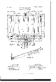
- Fig. 2 is a front View of the upper portion of the device.
- Fig. 3 isadetail perspective view of the lower rail or bar of one of the leafturners.
- Fig. l is a detail view of the devices for actuating the leaf-turners.
- Fig. 5 is a vertical sectional view of the upper portion of the device.
- the reference-numeral 1 designates a standard or upright having at its upper end an adjustable music-rack 2. At its lower end the upright is supported by a tripod 3. To the upper and lower sides of the rack 2, at the center thereof, are secured brackets 4, provided with upwardly-projecting studs 5, which form the journals of the leaf-turners. Nearthelo-wer edge of the rack, and upon each side of the center thereof, are cleats 6, having outwardly-projecting flanges 7, upon which a music-book is supported, the flanges 7 at their centers being cut away or recessed at S to receive a rubber strap 9.
- This strap is secured to the rack at its lower end, and when the book is in place is carried upward over the same and its free or upper end connected with a stud 10, secured to the rack, being provided with a loop 12 for that purpose.
- a stud 10 secured to the rack, being provided with a loop 12 for that purpose.
- the straps are only to engage with the backs of the book or those portions or leaves which are not to be turned.
- the rack is also provided with a series of cleats 13 for the book or music to rest against.
- the numeral 14L designates the leaf-turners, which may be of any desired number, and each consists of top and bottom rails 15 and 16, connected at their outer ends by means of vertical rails 17.
- the rails 15 and 16 are recessed at their inner ends and provided with extensions 18, having apertures to receive the studs 5, which form pivots for the same.
- Each of the bottom rails 10 is provided with four recesses 19, 2O, 21, and 22.
- At the inner walls of recesses 19 and 21 are oppositely-projecting beveled arms 23 and 24:. These may be formed by turning the strips cut to form said recesses at right angles to the rails, or they may be formed in any other manner found convenient or desirable.
- bracket 28 Secured to the lower side of the rack 2 is a bracket 28, in which are journaled two vertical rods 29, carrying, at their upper ends outwardly-projecting arms 30 and 31. These arms at their outer or free ends are provided or formed with upwardly-projecting beveled studs 32, which are adapted to engage with the gravity-gates in order to actuate the leafturners. These arms project in opposite directions-that is to say, one is arranged on one side of the center of the rack, while the other is located on the other sideand one 30 is shorter than the one 31, so as to engage with the gates nearest the inner ends of the leaf-turners, while the other is adapted to engage with the outermost gates.
- each of the rods 29 Secured to each of the rods 29 is a cogged segment- 33, which engages with a corresponding segment 34 on the inner end of a two-armed lever 35, pivoted in the bracket 28.
- These levers are provided with finger-plates 36 and also with a series of apertures 37 to receive the upper ends of chains 38.
- the lower ends of these chains are connected with treadles 2-39, pivoted to the downwardly-extending leg a0 of the tripod 8, coiled springs all being connected with the tripod and treadles, so as to return the latter to normal position after depression.
- coiled springs 42 Encircling the rod 29 are coiled springs 42, which serve to return the levers and arms to normal position after they have been actuated.
- the upper edges of the lower rails of the leaf-turners are provided with hooks 5 .4, with which are engaged rubber bands 45, which at their upper ends are connected with a stud 46 on the upper rail.
- the music-sheets are located between these rubber bands.
- a vertical strip 49 At each end of the rack is a vertical strip 49, having rubber cushions 50 at the top and bottom, which act as a buffer for the leafturner and take up the shock.
- Vhen the piece of music to be played is in a book, the latter is secured to the rack by means of the rubber straps 9,by passing said straps over the back of the book and such leaves as it is not desired to use.
- the leaves from which it is intended to be played are then connected with the leaf-turners by means of the rubber bands, one leaf to each of the turners or frames, by inserting the leaves between said bands.
- the straps 9 are not used, the leaves being inserted between the bands 45, as before stated.
- the leaf turners or frames are then arranged upon or turned over to one side (the right) of the rack, so that the first page to be played will be in proper position.
- the arms 23 will project through the recesses 19 and engage with the gravity-gates 25, cansing all of said gates, except the one on the outermost leaf-turner, to be elevated and thrown out of the path of the stud on the arm 30.
- the arm 30 is actuated either manually by depressing lever 35 or by means of one of the treadles 39, which, through the medium of the cogged segments and 34, causes said arm to be thrown outward, when the stud on the end thereof will come in contact with the gravity-gate 25 on the outermost leaf-turner and throw the latter over to the opposite side of the rack, displaying a new page of music.
- the projecting arm 23 thereon will leave the gate on the next adjoining leaf-turner, allowing said gate to fall down, so as to be engaged with the said arm when next operated.
- These arms 23 also serve as stops for the gates and limit the movement thereof. This operation can be repeated until all the leaves have been turned, the arms 24: on the opposite sides of the turners acting upon the opposite gates 26 in a similar manner, so as to have all of the latter, except the one on the turner last actuated, out of the path of the arms 31.
- the rack can also be disconnected from the up right or standard, so as to be placed upon a piano or organ, in which case the turners will be operated by the finger-pieces on the levers Having thus described my invention, what I claim is 1.
Landscapes
- Toys (AREA)
Description
(No Model.) 3 SheetsSheet 2. B. P. D. MILLER. MUSIC LEAP TURNER.
No. 463,529. Pitented Nov. 17,1891.
(No Model.) 3 SheetsSheet 3.. B. F. D. MILLER. MUSIC LEAF TURNER.
No. 463,529. Patented Nov. 17,1891.
wlwzafi: jwyamzn y I %fv/6a raw WIN 19828 H UNITED STATES PATENT OFFICE.
BENJAMIN F. D. MILLER, OF WOOSTER, OHIO.
MUSIC-LEAF TURNER.
SPECIFICATION forming part of Letters Patent No. 463,529, dated November 17, 1891.
Application filed April 8, 1891- Serial No. 388,086 (No model.)
To coZZ whom it may concern.-
Be it known that 1, BENJAMIN F. D. MILLER, a citizen of the United States, and a resident of lVooster, in the county of Wayne and State of Ohio, have invented certain new and useful Improvements in Music-Leaf Turners; and I do hereby declare that the following is a full, clear, and exact description of the invention, which will enable others skilled in the art to which it appertains to make and use the same, reference being had to the accompanying drawings, which form a part of this specification.
My invention relates to improvements in music-leaf turners.
The object of the invention is to providea reliable and efficient device for the above purpose, by means of which music may be turned either forward or backward, according to requirements, or as desired.
The invention consists in the novel construction and combination of parts hereinafter fully described, and definitely pointed out in the claims.
111 the accompanying drawings, Figure 1 is a perspective view of a music-leaf turner c011- structed in accordance with my invention.
Fig. 2 is a front View of the upper portion of the device. Fig. 3 isadetail perspective view of the lower rail or bar of one of the leafturners. Fig. l is a detail view of the devices for actuating the leaf-turners. Fig. 5 is a vertical sectional view of the upper portion of the device.
In the said drawings, the reference-numeral 1 designates a standard or upright having at its upper end an adjustable music-rack 2. At its lower end the upright is supported by a tripod 3. To the upper and lower sides of the rack 2, at the center thereof, are secured brackets 4, provided with upwardly-projecting studs 5, which form the journals of the leaf-turners. Nearthelo-wer edge of the rack, and upon each side of the center thereof, are cleats 6, having outwardly-projecting flanges 7, upon which a music-book is supported, the flanges 7 at their centers being cut away or recessed at S to receive a rubber strap 9. This strap is secured to the rack at its lower end, and when the book is in place is carried upward over the same and its free or upper end connected with a stud 10, secured to the rack, being provided with a loop 12 for that purpose. Of course it will be understood that the straps are only to engage with the backs of the book or those portions or leaves which are not to be turned. The rack is also provided with a series of cleats 13 for the book or music to rest against.
The numeral 14L designates the leaf-turners, which may be of any desired number, and each consists of top and bottom rails 15 and 16, connected at their outer ends by means of vertical rails 17. The rails 15 and 16 are recessed at their inner ends and provided with extensions 18, having apertures to receive the studs 5, which form pivots for the same. Each of the bottom rails 10 is provided with four recesses 19, 2O, 21, and 22. At the inner walls of recesses 19 and 21 are oppositely-projecting beveled arms 23 and 24:. These may be formed by turning the strips cut to form said recesses at right angles to the rails, or they may be formed in any other manner found convenient or desirable. Upon opposite sides of the rails are pivoted gravitygates 25 and 20, having recesses 27 at their lower inner ends. It will be seen that the arms 23 and 24 project through the recesses 19 and 21, so that their beveled ends will come in contact with the inner ends of the gates 25 and 26 of the adjoining leaves, so that all of said gates except those on the outermost leaf-turner will be out of line with the operating-arms, as hereinafter set forth.
Secured to the lower side of the rack 2 is a bracket 28, in which are journaled two vertical rods 29, carrying, at their upper ends outwardly-projecting arms 30 and 31. These arms at their outer or free ends are provided or formed with upwardly-projecting beveled studs 32, which are adapted to engage with the gravity-gates in order to actuate the leafturners. These arms project in opposite directions-that is to say, one is arranged on one side of the center of the rack, while the other is located on the other sideand one 30 is shorter than the one 31, so as to engage with the gates nearest the inner ends of the leaf-turners, while the other is adapted to engage with the outermost gates. Secured to each of the rods 29 is a cogged segment- 33, which engages with a corresponding segment 34 on the inner end of a two-armed lever 35, pivoted in the bracket 28. These levers are provided with finger-plates 36 and also with a series of apertures 37 to receive the upper ends of chains 38. The lower ends of these chains are connected with treadles 2-39, pivoted to the downwardly-extending leg a0 of the tripod 8, coiled springs all being connected with the tripod and treadles, so as to return the latter to normal position after depression. Encircling the rod 29 are coiled springs 42, which serve to return the levers and arms to normal position after they have been actuated. There is also a vertical rod 43 on the bracket 28, which prevents either of the arms 30 or 31 from being thrown past the center of said bracket.
The upper edges of the lower rails of the leaf-turners are provided with hooks 5 .4, with which are engaged rubber bands 45, which at their upper ends are connected with a stud 46 on the upper rail. The music-sheets are located between these rubber bands.
At each end of the rack is a vertical strip 49, having rubber cushions 50 at the top and bottom, which act as a buffer for the leafturner and take up the shock.
The operation is as follows: Vhen the piece of music to be played is in a book, the latter is secured to the rack by means of the rubber straps 9,by passing said straps over the back of the book and such leaves as it is not desired to use. The leaves from which it is intended to be played are then connected with the leaf-turners by means of the rubber bands, one leaf to each of the turners or frames, by inserting the leaves between said bands. Of course when loose leaves of music are employed the straps 9 are not used, the leaves being inserted between the bands 45, as before stated. The leaf turners or frames are then arranged upon or turned over to one side (the right) of the rack, so that the first page to be played will be in proper position. In turning these leaf turners or frames to such position the arms 23 will project through the recesses 19 and engage with the gravity-gates 25, cansing all of said gates, except the one on the outermost leaf-turner, to be elevated and thrown out of the path of the stud on the arm 30. \Vhen it is desired to turn the leaf, the arm 30 is actuated either manually by depressing lever 35 or by means of one of the treadles 39, which, through the medium of the cogged segments and 34, causes said arm to be thrown outward, when the stud on the end thereof will come in contact with the gravity-gate 25 on the outermost leaf-turner and throw the latter over to the opposite side of the rack, displaying a new page of music. As the leaf-turner is then aetuated,the projecting arm 23 thereon will leave the gate on the next adjoining leaf-turner, allowing said gate to fall down, so as to be engaged with the said arm when next operated. These arms 23 also serve as stops for the gates and limit the movement thereof. This operation can be repeated until all the leaves have been turned, the arms 24: on the opposite sides of the turners acting upon the opposite gates 26 in a similar manner, so as to have all of the latter, except the one on the turner last actuated, out of the path of the arms 31.
From the above it will be noted that by means of the arms 23 and 24*- and gates 25 and 20 that only the outermost leaf-turners or those which carry the exposed sheets of music will be actuated upon by depressing the levers 35, and that as said leaf-turners are actuated the gate on the next adjoining one will be broughtinto position to be engaged by the levers. From the above it will also be seen that the turners or frames can be shifted to the right or left of the rack, as desired, or according as the music is written,
and that, also, they may be actuated by hand or foot, as maybe found convenient. The rack can also be disconnected from the up right or standard, so as to be placed upon a piano or organ, in which case the turners will be operated by the finger-pieces on the levers Having thus described my invention, what I claim is 1. The combination, with a music rack or stand, of the pivoted leaf turners 0r frames the lower rails of which are provided with a series of recesses, the gravity-gates pivoted to opposite sides of said rails, the opposite outwardly-projecting beveled arms adapted to actuate said gates, the levers engaging with said gates, and means, substantially as de scribed, for operating said levers.
2. The combination, with a music rack or stand, of the pivoted leaf-turners having recesses in the lower rails, the gravity-gates pivoted to said rails, the oppositely-projecting beveled arms, the bracket secured to the rack, the vertical rods pivoted therein, hav ing the arms at their upper endsprovided with upwardly-extending lugs, the cogged segments on said rods, the pivoted levers having cogged segments at their upper ends, the chains, the pivoted treadles, and the coiled springs connected therewith, substantially as described.
3. The combination, with a music rack or stand, of the pivoted leaf-turners having a series of recesses in their lower rails, the gravity-gates pivoted to said rails and having recesses in their inner lower ends, the oppositely-projecting arms adapted to actuate said gates, the bracket secured to said rack or stand, the vertical rods pivoted in said brackets, the arms at the upper ends of said brackets having beveled studs on their outer ends, the cogged segments secured to said LOO IIO
my own I have hereunto aliixed my signature in presence of two Witnesses.
BENJAMIN F. D. MILLER.
Witnesses:
THOS. A. KAUFMAN, LYMAN R. ORITOHFIELD, Jr.
Publications (1)
| Publication Number | Publication Date |
|---|---|
| US463529A true US463529A (en) | 1891-11-17 |
Family
ID=2532401
Family Applications (1)
| Application Number | Title | Priority Date | Filing Date |
|---|---|---|---|
| US463529D Expired - Lifetime US463529A (en) | Music-leaf turner |
Country Status (1)
| Country | Link |
|---|---|
| US (1) | US463529A (en) |
-
0
- US US463529D patent/US463529A/en not_active Expired - Lifetime
Similar Documents
| Publication | Publication Date | Title |
|---|---|---|
| US463529A (en) | Music-leaf turner | |
| US826643A (en) | Music-leaf turner. | |
| US1104100A (en) | Copy-holder. | |
| US491907A (en) | Music-leaf turner | |
| US582050A (en) | Music-leaf turner | |
| US250881A (en) | Ville | |
| US805822A (en) | Sheet-music-leaf turner. | |
| US411431A (en) | Sylvania | |
| US1164570A (en) | Music-leaf turner. | |
| US1270114A (en) | Music-turner. | |
| US634279A (en) | Music-leaf turner. | |
| US472170A (en) | Music-leaf turner | |
| US604825A (en) | Thirds to arthur f | |
| US309683A (en) | James peecy batchelob | |
| US732496A (en) | Music-leaf turner. | |
| US653731A (en) | Music-leaf turner. | |
| US803548A (en) | Music-leaf turner. | |
| US1057418A (en) | Music-leaf turner. | |
| US882036A (en) | Music-leaf turner. | |
| US690395A (en) | Leaf-turner. | |
| US749667A (en) | Music-leaf turner | |
| US408977A (en) | Music-leaf turner | |
| US359566A (en) | Music-leaf turner | |
| US1253708A (en) | Music-leaf turner. | |
| US705023A (en) | Music-sheet turner. |