US4628362A - Combined video AGC and digitizing circuit - Google Patents
Combined video AGC and digitizing circuit Download PDFInfo
- Publication number
- US4628362A US4628362A US06/729,813 US72981385A US4628362A US 4628362 A US4628362 A US 4628362A US 72981385 A US72981385 A US 72981385A US 4628362 A US4628362 A US 4628362A
- Authority
- US
- United States
- Prior art keywords
- circuit
- pulse
- signal
- agc
- converter
- Prior art date
- Legal status (The legal status is an assumption and is not a legal conclusion. Google has not performed a legal analysis and makes no representation as to the accuracy of the status listed.)
- Expired - Lifetime
Links
Images
Classifications
-
- H—ELECTRICITY
- H04—ELECTRIC COMMUNICATION TECHNIQUE
- H04N—PICTORIAL COMMUNICATION, e.g. TELEVISION
- H04N5/00—Details of television systems
- H04N5/44—Receiver circuitry for the reception of television signals according to analogue transmission standards
- H04N5/52—Automatic gain control
-
- H—ELECTRICITY
- H04—ELECTRIC COMMUNICATION TECHNIQUE
- H04N—PICTORIAL COMMUNICATION, e.g. TELEVISION
- H04N5/00—Details of television systems
- H04N5/14—Picture signal circuitry for video frequency region
- H04N5/20—Circuitry for controlling amplitude response
Definitions
- the invention relates to an automatic gain control (AGC) and digitizing circuit particularly suitable for use in digital video image processing and/or display systems.
- AGC automatic gain control
- a video camera is used to produce an electrical representation of an image for many uses, one of which is to provide a video image on a remote monitor in security applications.
- a camera is placed at a particular location and scans a particular scene frequently over an extended period of time.
- background light which forms part of this scene frequently changes over this period.
- the video signal produced by the camera must be constantly adjusted whenever the background light changes. This requires that the gain and DC level of the video signal change in response to changes in the intensity of the background light; otherwise, the remotely displayed image will either be too light or too dark and hence difficult to perceive.
- a video signal is comprised of negative going horizontal and vertical synchronization pulses (hereinafter collectively referred to as the "synch" pulses) having a maximum peak amplitude of -0.4 volts which sandwich analog video (picture) information that varies between +1.0 volt, for a pure white signal, to 0.0 volts or ground, for a true black signal.
- AGC automatic gain control
- the video signal produced by a camera is digitized by a suitable analog-to-digital (A/D) converter prior to subsequent image processing and/or display.
- A/D analog-to-digital
- an AGC is essential in order to ensure that the picture information consumes the entire dynamic range of the A/D converter.
- DC restorer circuits look for the most negative voltage, and adjust the DC level of the video signal based on this voltage under the assumption that this voltage corresponds to the blackest area in the image when in actuality the most negative voltage actually corresponds to the negative peaks of the synch pulses. Since DC restorer type AGC circuits do not discriminate between true black signals on the one hand and the negative peaks of synch pulses on the other hand, these circuits unnecessarily compress the range of the video signal by upwards of 30-40%. Use of DC restorer circuits is particularly disadvantageous whenever the video signal is fed to an analog-to-digital (A/D) converter. Here, 30-40% of the dynamic range of the converter is needlessly lost by shifting the level of the entire video signal including the synch pulses--which carry no picture information--so that the entire signal lies within the useable range of the converter.
- A/D analog-to-digital
- AGC circuit feeds the video signal produced by a video camera through an analog multiplier, typically a transconductance amplifier.
- the AGC includes a detector which determines the brightest and darkest areas in the image, and adjusts the gain of the AGC, by appropriately varying the magnitude of one of the input voltages applied to the multiplier, so that the voltages corresponding to these areas never exceed a pre-selected range.
- this type of AGC circuit is not only extremely complex and expensive, but also exhibits non-linear performance inasmuch as analog multipliers--particularly transconductance amplifiers--possess some non-linearity.
- these AGC circuits require a viewer to properly adjust brightness and contrast controls in order to produce peak performance. Since few viewers know how to properly adjust these controls, such circuits often seem to produce inferior results.
- video AGC circuits known to the art which are employed in digital image processing systems, utilize the input analog voltage applied to the A/D converter as a feedback voltage to determine the proper amount of AGC gain and level change.
- these AGC circuits can not eliminate the small amounts of DC offset voltages that the A/D converter typically injects into its output signal.
- the background light which comprises only a portion of a scene will often change.
- that portion dependent upon where that portion is situated relative to the rest of the scene, it may not be desireable to alter the level of the video signal produced by the camera. For example, if that portion is in an area of no interest to a viewer but nonetheless becomes very bright and if the video signal is adjusted in response to this change in intensity, then the remainder of the image will become too dark and lose sufficient contrast to permit adequate viewing.
- any activity occurring in the area of interest will be not be readily detectable on a remote monitor.
- This circuit should: first, continuously modify the picture information, including its DC level, as well as change the gain of the converter, if necessary, to ensure that the picture information consumes the entire dynamic range of the converter; second, respond to light intensity changes occurring in any selected area of the scene and ignore changes occurring in other areas; and third, eliminate any offsets injected by the A/D converter.
- a particular object is to provide such a circuit which continuously modifies a video signal in order to ensure that the picture information consumes the entire dynamic range of the A/D converter.
- Another particular object is to provide such a circuit which adjusts the video signal to automatically compensate for any offset introduced by the A/D converter.
- a further object is to provide such an AGC circuit which, when operating on images containing sharply contrasting objects, does not display any "tilt".
- An additional object is to provide such an AGC circuit which exhibits extremely linear performance and also eliminates the need for a viewer to adjust the brightness and contrast controls in order to achieve optimum performance.
- An additional object is to provide such an AGC circuit which is both inexpensive and simple.
- this apparatus comprises: an analog-to-digital converter, having a dynamic range and a certain gain and operative in response to an intermediate input signal, for producing a digital output signal having digital values representing analog picture information contained in an incoming video signal; means, connected to the converter and operative in response to the incoming video signal and to at least one feedback signal, for producing the intermediate input signal and for ensuring that picture information contained in the intermediate input signal consumes substantially all of the dynamic range of the converter; means, operative in response to the occurrence of vertical and horizontal synchronization pulses, occurring in the incoming video signal, for providing an enable signal and for selectively varying the starting time and duration of the enable signal so as to selectively define an active window, within a video image, on which the AGC is to operate; and means, responsive to the digital output signal and to the enable signal, for comparing the digital
- the active window can be located anywhere within an active image area and can encompass any area from the entire image area to that of a single picture element by suitably adjusting the starting and duration times of the enable signal.
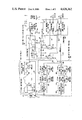
- FIG. 1 depicts a block diagram of a video AGC circuit embodying the principles of the present invention.
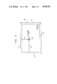
- FIG. 2 depicts a video image, as displayed on a monitor, having a pre-selected portion (the "active window") on which the AGC operates in accordance with the teachings of the invention.
- FIG. 1 A block diagram of a video automatic gain control (AGC) circuit constructed in accordance with the teachings of the present invention is shown in FIG. 1.
- AGC automatic gain control
- an input analog video signal 6 is applied to input 10 and, via leads 12 and 13, to gain and level adjusting circuit 15, and active window generator 100.
- Signal 6 is a typical analog video signal and includes synchronization pulses 9 ("synch" pulses) having a maximum peak amplitude of -0.4 volts.
- These synch pulses sandwich (analog video) picture information 7 that varies between +1.0 volt, for a pure white signal, to 0.0 volts or ground, for a true black signal.
- the magnitude of the picture information represents intensity changes; for color images, additional information is added into the video but this additional information does not change the maximum voltage limits.
- pulse 9a having a width of approximately 5 micro-seconds and occurring during vertical blanking interval 5
- pulse 9b having a width of approximately 180 micro-seconds
- the horizontal synchronization pulse is not drawn to scale.
- Gain and level adjusting circuit 15 dynamically varies both the range of multiplying analog-to-digital (A/D) converter 50 as well as the DC level of the analog video signal applied thereto in response to two feedback signals appearing over leads 92 and 96.
- the output of circuit 15 is applied as input to A/D converter 50.
- the feedback signals ensure that the picture information portion of the input analog video signal has the proper DC level and consumes the entire dynamic range of the A/D converter.
- Comparators 60 monitor the maximum and minimum values of the digitized video signal produced by converter 50 and, in response thereto, generate the feedback signals appearing over leads 92 and 96.
- AGC active window generator 100 detects the horizontal and vertical synch pulses, and, in response thereto, produces control signals which are applied over lead 175 to comparators 60. These control signals enable the operation of these comparators during a pre-selected window of time and thereby permit the AGC to be active during this time. As discussed in greater detail below, both the starting time and the duration of this window are fully adjustable. This advantageously permits the AGC to operate only on a pre-selected portion (the "active window") of a scanned video image.
- the active window can extend from the entire active video image, i.e. the entire displayed video image less the blanking areas, to any small area, such as that of a single picture element, located anywhere in the active image. As a result, the AGC ignores changes occurring in the remainder of the image thereby ensuring that the active window is displayed with proper brightness and contrast.
- input analog video signal 6 appearing over lead 12 is applied to the non-inverting input of amplifier 20 in circuit 15.
- This amplifier increases the maximum amplitude of the analog video signal to a pre-defined value, typically approximately 2 volts peak for the picture information.
- amplifier 20, as will become evident shortly, also shifts the DC level of the analog video signal to an appropriate level.
- the output of amplifier 20, also referred to as an intermediate input signal is applied as an analog input signal to analog input 25 of A/D converter 50.
- Converter 50 is a flash analog-to-digital converter which generates an illustratively 6 bit output corresponding to 64 different gray levels.
- the converter produces a digital signal on its parallel output leads 55 that is the digital equivalent of the intermediate input voltage with respect to the value of the positive and negative reference voltages also applied to the A/D.
- the A/D produces all zeroes (000000) for both zero-valued and all negative input voltages.
- the A/D produces all ones (111111).
- the positive reference voltage applied over lead 51 determines the magnitude of the intermediate input signal which, when applied to the A/D, will produce the maximum output
- the positive reference voltage in effect provides a gain control over the output of the A/D.
- the lower level of the A/D converter could be set by applying a non-zero voltage over lead 52; however, the A/D converter and amplifier 20 might be forced outside their useable voltage ranges as a result. By incorporating the DC level adjustment into amplifier 20 and ahead of the A/D converter, this out-of-range problem is advantageously avoided.
- the digitized video output word is applied in parallel over leads 55 to appropriate output terminals (not shown) and over leads 57 to an input of digital comparators 61 and 65.
- Comparator 61 serves as an upper threshold detector and provides an output signal whenever the value of the digitized video is maximum (111111).
- Comparator 65 serves as a lower threshold detector and provides an output signal whenever the value of the digitized video is minimum (000000).
- the output of both comparators, appearing over lead 96 for comparator 61 and lead 92 for comparator 65 are fed back as input to circuit 15.
- Maximum and minimum digital values, "111111” and "000000” are applied as input, via leads 63 and 67, to comparators 61 and 65, respectively.
- the feedback signals remain zero valued and, in response thereto, the gain of the A/D converter and DC level of the intermediate input signal are changed accordingly in order to ensure that the full dynamic range of converter 50 is used.
- comparator 65 does not generate a pulse over lead 92. The absence of such a pulse at the control input of switch 91 causes this switch to remain open. This permits the negative voltage level, -V, to be applied through resistor 81 to the input of integrator 30, comprised of amplifier 31 and integrating capacitor 32.
- this pulse When applied to the control input of switch 91, this pulse causes this switch to close thereby applying a positive voltage level, +V, through resistor 93 to the input of the integrator. Since the value of resistor 93 is much less than that of resistor 81, the integrator begins to ramp downward, thereby forcing the DC level of the intermediate input signal back up.
- the value of resistor 93 is chosen to be sufficiently large such that small negative spikes in the input analog video signal do not affect the DC level of the intermediate input signal.
- comparator 61 does not generate a pulse over lead 96.
- the absence of such a pulse at the control input of switch 95 causes this switch to remain open thereby permitting the negative voltage level, -V, to be applied through resistor 83 and across capacitor 43. This causes the voltage across this capacitor to ramp downward. Since this voltage is applied to the non-inverting input of unity gain amplifier 40, the output of this amplifier, referred to as a second control voltage, which is applied to the positive reference voltage input of the A/D converter, ramps negative. This, in turn, increases the gain of the A/D.
- capacitor 43 and resistor 83 are appropriately chosen such that their time constant is fairly slow, typically on the order of one second. As long as digitized video remains below all ones, then capacitor 43 continues to charge negatively through resistor 83. Once the digitized output reaches all ones, comparator 61 produces a positive pulse which closes switch 95 and, in turn, applies a positive voltage through resistor 97 across capacitor 43. Since the value of resistor 97 is much less than that of resistor 83, the capacitor voltage begins to ramp upward thereby forcing the positive reference voltage of the A/D upward and the gain of the A/D converter downward. The value of resistor 97 is chosen to be sufficiently large such that small positive spikes in the input analog video signal do not affect the DC level of the second control voltage.
- the maximum gain of the A/D converter is limited by preventing the positive reference voltage from decreasing all the way to zero. This is facilitated by limiting the negative voltage applied to the input of amplifier 40 through any one of many well-known means (not shown).
- AGC active window generator 100 enables comparators 61 and 65 for certain periods of time such that the AGC only operates on a desired portion of the image (i.e. the active window)--and not on the remainder of the image or on the blanking areas.
- an analog video signal contains synch pulses: a fairly wide negative vertical synch pulse 9b (typically on the order of 180 micro-seconds in width) occurring once per field followed by a fairly narrow negative horizontal synch pulse 9a (typically on the order of 5 micro-seconds in width) occurring once per line. Both of these synch pulses are detected within AGC active window generator 100 by well-known horizontal and vertical synch pulse detectors 110 and 120.
- Each such detector produces a short pulse upon the occurrence of its respective synch pulse.
- the top vertical blanking area (at the top of a displayed video image) is approximately 1 millisecond in duration and the left horizontal blanking area (to the left of a displayed video image) is approximately 10 micro-seconds. Since no picture information is transmitted during either of these times, the AGC must not be active during these blanking intervals. To accomplish this, the enable signal appearing on lead 175 is delayed by a period of time at least as long as these intervals.
- the output of vertical synch pulse detector 120 is applied, over lead 125, to one-shot (monostable multivibrator) 140 which produces a pulse at least 1 milli-second later than the occurrence of the vertical synch pulse.
- the delay produced by one-shot 140 can be increased.
- This one-shot determines where, measured downward from the top of the image, the AGC is to become active.
- the AGC can be set to become active on any pre-determined horizontal scan line situated below the top vertical blanking area.
- the pulse produced by one-shot 140 is applied as input, via lead 145, to one-shot 160.
- This latter one-shot generates a pulse which determines the maximum interval of time throughout which the AGC is to be active during each displayed image. Consequently, the AGC operates on all scan lines that occur between the start and termination of the pulse produced by one-shot 160.
- this time interval can be varied and hence the AGC can be set to operate on any number of contiguous scan lines extending to any depth below the pre-determined scan line.
- cascaded one-shots 130 and 150 driven by the output of horizontal synch pulse detector 110 applied over lead 115, determine the particular portion of each of the selected contiguous horizontal scan lines during which the AGC is to operate. This portion can be set to encompass any continuous segment of a scan line.
- one-shot 130 provides at least a 10 micro-second delay to inhibit the AGC from operating during at least the left horizontal blanking area. Potentiometer 133 can be suitably varied to extend this delay to inhibit the AGC from operating until any point is reached along a scan line.
- One-shot 150 determines the period of time during which the AGC is to be active during each selected scan line. This time period can be varied by suitably adjusting potentiometer 153.
- the outputs from one-shots 150 and 160 are applied over leads 155 and 165 to respective inputs of AND gate 170.
- the output of this gate is a pulse occurring once during each of the pre-selected contiguous horizontal scan lines which, when fed over lead 175 to the enable inputs of comparators 61 and 65, enables both comparators and hence allows the AGC to operate during only a pre-selected portion of each these scan lines.
- a box, within which the AGC operates is electrically defined within active video image area 210. This box is active window 220.
- the active video image area together with the horizontal blanking areas 201 and 203 and the vertical blanking areas 205 and 207 comprise the entire image 200 sent to a video monitor.
- the amount of horizontal spacing 230 from horizontal blanking area 201 and/or vertical spacing 240 from vertical blanking area 205 to the active window 220 can be varied accordingly.
- the active window can be located anywhere within the video image area.
- the width and height of the active window can be separately varied by appropriately adjusting window width and height adjust potentiometers 153 and 163 to change the dimensions of the window, in the directions shown by arrows 225, in order to encompass any area from that a single picture element (pixel) to that of the entire picture.
- the inventive video AGC and digitizing circuit described above continuously, simultaneously and independently adjusts both the gain of the A/D converter and the DC level of the analog video signal (specifically, that of the picture information) applied to the A/D converter in order to utilize the full dynamic range of the converter and hence produce a proper image of the active window under all input signal conditions--regardless of whether the active window is set to be the entire video image or any pre-selected portion thereof.
- the active window adjustments can be achieved not only by using potentiometers, but also by applying suitable control voltages, to well-known circuitry in order to vary the time-periods of the respective one-shots.
- control voltages can advantageously be produced by other circuitry so as to automatically choose the proper position and size for the active window.
- the digitized video output can be routed to a motion detector which performs a frame-by-frame comparison to detect any motion occurring anywhere within the scanned image.
- the detector or other circuitry such as a computer, could generate suitable control voltages to automatically locate the active window over the portion of the image in which the motion has occurred in order to ensure that at least that portion is displayed with proper brightness and contrast.
- the shape of the active window can be changed from rectangular to any other shape, such as circular, by suitably changing the time at which the pulses produced by the active window generator occur and their duration.
- the horizontal scan lines comprising the active window need not be contiguous. In fact, the active window can be readily set to encompass any number of isolated portions of the image area.
Landscapes
- Engineering & Computer Science (AREA)
- Multimedia (AREA)
- Signal Processing (AREA)
- Picture Signal Circuits (AREA)
- Television Receiver Circuits (AREA)
Abstract
Description
Claims (17)
Priority Applications (1)
| Application Number | Priority Date | Filing Date | Title |
|---|---|---|---|
| US06/729,813 US4628362A (en) | 1985-05-02 | 1985-05-02 | Combined video AGC and digitizing circuit |
Applications Claiming Priority (1)
| Application Number | Priority Date | Filing Date | Title |
|---|---|---|---|
| US06/729,813 US4628362A (en) | 1985-05-02 | 1985-05-02 | Combined video AGC and digitizing circuit |
Publications (1)
| Publication Number | Publication Date |
|---|---|
| US4628362A true US4628362A (en) | 1986-12-09 |
Family
ID=24932736
Family Applications (1)
| Application Number | Title | Priority Date | Filing Date |
|---|---|---|---|
| US06/729,813 Expired - Lifetime US4628362A (en) | 1985-05-02 | 1985-05-02 | Combined video AGC and digitizing circuit |
Country Status (1)
| Country | Link |
|---|---|
| US (1) | US4628362A (en) |
Cited By (43)
| Publication number | Priority date | Publication date | Assignee | Title |
|---|---|---|---|---|
| US4695885A (en) * | 1984-12-28 | 1987-09-22 | Kim Joo W | Automatic brightness control device |
| US4745479A (en) * | 1985-10-04 | 1988-05-17 | American Dynamics Corporation | Multiple image video display system |
| DE3818125A1 (en) * | 1987-05-27 | 1988-12-08 | Olympus Optical Co | LIGHT CONTROL DEVICE FOR ENDOSCOPES |
| US4855830A (en) * | 1987-03-30 | 1989-08-08 | Allen-Bradley Company, Inc. | Machine vision system with illumination variation compensation |
| US4860103A (en) * | 1985-10-09 | 1989-08-22 | British Telecommunications Plc | Video level control |
| US4884140A (en) * | 1987-11-18 | 1989-11-28 | Goldstar Co., Ltd. | Vignetting compensating circuit for a video camera |
| US4951135A (en) * | 1988-01-11 | 1990-08-21 | Olympus Optical Co., Ltd. | Electronic-type endoscope system having capability of setting AGC variation region |
| US4977460A (en) * | 1987-04-30 | 1990-12-11 | Nec Home Electronics Ltd. | Video signal reproducing apparatus having setup level elimination |
| US4984085A (en) * | 1989-08-03 | 1991-01-08 | Allen-Bradley Company, Inc. | Image processor with dark current compensation |
| EP0419341A1 (en) * | 1989-09-22 | 1991-03-27 | Laboratoire Europeen De Recherches Electroniques Avancees | Video signal receiving equipment |
| DE4038220A1 (en) * | 1989-12-04 | 1991-06-13 | Allen Bradley Co | METHOD AND ARRANGEMENT FOR COMPENSATING AN IMAGE SIGNAL AGAINST LIGHTING CHANGES |
| EP0381119A3 (en) * | 1989-02-01 | 1991-10-16 | Canon Kabushiki Kaisha | Image sensing device |
| US5087976A (en) * | 1989-11-10 | 1992-02-11 | Sony Corporation | Automatic adjustment apparatus for independently adjusting different regions of a picture raster |
| US5091779A (en) * | 1989-08-25 | 1992-02-25 | Richard Wolf Gmbh | Automatic light adjustment means for an endoscope |
| US5214418A (en) * | 1988-12-22 | 1993-05-25 | Mitsubishi Denki Kabushiki Kaisha | Liquid crystal display device |
| US5237408A (en) * | 1991-08-02 | 1993-08-17 | Presearch Incorporated | Retrofitting digital video surveillance system |
| US5267331A (en) * | 1990-07-26 | 1993-11-30 | Ronald Siwoff | Digitally enhanced imager for the visually impaired |
| US5268761A (en) * | 1992-08-19 | 1993-12-07 | Rca Thomson Licensing Corporation | Automatic gain control system for a high definition television signal receiver including an adaptive equalizer |
| US5291276A (en) * | 1991-08-29 | 1994-03-01 | Sony Corporation | Apparatus for processing a video signal to generate video signal adjustment data that is self-contained with the video equipment |
| US5432550A (en) * | 1993-03-23 | 1995-07-11 | Daewoo Electronic Co., Ltd. | Camcorder equipped with a function for correcting brightness on the sides of a screen |
| US5486874A (en) * | 1994-05-13 | 1996-01-23 | Magma, Inc. | Method and apparatus for improving transmitted video signal structure |
| US5540097A (en) * | 1991-04-25 | 1996-07-30 | Olympus Optical Co., Ltd. | Ultrasonic microscope apparatus |
| US5565916A (en) * | 1992-12-23 | 1996-10-15 | Eastman Kodak Company | Automatic channel gain and offset balance for video cameras employing multi-channel sensors |
| US5598225A (en) * | 1994-05-13 | 1997-01-28 | Magma, Inc. | Method and apparatus for improving transmitted video signal structure |
| US5717469A (en) * | 1994-06-30 | 1998-02-10 | Agfa-Gevaert N.V. | Video frame grabber comprising analog video signals analysis system |
| US5757436A (en) * | 1996-06-21 | 1998-05-26 | Magma, Inc. | Image processor system |
| US5905541A (en) * | 1995-10-06 | 1999-05-18 | Lg Semicon Co., Ltd. | Television picture image processing apparatus |
| EP0854646A3 (en) * | 1997-01-17 | 1999-10-20 | Samsung Electronics Co., Ltd. | Digital automatic gain control (AGC) circuit |
| US6219107B1 (en) * | 1997-12-22 | 2001-04-17 | Texas Instruments Incorporated | Automatic AGC bias voltage calibration in a video decoder |
| EP1071281A4 (en) * | 1998-03-06 | 2001-08-22 | Matsushita Electric Industrial Co Ltd | AUTOMATIC LUMINANCE ADJUSTING DEVICE AND RELATED METHOD |
| WO2001043068A3 (en) * | 1999-12-01 | 2002-03-21 | Ball Aerospace & Tech Corp | Electronic image processing technique for achieving enhanced image detail |
| WO2004021277A1 (en) * | 2002-08-28 | 2004-03-11 | Koninklijke Philips Electronics N.V. | Method and arrangement for watermark detection |
| EP1067776A3 (en) * | 1999-07-05 | 2004-03-17 | Alps Electric Co., Ltd. | Image display apparatus for fixing luminance of blank area and varying only luminance of image. |
| US20040104886A1 (en) * | 2000-08-25 | 2004-06-03 | International Business Machines Corporation | Brightness controlling apparatus, brightness adjusting system, computer system, liquid crystal display unit, brightness controlling method, computer software, and storage medium |
| US20040207760A1 (en) * | 2001-11-01 | 2004-10-21 | Filliman Paul Dean | Method for dynamic contrast improvement |
| US20050111700A1 (en) * | 2003-10-03 | 2005-05-26 | O'boyle Michael E. | Occupant detection system |
| US20050195645A1 (en) * | 1998-03-09 | 2005-09-08 | Roger Panicacci | Readout circuit with gain and analog-to-digital conversion for image sensor |
| US20060077303A1 (en) * | 2004-10-13 | 2006-04-13 | Cirrus Logic, Inc. | Method and apparatus to improve ADC dynamic range in a video decoder |
| US7075590B1 (en) * | 1998-09-30 | 2006-07-11 | Thomson Licensing | Apparatus for providing television receiver alignment functions |
| US7136098B1 (en) * | 1998-10-23 | 2006-11-14 | Smith & Nephew, Inc. | Image illumination optimizing |
| US20070008426A1 (en) * | 2005-06-28 | 2007-01-11 | Realtek Semiconductor Corp. | Apparatus and method for detecting vertical blanking interval |
| US20090010495A1 (en) * | 2004-07-26 | 2009-01-08 | Automotive Systems Laboratory, Inc. | Vulnerable Road User Protection System |
| US20090033800A1 (en) * | 2007-07-31 | 2009-02-05 | Yagi Tatsuaki | Motion vector detection device and motion vector detection method |
Citations (12)
| Publication number | Priority date | Publication date | Assignee | Title |
|---|---|---|---|---|
| US3257506A (en) * | 1962-05-12 | 1966-06-21 | Fernseh Gmbh | Controlled contrast television apparatus |
| US3909521A (en) * | 1972-03-06 | 1975-09-30 | Spectrotherm Corp | Infrared imaging system |
| SU684781A1 (en) * | 1977-11-09 | 1979-09-05 | Ленинградский Электротехнический Институт Связи Им. Проф. М.А.Бончбруевича | Apparatus for restoring intermediate line of tv image |
| US4318129A (en) * | 1980-06-30 | 1982-03-02 | Hughes Aircraft Company | Automatic level and gain control system |
| US4363976A (en) * | 1981-01-19 | 1982-12-14 | Rockwell International Corporation | Subinterval sampler |
| US4402087A (en) * | 1979-07-20 | 1983-08-30 | Sumitomo Electric Industries, Ltd. | Binary coding circuit |
| JPS5922488A (en) * | 1982-07-29 | 1984-02-04 | Toshiba Corp | Automatic gain control circuit |
| US4434439A (en) * | 1982-02-22 | 1984-02-28 | Rca Corporation | Digital television AGC arrangement |
| US4517586A (en) * | 1982-11-23 | 1985-05-14 | Rca Corporation | Digital television receiver with analog-to-digital converter having time multiplexed gain |
| US4523232A (en) * | 1982-03-24 | 1985-06-11 | Casio Computer Co., Ltd. | Video signal analog-to-digital converter for an image display apparatus |
| US4525741A (en) * | 1982-11-03 | 1985-06-25 | Ncr Corporation | Self-adjusting video camera |
| US4540974A (en) * | 1981-10-30 | 1985-09-10 | Rca Corporation | Adaptive analog-to-digital converter |
-
1985
- 1985-05-02 US US06/729,813 patent/US4628362A/en not_active Expired - Lifetime
Patent Citations (12)
| Publication number | Priority date | Publication date | Assignee | Title |
|---|---|---|---|---|
| US3257506A (en) * | 1962-05-12 | 1966-06-21 | Fernseh Gmbh | Controlled contrast television apparatus |
| US3909521A (en) * | 1972-03-06 | 1975-09-30 | Spectrotherm Corp | Infrared imaging system |
| SU684781A1 (en) * | 1977-11-09 | 1979-09-05 | Ленинградский Электротехнический Институт Связи Им. Проф. М.А.Бончбруевича | Apparatus for restoring intermediate line of tv image |
| US4402087A (en) * | 1979-07-20 | 1983-08-30 | Sumitomo Electric Industries, Ltd. | Binary coding circuit |
| US4318129A (en) * | 1980-06-30 | 1982-03-02 | Hughes Aircraft Company | Automatic level and gain control system |
| US4363976A (en) * | 1981-01-19 | 1982-12-14 | Rockwell International Corporation | Subinterval sampler |
| US4540974A (en) * | 1981-10-30 | 1985-09-10 | Rca Corporation | Adaptive analog-to-digital converter |
| US4434439A (en) * | 1982-02-22 | 1984-02-28 | Rca Corporation | Digital television AGC arrangement |
| US4523232A (en) * | 1982-03-24 | 1985-06-11 | Casio Computer Co., Ltd. | Video signal analog-to-digital converter for an image display apparatus |
| JPS5922488A (en) * | 1982-07-29 | 1984-02-04 | Toshiba Corp | Automatic gain control circuit |
| US4525741A (en) * | 1982-11-03 | 1985-06-25 | Ncr Corporation | Self-adjusting video camera |
| US4517586A (en) * | 1982-11-23 | 1985-05-14 | Rca Corporation | Digital television receiver with analog-to-digital converter having time multiplexed gain |
Cited By (60)
| Publication number | Priority date | Publication date | Assignee | Title |
|---|---|---|---|---|
| US4695885A (en) * | 1984-12-28 | 1987-09-22 | Kim Joo W | Automatic brightness control device |
| US4745479A (en) * | 1985-10-04 | 1988-05-17 | American Dynamics Corporation | Multiple image video display system |
| US4860103A (en) * | 1985-10-09 | 1989-08-22 | British Telecommunications Plc | Video level control |
| US4855830A (en) * | 1987-03-30 | 1989-08-08 | Allen-Bradley Company, Inc. | Machine vision system with illumination variation compensation |
| US4977460A (en) * | 1987-04-30 | 1990-12-11 | Nec Home Electronics Ltd. | Video signal reproducing apparatus having setup level elimination |
| US4868645A (en) * | 1987-05-27 | 1989-09-19 | Olympus Optical Co., Ltd. | Light control device for endoscope |
| DE3818125A1 (en) * | 1987-05-27 | 1988-12-08 | Olympus Optical Co | LIGHT CONTROL DEVICE FOR ENDOSCOPES |
| US4884140A (en) * | 1987-11-18 | 1989-11-28 | Goldstar Co., Ltd. | Vignetting compensating circuit for a video camera |
| US4951135A (en) * | 1988-01-11 | 1990-08-21 | Olympus Optical Co., Ltd. | Electronic-type endoscope system having capability of setting AGC variation region |
| US5214418A (en) * | 1988-12-22 | 1993-05-25 | Mitsubishi Denki Kabushiki Kaisha | Liquid crystal display device |
| EP0381119A3 (en) * | 1989-02-01 | 1991-10-16 | Canon Kabushiki Kaisha | Image sensing device |
| US4984085A (en) * | 1989-08-03 | 1991-01-08 | Allen-Bradley Company, Inc. | Image processor with dark current compensation |
| US5091779A (en) * | 1989-08-25 | 1992-02-25 | Richard Wolf Gmbh | Automatic light adjustment means for an endoscope |
| US5157493A (en) * | 1989-09-22 | 1992-10-20 | Laboratoire Europeen De Recherches Electroniques Appliquees Societe En Nom Collectif | Synch responsive agc utilizing a-d converter |
| EP0419341A1 (en) * | 1989-09-22 | 1991-03-27 | Laboratoire Europeen De Recherches Electroniques Avancees | Video signal receiving equipment |
| FR2652473A1 (en) * | 1989-09-22 | 1991-03-29 | Europ Rech Electr Lab | EQUIPMENT FOR RECEIVING VIDEO SIGNALS. |
| US5087976A (en) * | 1989-11-10 | 1992-02-11 | Sony Corporation | Automatic adjustment apparatus for independently adjusting different regions of a picture raster |
| DE4038220A1 (en) * | 1989-12-04 | 1991-06-13 | Allen Bradley Co | METHOD AND ARRANGEMENT FOR COMPENSATING AN IMAGE SIGNAL AGAINST LIGHTING CHANGES |
| DE4038220C2 (en) * | 1989-12-04 | 2000-01-13 | Allen Bradley Co | Method and arrangement for compensating an image signal against changes in lighting |
| US5267331A (en) * | 1990-07-26 | 1993-11-30 | Ronald Siwoff | Digitally enhanced imager for the visually impaired |
| US5540097A (en) * | 1991-04-25 | 1996-07-30 | Olympus Optical Co., Ltd. | Ultrasonic microscope apparatus |
| US5237408A (en) * | 1991-08-02 | 1993-08-17 | Presearch Incorporated | Retrofitting digital video surveillance system |
| US5291276A (en) * | 1991-08-29 | 1994-03-01 | Sony Corporation | Apparatus for processing a video signal to generate video signal adjustment data that is self-contained with the video equipment |
| US5268761A (en) * | 1992-08-19 | 1993-12-07 | Rca Thomson Licensing Corporation | Automatic gain control system for a high definition television signal receiver including an adaptive equalizer |
| US5565916A (en) * | 1992-12-23 | 1996-10-15 | Eastman Kodak Company | Automatic channel gain and offset balance for video cameras employing multi-channel sensors |
| US5432550A (en) * | 1993-03-23 | 1995-07-11 | Daewoo Electronic Co., Ltd. | Camcorder equipped with a function for correcting brightness on the sides of a screen |
| US5486874A (en) * | 1994-05-13 | 1996-01-23 | Magma, Inc. | Method and apparatus for improving transmitted video signal structure |
| US5598225A (en) * | 1994-05-13 | 1997-01-28 | Magma, Inc. | Method and apparatus for improving transmitted video signal structure |
| US5717469A (en) * | 1994-06-30 | 1998-02-10 | Agfa-Gevaert N.V. | Video frame grabber comprising analog video signals analysis system |
| US5905541A (en) * | 1995-10-06 | 1999-05-18 | Lg Semicon Co., Ltd. | Television picture image processing apparatus |
| US5757436A (en) * | 1996-06-21 | 1998-05-26 | Magma, Inc. | Image processor system |
| EP0854646A3 (en) * | 1997-01-17 | 1999-10-20 | Samsung Electronics Co., Ltd. | Digital automatic gain control (AGC) circuit |
| US6219107B1 (en) * | 1997-12-22 | 2001-04-17 | Texas Instruments Incorporated | Automatic AGC bias voltage calibration in a video decoder |
| EP1071281A4 (en) * | 1998-03-06 | 2001-08-22 | Matsushita Electric Industrial Co Ltd | AUTOMATIC LUMINANCE ADJUSTING DEVICE AND RELATED METHOD |
| US7245321B2 (en) * | 1998-03-09 | 2007-07-17 | Micron Technology, Inc. | Readout circuit with gain and analog-to-digital conversion for image sensor |
| US20050195645A1 (en) * | 1998-03-09 | 2005-09-08 | Roger Panicacci | Readout circuit with gain and analog-to-digital conversion for image sensor |
| US7075590B1 (en) * | 1998-09-30 | 2006-07-11 | Thomson Licensing | Apparatus for providing television receiver alignment functions |
| US7136098B1 (en) * | 1998-10-23 | 2006-11-14 | Smith & Nephew, Inc. | Image illumination optimizing |
| EP1067776A3 (en) * | 1999-07-05 | 2004-03-17 | Alps Electric Co., Ltd. | Image display apparatus for fixing luminance of blank area and varying only luminance of image. |
| US6567124B1 (en) * | 1999-12-01 | 2003-05-20 | Ball Aerospace & Technologies Corp. | Electronic image processing technique for achieving enhanced image detail |
| WO2001043068A3 (en) * | 1999-12-01 | 2002-03-21 | Ball Aerospace & Tech Corp | Electronic image processing technique for achieving enhanced image detail |
| US20040104886A1 (en) * | 2000-08-25 | 2004-06-03 | International Business Machines Corporation | Brightness controlling apparatus, brightness adjusting system, computer system, liquid crystal display unit, brightness controlling method, computer software, and storage medium |
| US20040104919A1 (en) * | 2000-08-25 | 2004-06-03 | International Business Machines Corporation | Brightness controlling apparatus, brightness adjusting system, computer system, liquid crystal display unit, brightness controlling method, computer software, and storage medium |
| US7064794B2 (en) * | 2001-11-01 | 2006-06-20 | Thomson Licensing | Method for dynamic contrast improvement |
| US20040207760A1 (en) * | 2001-11-01 | 2004-10-21 | Filliman Paul Dean | Method for dynamic contrast improvement |
| US20060126887A1 (en) * | 2002-08-28 | 2006-06-15 | Talstra Johan C | Method and arrangement for watermark detection |
| US7561715B2 (en) * | 2002-08-28 | 2009-07-14 | Koninklijke Philips Electronics N.V. | Method and arrangement for watermark detection |
| WO2004021277A1 (en) * | 2002-08-28 | 2004-03-11 | Koninklijke Philips Electronics N.V. | Method and arrangement for watermark detection |
| US20050111700A1 (en) * | 2003-10-03 | 2005-05-26 | O'boyle Michael E. | Occupant detection system |
| US7406181B2 (en) | 2003-10-03 | 2008-07-29 | Automotive Systems Laboratory, Inc. | Occupant detection system |
| US20090010495A1 (en) * | 2004-07-26 | 2009-01-08 | Automotive Systems Laboratory, Inc. | Vulnerable Road User Protection System |
| US8509523B2 (en) | 2004-07-26 | 2013-08-13 | Tk Holdings, Inc. | Method of identifying an object in a visual scene |
| US8594370B2 (en) | 2004-07-26 | 2013-11-26 | Automotive Systems Laboratory, Inc. | Vulnerable road user protection system |
| US7324162B2 (en) * | 2004-10-13 | 2008-01-29 | Cirrus Logic, Inc. | Method and apparatus to improve ADC dynamic range in a video decoder |
| US20060077303A1 (en) * | 2004-10-13 | 2006-04-13 | Cirrus Logic, Inc. | Method and apparatus to improve ADC dynamic range in a video decoder |
| US20070008426A1 (en) * | 2005-06-28 | 2007-01-11 | Realtek Semiconductor Corp. | Apparatus and method for detecting vertical blanking interval |
| US7986370B2 (en) * | 2005-06-28 | 2011-07-26 | Realtek Semiconductor Corp. | Apparatus and method for detecting vertical blanking interval |
| US20090033800A1 (en) * | 2007-07-31 | 2009-02-05 | Yagi Tatsuaki | Motion vector detection device and motion vector detection method |
| EP2026575A3 (en) * | 2007-07-31 | 2009-02-25 | Sony Corporation | Motion vector detection device and motion vector detection method |
| US8126059B2 (en) | 2007-07-31 | 2012-02-28 | Sony Corporation | Motion vector detection device and motion vector detection method |
Similar Documents
| Publication | Publication Date | Title |
|---|---|---|
| US4628362A (en) | Combined video AGC and digitizing circuit | |
| US4811101A (en) | Black level correction circuit for correcting black level of a video signal | |
| US3691302A (en) | Automatic light control for low light level television camera | |
| US5504538A (en) | Video signal processor for controlling the brightness and contrast of a display device | |
| US4911552A (en) | Digital signal processing circuit for digital camera | |
| US5422680A (en) | Non-linear contrast control apparatus with pixel distribution measurement for video display system | |
| US4651210A (en) | Adjustable gamma controller | |
| KR930002609B1 (en) | Brightness and contrast adjusting apparatus | |
| EP0400605B1 (en) | Automatic gain control circuit for use in a television camera | |
| US5214418A (en) | Liquid crystal display device | |
| GB2086687A (en) | Automatic video signal level control circuit | |
| GB1049641A (en) | Circuit arrangement for varying the contrast of a television picture | |
| US4450476A (en) | Delayed reaction automatic kinescope biasing system | |
| EP0700208B1 (en) | Automatic brightness contrast lighting circuits and luminance/color difference signal processor and video display apparatus comprising the same | |
| US4535364A (en) | Spot exposure adjustment circuit | |
| CA1136756A (en) | Stabilized automatic brightness control network in a video signal processing system including an automatic kinescope beam current limiter | |
| US3737571A (en) | Automatic dark current control | |
| US4298886A (en) | Automatic peak beam current leveler system | |
| JPS6298388A (en) | Data display video monitor | |
| US4135200A (en) | Brightness control circuit with predictable brightness control range | |
| US5502508A (en) | Gradation compensating apparatus for a video signal | |
| US3445590A (en) | Coordinated sensitivity and amplification control system | |
| US3867010A (en) | Vertical interval reference signal extraction circuit arrangement | |
| FI73559C (en) | Interrupt compensated automatic beam current limiter for an image tube. | |
| JPH03145287A (en) | Video signal receiving system |
Legal Events
| Date | Code | Title | Description |
|---|---|---|---|
| AS | Assignment |
Owner name: AMERICAN DYNAMICS CORPORATION 126 NORTH ROUTE 303 Free format text: ASSIGNMENT OF ASSIGNORS INTEREST.;ASSIGNOR:WAEHNER, GLENN C.;REEL/FRAME:004408/0611 Effective date: 19850425 |
|
| STCF | Information on status: patent grant |
Free format text: PATENTED CASE |
|
| FPAY | Fee payment |
Year of fee payment: 4 |
|
| FEPP | Fee payment procedure |
Free format text: PAT HLDR NO LONGER CLAIMS SMALL ENT STAT AS SMALL BUSINESS (ORIGINAL EVENT CODE: LSM2); ENTITY STATUS OF PATENT OWNER: LARGE ENTITY |
|
| FEPP | Fee payment procedure |
Free format text: PAYOR NUMBER ASSIGNED (ORIGINAL EVENT CODE: ASPN); ENTITY STATUS OF PATENT OWNER: LARGE ENTITY |
|
| FPAY | Fee payment |
Year of fee payment: 8 |
|
| FPAY | Fee payment |
Year of fee payment: 12 |
|
| AS | Assignment |
Owner name: SENSORMATIC ELECTRONICS CORPORATION, FLORIDA Free format text: MERGER/CHANGE OF NAME;ASSIGNOR:SENSORMATIC ELECTRONICS CORPORATION;REEL/FRAME:012991/0641 Effective date: 20011113 Owner name: SENSORMATIC ELECTRONICS CORPORATION, FLORIDA Free format text: MERGER;ASSIGNOR:AMERICAN DYNAMICS;REEL/FRAME:013000/0608 Effective date: 19960930 |