US4626640A - Microwave arrangement for heating material - Google Patents
Microwave arrangement for heating material Download PDFInfo
- Publication number
- US4626640A US4626640A US06/779,770 US77977085A US4626640A US 4626640 A US4626640 A US 4626640A US 77977085 A US77977085 A US 77977085A US 4626640 A US4626640 A US 4626640A
- Authority
- US
- United States
- Prior art keywords
- resonator
- microwave
- cylindrical
- arrangement
- curved path
- Prior art date
- Legal status (The legal status is an assumption and is not a legal conclusion. Google has not performed a legal analysis and makes no representation as to the accuracy of the status listed.)
- Expired - Fee Related
Links
- 239000000463 material Substances 0.000 title claims abstract description 90
- 238000010438 heat treatment Methods 0.000 title claims abstract description 19
- 238000001035 drying Methods 0.000 claims abstract description 8
- 238000010924 continuous production Methods 0.000 claims abstract description 3
- 230000005284 excitation Effects 0.000 claims description 7
- 230000004323 axial length Effects 0.000 claims description 3
- 230000008878 coupling Effects 0.000 claims description 3
- 238000010168 coupling process Methods 0.000 claims description 3
- 238000005859 coupling reaction Methods 0.000 claims description 3
- 238000007599 discharging Methods 0.000 claims description 2
- 230000005684 electric field Effects 0.000 description 9
- 230000017525 heat dissipation Effects 0.000 description 7
- 230000015556 catabolic process Effects 0.000 description 4
- 239000000126 substance Substances 0.000 description 4
- 230000005855 radiation Effects 0.000 description 2
- 229920000742 Cotton Polymers 0.000 description 1
- 239000004809 Teflon Substances 0.000 description 1
- 229920006362 Teflon® Polymers 0.000 description 1
- 238000001723 curing Methods 0.000 description 1
- 238000006073 displacement reaction Methods 0.000 description 1
- 230000000694 effects Effects 0.000 description 1
- 238000001704 evaporation Methods 0.000 description 1
- 239000004744 fabric Substances 0.000 description 1
- 239000004753 textile Substances 0.000 description 1
- XLYOFNOQVPJJNP-UHFFFAOYSA-N water Substances O XLYOFNOQVPJJNP-UHFFFAOYSA-N 0.000 description 1
- 238000004804 winding Methods 0.000 description 1
- 210000002268 wool Anatomy 0.000 description 1
Images
Classifications
-
- H—ELECTRICITY
- H05—ELECTRIC TECHNIQUES NOT OTHERWISE PROVIDED FOR
- H05B—ELECTRIC HEATING; ELECTRIC LIGHT SOURCES NOT OTHERWISE PROVIDED FOR; CIRCUIT ARRANGEMENTS FOR ELECTRIC LIGHT SOURCES, IN GENERAL
- H05B6/00—Heating by electric, magnetic or electromagnetic fields
- H05B6/64—Heating using microwaves
- H05B6/78—Arrangements for continuous movement of material
- H05B6/788—Arrangements for continuous movement of material wherein an elongated material is moved by applying a mechanical tension to it
Definitions
- This invention relates to a microwave arrangement for heating material in a continuous process, comprising a cylindrical resonator connectable to a microwave source, the material being conveyed through the resonator via apertures provided in the wall.
- the invention has for an object to provide a simple and compact microwave arrangement which enables a high efficiency, more specifically for materials in the form of strips, tape or wire, and which has the ability to control the degree of heat dissipation of the material during conveyance through the resonator in a simple way.
- the microwave arrangement is characterized in that the resonator comprises transport means for conveying the material through the resonator via a curved path and in that the resonator is dimensioned so that on excitation thereof, high field concentrations are generated in the region of the curved path.
- This has the advantage that materials which generally absorb little energy because of their small volume per unit of length, such as, for example, wire, tape or film-form materials, can be conveyed in a simple way through a longer path, namely via a curved path, through the resonator. This significantly increases the heating efficiency for these forms of material.
- a further advantage is that varying the length of the path travelled by a material in the resonator enables the period of time the material remains in the resonator and the rate of travel to be influenced independently of each other.
- a preferred embodiment of the invention is characterized in that the transport means comprise a circular-cylindrical drum arranged concentrically relative to the inner wall of the resonator for conveying the material through the resonator along a curved path located on a circular-cylindrical mantle surface.
- the transport means comprise a circular-cylindrical drum arranged concentrically relative to the inner wall of the resonator for conveying the material through the resonator along a curved path located on a circular-cylindrical mantle surface.
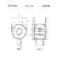
- FIG. 1 is a cross-sectional view through a circular-cylindrical resonator in a preferred embodiment of the invention.
- FIG. 2 is a longitudinal section along the line AA of the microwave arrangement of FIG. 1.
- FIG. 1 shows a microwave arrangement 1 which can be used specifically for the continuous heating of materials 14, such as yarns, threads of, for example, wool or cotton, paper, textile fabrics, film material, tapes, etc.
- microwaves are used for heating, drying or curing these materials.
- the microwave arrangement 1 comprises a cylindrical resonator 2 which, in this embodiment is circular-cylindrical.
- the shape of the cylindrical resonator 2 is, however, not limited in any way to the circular-cylindrical form. Any shape of cylindrical resonator can be used, such as elliptically or coaxially formed resonators.
- the resonator 2 is of such dimensions that at an operating frequency it can be predominantly excited in a given mode, as a result of which field concentrations are generated in the resonator 2.
- an aperture 3 is provided in the cylinder wall 4, which is coupled to a microwave source, not shown, for example a magnetron, via a partly shown waveguide 5.
- the microwave arrangement 1 shown in FIG. 1 is most suitable for heating wire or strip materials 14, which are characterized by their shape and small bulk, as will be described in greater detail below.
- the material 14 is passed into the resonator 2 via an aperture 6 provided in the cylinder wall 4 and is removed from the resonator via a similar aperture 7.
- the size of the apertures 6 and 7 are such that they can radiate little energy. The reason for this is that on the one hand these radiation losses reduce the efficiency and on the other hand that the standards imposed by the authorities must be satisfied, as these losses may cause radiation risks near the resonator 2.
- microwave losses such as dielectric, magnetic and/or conduction losses. More specifically, when the microwave arrangement 1 is used for drying, for example to heat a substance such as water present in or on the material 14, the heat produced by the microwave losses in the material 14 and/or the substance is used for evaporating this substance.
- a general problem with microwave arrangements 1 when used for heating material 14 is how to apply as much as possible of the energy applied to the resonator 2, to the material 14.
- An important standard for the properties of the microwave arrangement 1 is its "efficiency".
- the efficiency expresses the ratio between the energy absorbed by the material 14 to the energy applied to the resonator. Particularly when materials 14 having a small volume per unit of length, for example wire, tube, tape or strip-shaped materials, are used, the efficiency is low.
- transport means for example 8, are provided in the resonator 2 for conveying the material 14 through the resonator 2 via a curved path, for example 13, shown in FIG. 1 by means of a dotted line, and the resonator 2 is so dimensioned, in a manner yet to be described, and is so excited that field concentrations occur in the region of the curved path 13.
- a curved path is to be understood to mean one which does not constitute the shortest path between the apertures 6 and 7.
- a reel 8 is shown as the transport means, and comprises the rods 8-1 to 8-5 shown in FIG. 2.
- the invention is however not limited to the transport means shown in the Figures, but these means may have any shape.
- the transport means may comprise a cylindrical drum in the form of a cage or a reel 8.
- the drum may have a closed or an open surface structure.
- the open surface of the drum may, for example, have a lattice structure formed by holes, slots etc.
- the reel 8 may have an arbitrary number of rods, which rods may have any arbitrary cross-section, for example round, flat or polygonal and may optionally rotate separately, driven or not driven. So as to limit the losses in the transport means, they should preferably be formed from low-microwave loss materials, such as Teflon (Registered Trade Mark).
- the microwave arrangement 1 is in principle suitable for excitation in a single mode or in a combination of modes, such as TE, TM and TEM-modes. More specifically, the resonator 2 shown in this embodiment may be dimensioned for resonating predominantly in a TE 01n mode (where n is an integer).
- a result of exciting the resonator in this last mode, at a given value of n, is that the field concentrations are located on a circular-cylindrical mantle surface 12, represented by a dashed line, along which the material 14 can be fed through, for example, the reel 8.
- a cylindrical surface must be understood to mean the surface obtained by displacing a straight line parallel to itself along a closed curve.
- the material 14 may, for example, be passed along a curved path 13, as shown in FIG. 1 by means of a dotted line. Compared to the shortest connection from aperture 6 to aperture 7, the curved path 13 is longer, as a result of which a larger volume of the material 14 is present in the resonator 2. For the same concentration of the field per unit of path length, more energy can then be absorbed, which improves the efficiency.
- the transport means shown in the Figures comprise a reel 8, it is possible to wind the material 14 a plurality of times around the reel 8. This increases the path length to a very large extent and causes a corresponding increase in material in the resonator 2, without the necessity of increasing the dimensions of the resonator 2. The result is a simple and very compact high-efficiency microwave arrangement 1.
- the period in which the material stays in the resonator and the feed-through rate can be controlled independently of each other. More specifically, it is possible to accomplish an increase in the feed-through rate of the material 14, the staying period remaining, for example, the same, by passing the material 14 via more turns 14 through, for example, a helical path along the mantle surface 12.
- FIG. 2 illustrates how the material 14 can be passed along the reel 8 through, for example, five turns 15.
- the transport means 8 with mechanical guide means 16, such as a comb shown in the Figures, or by providing grooves, projections etc.
- the material 14 is passed along a helical path, generally via several turns 15, through the resonator 2.
- This helical path may have a pitch, which must be understood to mean the displacement of the material 14 per turn measured along the longitudinal axis of the resonator 2.
- the pitch of the path described by the material 14 through the resonator 2 can be determined with the aid of the mechanical guide means 16.
- the extent of heat dissipation by the material 14 during the period the material stays in the resonator 2 can be controlled by adjusting the pitch of the path. This makes it possible to prevent the above-mentioned damage to the material.
- the grooves, the projections or the teeth of the comb be capable of being adjusted and positioned for each turn 15, providing the possibility of obtaining the variable pitch.
- the degree of heat dissipation separately, and consequently accurately, for each turn 15.
- the transport means are in the form of a reel 8 or a circular-cylindrical drum, not shown, with a smooth surface
- a pitch angle is obtained in the resonator 2 at which, measured relative to the longitudinal axis of the resonator 2, the matrial travels through the resonator 2. This angle is a measure of the pitch.
- the resonator 2 can, for example, be dimensioned to resonate at the operating frequency in the TE 011 mode.
- the electric field lines are concentric circles. That is to say, the electric field lines associated with this mode do not intersect the wall material.
- breakdown usually occurs at the wall of the resonator 2, more specifically in the region where the field lines emerge from the wall. Breakdown occurs, inter alia, due to the roughness of the wall material, which requires the surface of the wall material to be finished to a certain smoothness.
- the electric field lines do not intersect wall material, the risk of breakdown is reduced, so that the surface finish of the wall material may be less smooth and consequently may be effected at lower cost.
- the power applied by the microwave source to the resonator 2 can be reduced without affecting the proper operation. This reduces the electric field strength in the resonator 2, and consequently the risk of breakdown.
- the resonator 2 will resonate in the TE 011 mode, a maximum electrical field strength then occurring on a circular-cylindrical surface, the diameter of which is equal to 0.48 times the inside diameter of the resonator 2, which can easily be demonstrated theoretically.
- the mantle surface 12 preferably coincides with this circular-cylindrical surface.
- the absolute maximum of the field concentration depends inter alia also on the ratio between the inside diameter and the axial length of the resonator 2, and is obtained at a ratio of substantially 1.44.
- the maximum efficiency is also obtained in that the electrical field lines, more specifically on excitation in the TE 01n mode, and the magnetic field lines, more specifically on excitation in the TM 01n mode, approximately coincide with the longitudinal direction of the material 14 wound on the reel 8. As a result thereof, the coupling of the material 14 to the respective fields is at its maximum. Because of this very good coupling, the quantity of energy absorbed from the field by the material 14 will be at its optimum and consequently also the heating.
- the shape of the apertures 6 and 7 can be adapted to the shape of the materials 14.
- the apertures 6 and 7 may, for example, be narrow slots which guide this material 14 without deformation through the wall of the resonator 2.
- the longitudinal axis of each of the slots should preferably be located so that it does not substantially intersect current lines.
- Identical end plates 9 are preferably provided at both ends of the resonator 2 in such a manner that they do not touch the cylindrical wall 4. This creates concentric annular apertures 10 at both end faces.
- the shape and location of the apertures 10 do not influence the excitation of TE 01n modes as they do not constitute an interruption in the wall currents.
- the wall currents associated with these other modes are interrupted by the apertures 10.
- the excitation in the resonator 2 of these unwanted other modes, when the TE 01n mode is used, is suppressed.
- the two end plates 9 are used as end plates of the reel 8 and the reel 8 is provided in such a way that it is capable of rotation about the longitudinal axis of the resonator 2, it is possible to realize the conveyance of the material 14 through the resonator 2 in a simple way by driving the reel.
- means 11 can be connected in a simple way to the apertures 10 for supplying and discharging the air required for the drying process.
- the apertures 10 are provided in a region at the end faces near the cylinder wall 4, the air flows along the cylinder wall 4 after it has entered the resonator 2.
- the cylinder wall 4 is heated. This heat is discharged by the air flowing along it. As hot air can hold more moisture than cold air, the drying properties of a microwave arrangement when used more specifically as a drying device will be improved. Compared with the choice of a drum, choosing a reel 8 has the advantage that a larger portion of the material surface area conveyed through the resonator 2 is exposed to the air, causing the material to be dried more uniformly and faster.
Landscapes
- Physics & Mathematics (AREA)
- Electromagnetism (AREA)
- Constitution Of High-Frequency Heating (AREA)
- Drying Of Solid Materials (AREA)
Applications Claiming Priority (2)
| Application Number | Priority Date | Filing Date | Title |
|---|---|---|---|
| NL8402999 | 1984-10-02 | ||
| NL8402999A NL8402999A (nl) | 1984-10-02 | 1984-10-02 | Mikrogolfinrichting voor het verhitten van materiaal. |
Publications (1)
| Publication Number | Publication Date |
|---|---|
| US4626640A true US4626640A (en) | 1986-12-02 |
Family
ID=19844546
Family Applications (1)
| Application Number | Title | Priority Date | Filing Date |
|---|---|---|---|
| US06/779,770 Expired - Fee Related US4626640A (en) | 1984-10-02 | 1985-09-25 | Microwave arrangement for heating material |
Country Status (7)
| Country | Link |
|---|---|
| US (1) | US4626640A (de) |
| EP (1) | EP0179512B1 (de) |
| JP (1) | JPH0634388B2 (de) |
| AU (1) | AU581449B2 (de) |
| CA (1) | CA1243082A (de) |
| DE (1) | DE3584069D1 (de) |
| NL (1) | NL8402999A (de) |
Cited By (7)
| Publication number | Priority date | Publication date | Assignee | Title |
|---|---|---|---|---|
| US4760230A (en) * | 1985-09-27 | 1988-07-26 | Stiftelsen Institutet For Mikrovagsteknik Vid Tekniska Hogskolan I Stockholm | Method and an apparatus for heating glass tubes |
| US5008978A (en) * | 1988-06-03 | 1991-04-23 | Maschinenfabrik Rieter Ag | Apparatus for treating cotton contaminated with honeydew |
| US5341576A (en) * | 1990-06-29 | 1994-08-30 | Matsui Manufacturing Co., Ltd. | Method and apparatus for drying granular materials |
| EP1261237A1 (de) * | 2001-04-30 | 2002-11-27 | Hewlett-Packard Company | Trocknungsvorrichtung |
| US20070079522A1 (en) * | 2005-09-22 | 2007-04-12 | Eastman Chemical Company | Microwave reactor having a slotted array waveguide |
| US20070079523A1 (en) * | 2005-09-22 | 2007-04-12 | Eastman Chemical Company | Microwave reactor having a slotted array waveguide coupled to a waveguide bend |
| US9282594B2 (en) | 2010-12-23 | 2016-03-08 | Eastman Chemical Company | Wood heater with enhanced microwave launching system |
Families Citing this family (1)
| Publication number | Priority date | Publication date | Assignee | Title |
|---|---|---|---|---|
| FR2874473B1 (fr) * | 2004-08-19 | 2008-10-10 | Michel Boulard | Procede et dispositif pour le traitement thermique d'un materiau souple |
Citations (7)
| Publication number | Priority date | Publication date | Assignee | Title |
|---|---|---|---|---|
| US2483933A (en) * | 1947-10-15 | 1949-10-04 | Gen Electric | Ultra high frequency dielectric heater |
| US3426439A (en) * | 1967-02-16 | 1969-02-11 | Houston Fearless Corp | Microwave drying system |
| US3461261A (en) * | 1966-10-31 | 1969-08-12 | Du Pont | Heating apparatus |
| US3597567A (en) * | 1969-09-24 | 1971-08-03 | Ray M Johnson | Microwave applicator for heating continuous web |
| US3739130A (en) * | 1972-05-25 | 1973-06-12 | Guardian Packaging Corp | Multi cavity microwave applicator |
| US3740515A (en) * | 1970-11-27 | 1973-06-19 | Canadian Patents Dev | Microwave heating apparatus |
| US3952421A (en) * | 1974-10-18 | 1976-04-27 | Chemetron Corporation | Dielectric heating arrangement for drying a continuously moving web of material |
Family Cites Families (7)
| Publication number | Priority date | Publication date | Assignee | Title |
|---|---|---|---|---|
| FR972524A (fr) * | 1947-10-15 | 1951-01-31 | Thomson Houston Comp Francaise | Appareil de chauffage par pertes diélectriques utilisable en ultra haute fréquence |
| DE902421C (de) * | 1951-12-23 | 1954-01-21 | Albert Ag Chem Werke | Verfahren zur kontinuierlichen oder diskontinuierlichen dielektrischen Vortrocknung und Vorwaermung von kunstharzimpraegnierten Bahnen fuer die Herstellung von Schichtpressstoffen |
| JPS446948Y1 (de) * | 1966-09-16 | 1969-03-14 | ||
| GB1374238A (en) * | 1970-10-13 | 1974-11-20 | Rotax Ltd | Method of and apparatus for reducing the moisture content in fibrous sheet material |
| LU62048A1 (de) * | 1970-11-12 | 1972-07-26 | ||
| JPS5143945U (de) * | 1974-09-28 | 1976-03-31 | ||
| US4458128A (en) * | 1983-03-28 | 1984-07-03 | Raytheon Company | Microwave sheet rubber curing |
-
1984
- 1984-10-02 NL NL8402999A patent/NL8402999A/nl not_active Application Discontinuation
-
1985
- 1985-09-25 US US06/779,770 patent/US4626640A/en not_active Expired - Fee Related
- 1985-09-26 CA CA000491594A patent/CA1243082A/en not_active Expired
- 1985-09-27 EP EP85201560A patent/EP0179512B1/de not_active Expired
- 1985-09-27 DE DE8585201560T patent/DE3584069D1/de not_active Expired - Lifetime
- 1985-10-01 AU AU48160/85A patent/AU581449B2/en not_active Ceased
- 1985-10-02 JP JP60218140A patent/JPH0634388B2/ja not_active Expired - Lifetime
Patent Citations (7)
| Publication number | Priority date | Publication date | Assignee | Title |
|---|---|---|---|---|
| US2483933A (en) * | 1947-10-15 | 1949-10-04 | Gen Electric | Ultra high frequency dielectric heater |
| US3461261A (en) * | 1966-10-31 | 1969-08-12 | Du Pont | Heating apparatus |
| US3426439A (en) * | 1967-02-16 | 1969-02-11 | Houston Fearless Corp | Microwave drying system |
| US3597567A (en) * | 1969-09-24 | 1971-08-03 | Ray M Johnson | Microwave applicator for heating continuous web |
| US3740515A (en) * | 1970-11-27 | 1973-06-19 | Canadian Patents Dev | Microwave heating apparatus |
| US3739130A (en) * | 1972-05-25 | 1973-06-12 | Guardian Packaging Corp | Multi cavity microwave applicator |
| US3952421A (en) * | 1974-10-18 | 1976-04-27 | Chemetron Corporation | Dielectric heating arrangement for drying a continuously moving web of material |
Cited By (11)
| Publication number | Priority date | Publication date | Assignee | Title |
|---|---|---|---|---|
| US4760230A (en) * | 1985-09-27 | 1988-07-26 | Stiftelsen Institutet For Mikrovagsteknik Vid Tekniska Hogskolan I Stockholm | Method and an apparatus for heating glass tubes |
| US5008978A (en) * | 1988-06-03 | 1991-04-23 | Maschinenfabrik Rieter Ag | Apparatus for treating cotton contaminated with honeydew |
| US5048156A (en) * | 1988-06-03 | 1991-09-17 | Maschinenfabrik Rieter, Ag | Method of treating cotton contaminated with honeydew |
| US5341576A (en) * | 1990-06-29 | 1994-08-30 | Matsui Manufacturing Co., Ltd. | Method and apparatus for drying granular materials |
| EP1261237A1 (de) * | 2001-04-30 | 2002-11-27 | Hewlett-Packard Company | Trocknungsvorrichtung |
| US20070079522A1 (en) * | 2005-09-22 | 2007-04-12 | Eastman Chemical Company | Microwave reactor having a slotted array waveguide |
| US20070079523A1 (en) * | 2005-09-22 | 2007-04-12 | Eastman Chemical Company | Microwave reactor having a slotted array waveguide coupled to a waveguide bend |
| US8299408B2 (en) | 2005-09-22 | 2012-10-30 | Eastman Chemical Company | Microwave reactor having a slotted array waveguide coupled to a waveguide bend |
| US8487223B2 (en) | 2005-09-22 | 2013-07-16 | Eastman Chemical Company | Microwave reactor having a slotted array waveguide |
| US9282594B2 (en) | 2010-12-23 | 2016-03-08 | Eastman Chemical Company | Wood heater with enhanced microwave launching system |
| US9456473B2 (en) | 2010-12-23 | 2016-09-27 | Eastman Chemical Company | Dual vessel chemical modification and heating of wood with optional vapor |
Also Published As
| Publication number | Publication date |
|---|---|
| NL8402999A (nl) | 1986-05-01 |
| CA1243082A (en) | 1988-10-11 |
| JPS6188490A (ja) | 1986-05-06 |
| AU4816085A (en) | 1986-04-10 |
| EP0179512A1 (de) | 1986-04-30 |
| AU581449B2 (en) | 1989-02-23 |
| DE3584069D1 (de) | 1991-10-17 |
| JPH0634388B2 (ja) | 1994-05-02 |
| EP0179512B1 (de) | 1991-09-11 |
Similar Documents
| Publication | Publication Date | Title |
|---|---|---|
| US3461261A (en) | Heating apparatus | |
| US4626640A (en) | Microwave arrangement for heating material | |
| US6323470B2 (en) | Method for rapid drying of coated materials with close capture of vapors | |
| US3560694A (en) | Microwave applicator employing flat multimode cavity for treating webs | |
| US4476363A (en) | Method and device for heating by microwave energy | |
| US3851132A (en) | Parallel plate microwave applicator | |
| US5400524A (en) | Installation for continuously drying, dehydrating or microwave baking of granular or powdered products | |
| CA2401353A1 (en) | Microwave heating apparatus | |
| US8674275B2 (en) | Method of fabricating a honeycomb structure using microwaves | |
| US3705283A (en) | Microwave applicator employing a broadside slot radiator | |
| US3557334A (en) | Method and apparatus for regulating heating in a microwave resonant cavity | |
| US5278375A (en) | Microwave applicator device for the treatment of sheet or lap products | |
| US3764768A (en) | Microwave applicator employing a broadside slot radiator | |
| US3673370A (en) | Microwave applicator system with cylindrical resonant cavity | |
| US3622732A (en) | Microwave applicator with distributed feed to a resonator | |
| US4689459A (en) | Variable Q microwave applicator and method | |
| KR20010021935A (ko) | 표면파 플라즈마를 이용한 기체 여기 장치 | |
| US3597566A (en) | Resonant cavity microwave applicator | |
| US6072167A (en) | Enhanced uniformity in a length independent microwave applicator | |
| US4780585A (en) | Method and device for the thermal treatment of a conductor element at least partially constituted by a conducting material | |
| GB2053629A (en) | Process and Device for the Heat Treatment of Filiform Elements | |
| JP2010168684A (ja) | マイクロ波延伸装置 | |
| US3463894A (en) | Microwave drying system using phase shifters | |
| US4011641A (en) | Jacketed roller for synthetic yarn spinning apparatus | |
| VanKoughnett | A microwave applicator for filamentary materials |
Legal Events
| Date | Code | Title | Description |
|---|---|---|---|
| AS | Assignment |
Owner name: U.S. PHILIPS CORPORATION, 100 EAST 42ND STREET, NE Free format text: ASSIGNMENT OF ASSIGNORS INTEREST.;ASSIGNOR:VAN DER HEIJDEN, BERNARDUS F.;REEL/FRAME:004482/0082 Effective date: 19851105 |
|
| FEPP | Fee payment procedure |
Free format text: PAYOR NUMBER ASSIGNED (ORIGINAL EVENT CODE: ASPN); ENTITY STATUS OF PATENT OWNER: LARGE ENTITY |
|
| FPAY | Fee payment |
Year of fee payment: 4 |
|
| FPAY | Fee payment |
Year of fee payment: 8 |
|
| REMI | Maintenance fee reminder mailed | ||
| LAPS | Lapse for failure to pay maintenance fees | ||
| FP | Lapsed due to failure to pay maintenance fee |
Effective date: 19981202 |
|
| STCH | Information on status: patent discontinuation |
Free format text: PATENT EXPIRED DUE TO NONPAYMENT OF MAINTENANCE FEES UNDER 37 CFR 1.362 |