US462615A - Cash-register - Google Patents
Cash-register Download PDFInfo
- Publication number
- US462615A US462615A US462615DA US462615A US 462615 A US462615 A US 462615A US 462615D A US462615D A US 462615DA US 462615 A US462615 A US 462615A
- Authority
- US
- United States
- Prior art keywords
- cash
- plate
- drawer
- key
- register
- Prior art date
- Legal status (The legal status is an assumption and is not a legal conclusion. Google has not performed a legal analysis and makes no representation as to the accuracy of the status listed.)
- Expired - Lifetime
Links
- 230000000994 depressed Effects 0.000 description 24
- 239000011521 glass Substances 0.000 description 14
- 238000005192 partition Methods 0.000 description 12
- 230000000881 depressing Effects 0.000 description 10
- 239000000203 mixture Substances 0.000 description 10
- 238000010276 construction Methods 0.000 description 8
- 230000000875 corresponding Effects 0.000 description 8
- UFULAYFCSOUIOV-UHFFFAOYSA-N Cysteamine Chemical compound NCCS UFULAYFCSOUIOV-UHFFFAOYSA-N 0.000 description 6
- 230000003028 elevating Effects 0.000 description 4
- 241000252073 Anguilliformes Species 0.000 description 2
- 102100000730 CKM Human genes 0.000 description 2
- 101710024062 CKM Proteins 0.000 description 2
- 241000234435 Lilium Species 0.000 description 2
- 239000000463 material Substances 0.000 description 2
- 230000000284 resting Effects 0.000 description 2
- 238000004804 winding Methods 0.000 description 2
Images


Classifications
-
- G—PHYSICS
- G07—CHECKING-DEVICES
- G07D—HANDLING OF COINS OR VALUABLE PAPERS, e.g. TESTING, SORTING BY DENOMINATIONS, COUNTING, DISPENSING, CHANGING OR DEPOSITING
- G07D9/00—Counting coins; Handling of coins not provided for in the other groups of this subclass
- G07D9/06—Devices for stacking or otherwise arranging coins on a support, e.g. apertured plate for use in counting coins
Definitions
- My invention relates to improvements in cash-registers for stores and other places of that class in which the amount of a sale is displayed and registered and a drawer opened and an alarm sounded by depressing an opposite key.
- One of the objects of my invention is to furnish a register in which the till or cash-drawer is inaccessible, except to the parties who are entitled to handle the receipts, a separate and independent drawer being provided for the purpose of making' change.
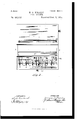
- Figure 1 is a perspective View ot' a cash-register constructedin accordance with my invention, the till or cash-drawer being shown partly open.
- Fig. 2 is a plan view of the same, parts of the casing being removed to .show the interior construction.
- Fig. 3 is a central longitudinal sectional view.
- Fig. 4C is a horizontal section on the line y/ y,
- Fig. Fig. 5 is a perspective view ot' the mechanism for operating the indicating or registering tapes.
- Fig. 6 is a detail perspective view ot the means of operating the display-plates.
- Fig. 7 is a detail perspective View of the cash-holding plates.
- Figs. S and S) are detail sectional views of one of the ratchet-wheels operated by the indicating-keys.
- Fig. 10 is a perspective view of the cover through which the tapes can beinspected.
- the reference-nu meral l designates the front of the casing, 2 the bottom, the back wall, and 5 5 the sides, which are approximately triangular in shape or formed with inclined top edges.
- This drawer is formed with a number ot' compartments or cash-receptacles 7 to receive coin and with a receptacle S at the top for the reception oi' bills or currency, which are deposited in a manner hereinafter described.
- a changedrawer 9 having an angular plate 10 at the top of its rear wall, which engages with the end of a pivoted catch 12, mounted upon a pintle k1 3, extending across a slot 1t in the plate 15, which lies above and forms a cover for the drawer E) when the latter is closed.
- This catch is also formed or provided with a forwardly-projecting arm 16, with which engage two transverse bars 17, pivoted to short posts 18, secured to the plate 15, so that as a key is depressed to register a sale its lower end willy bear upon said bars, as shown by the dotted lilies, Fig.
- the changedrawer 9 is provided with a rearwardly-extending arm 22,having its free end bent upwardly at a right angle, so as to engage with IOO a pivoted hammer-arm 23, having a head 24, and trip the same and sound an alarm upon the loell or gong when'the drawer is opened.
- a series of spring-catches 37 Secured to the plate or wall l5 is a series of spring-catches 37, the free ends of which engage with the ratchet-wheels30, so Vas to prevent any backward movement thereof, and resting upon these catches is a transverse bar 3S, providedv with a pin 33 and knob 39, projecting through lthe inclined cover 2G.
- a transverse bar 3S providedv with a pin 33 and knob 39, projecting through lthe inclined cover 2G.
- an inclined transverse partition 40 In rear of and above the spring-barrels 35 is an inclined transverse partition 40, leading to the cash-drawer, and above this partition 40 is a transverse pivoted plate 42, having lugs 43 at each end, which are journaled in the sides of the casing. A short. distance in front of this plate 42 is a fixed plate 44, havingl a double glass front 45. In the partition 40, just back of plate 44,is a transverse opening 46, communicating with the inclined plate 40.
- the numeral4l designates a cover secured to the casing, provided with a series of openings marked, respectively, 5, l0, 25, 50, and 100 to receive coins of these denominations.
- the partition 40 is a vertical partition 48 and a transverse partition 49. These partitions, in connection with top 5l, form a chamber, in which is located a pivoted plate 52, similar to plate 42, and in front thereof is a transverse plate 53 and a glass front 54.
- the top 5l is provided with one or more slots 55, through which bills or currency can be introduced into the space between plate 52 and the glass front 54, so that they will rest upon said plate and be easily discerned through said front. In asimilar manner the coins introduced through the openings in plate 4l will rest against plate 42, so that they will be in full sight of the party making a purchase.
- ratchet-wheels 5S Fixed to shaft 32 and abutting against the ratchet-wheels 30 is a series of ratchet-wheels 5S, (one for each wheel 30,) rthe ratchets of which are engaged by a spring-pawl 501 on each wheel 30, so that as an indicating-key is depressed and a ratchet-wheel 30 accordingly actuated the wheels 58 will be correspondingly actuated, rotating shaft 32, which carries a cog-wheel 59, meshing with a similar wheel 59, fixed to a transverse shaft GO, journaled in the sides of the casing.
- this shaft GO Upon one end of this shaft GO are a series of radiating arms 6l, (four being shown in this instanee,) which engage witha tripping-lever G2 when the shaft is actuated, said tripping-lever being pivoted to an arm 63, secured to plate 42', so that the latter will be turned so as to uncover the coin-openings and allow the coin to drop into the cashdrawer, the bill plate 52 being ⁇ - also turned through the connecting rod or bar 5G.
- the object of the double glass front 45 is that a display-plate may be projected upwardly therebetween, indicating the amount of a sale as a key is depressed.
- the numeral 64 denotes a rod or. bar, which is loosely pivoted on the shaft 32, having a forwardlyextending arm G5, which is adapted to be struck by a pin G5 on an indicating-key when depressed.
- Each of these bars also has a rearwardl extending arm GG, pivoted or hinged to an arm GG, provided with a downward extension or lug G7 intermediate of its ends, which is adapted to engage with the up per one of a series of longitudinal grooves 68 in the shaft GO.
- the rear ends of these bars are provided with hinged or pivoted vertical rods G9, carrying at their upper ends display- TOO IIO
- the lug 67 will also engage wit-l1 the grooves 68 in the shaft GO, and thus be prevented from falling down when the key is released, so that the plate 70, displaying the amount of the sale, will remain in its elevated position and in sight until another keyis depressed, when the shaft 60 will be rotated by the cog-wheels 59 and 59fL and connections, disengaging the lug G7 from the groove and allowing it and the plate 70 to drop down.
- the numeral 71 designates a key, the lower end of, which when depressed will strike the arm 16, so as to release the catch 12 and allow the change-drawer to open. This key is used when it is desired to open the drawer without actuating the registering mechanism. yThe operation is as follows: In the beginning of a days work all the tapes carried by the spring-barrels are set'at zero, the cashdrawer locked, and a sufficient amount of change placed in the change-drawer for all ordinary purposes. ready for work. Supposing that a customer makes apurchase amountingto, say,ftycents, and tenders alifty-cent coin in payment thereof.
- the employe depresses the fifty cent key, which will by means of its spring-pawl move the corresponding ratchet-wheel and cause the tape connected with its hub to move from zero to l, thus indicating through the display-opening that one sale to the value of fifty cents has been made.
- the lower end of the key will strike and depress the bars 17, actuating the pivoted lever, releasingthe catch 12,and allowing the changedrawer to be forced open by the springs 19 and sounding an alarm. Vhile these operations are being performed the rod (56 is also tripped by the key, causing the vertical arm carrying the display-plate to be forced upwardly, projecting said plate between the glass fronts, so that the amount indicated thereon will be in full sightof the purchaser.
- the lug G7 will then be raised up and will catch in the grooves' in the shaft GO and'will be held until another key is depressed, indieating a subsequent sale.
- the ratchet-wheel 30 will be rotated or turned a short distance, causing the shaft to be correspondingly turned, and by means of the cog-wheels 59land 59, turning shaft GO, which by means of the radial arms 61 will trip the lever 12 and cause the plates 42 and 52 to be turned on their pivots, so that any cash which The apparatus is nowv niayhavebeen deposited previouslyis dropped into the cash-drawer.
Description
(No Model.) 7 Sheets-Sheet 1. H. A. BIERLEY.
CASH REGISTER.
110. 462,615. Patented 110V. s, 1891.
1. 'm 1 -L--fm/VEWZUQ;
./Qzerley,
we uname. mms co., mom-l mw wsrmoww, n c.
(No Model.)
7 Sheets-Sheet 2. H. A. BIERLEY.
CASH REGISTER.
Patented Nov. 3,1891.
l O 60g l .5 f 2f l z/ 6 .3 2, 53 a 1 ax O z/ 5038 so WIZJVESSES: i5 @Vf f IME/W02.; jv/'ew y Bz/ewey, l l
.71 liormyu;
(No Model.) 7 Sheets-Sheet 3. H. A. BIERLEY.
CASH REGISTER. No. 462,615. Patented Nov.3,1`891.
me wanms rma-ns cn., wom-uwe., wAsmucmN. u. c.
(No Model.) 7 Sheets-Sheet 4.
H. A. BIERLBY. CASH REGISTER.
No. 462,615. Patented N0v.3,1891.
(No Model.) 7 Sheets-Sheet 5.
H. A. BIERLEY. CASH REGISTER.
Na/162,615. Patented N0v.3|,1891.
we. noms vnr. nnnnnnnnnnnnnnnnnnnnnnnnnnnnnnn n.
(No Modem l 7 sheets-sheen 6. H. A. BIERLEY. CASH REGISTER.
110.462,615. Patented NOV.3,1891.
IME/W02:
y, /I M @ZW/6 :Blarney/LS.
7 Sheets-Sheet 7.
(No Model.)A
H. A. BIERLBY.
. CASH REGISTER., No; 462;61'5'`" :Patented Nov. s, 1891.
C VZ/VESS S. @Mz CKMM m nnnnnnnnn mens nu., pum-umu., msmmN. n. c.
UNITED STATES PATENT OEEICE.
' HENRY A. BIERLEY, OF LEXINGTON, KEN"UCK'Y.
CASH-REGISTER.
SPECIFICATION forming part of Letters Patent No. 462,615, dated INovember 3, 1891.
Application filed July l0, 1891. Serial No. 399,032. (No model.)
To a/ZZ whom t may concern:
Be it known that I, HENRY A. BIERLEY, a citizen of the United States, and a resident of Lexington, in the county ot Fayette and State of Kentucky, have invented certain new and useful Improvements in Cash-Registers; and I do hereby declare that the following is a full,clear, and exact description ot the invention, which will enable others skilled in the art to which it appertains to make and use the same, reference being had to the accompanying drawings, which form a part ol' this specification.
My invention relates to improvements in cash-registers for stores and other places of that class in which the amount of a sale is displayed and registered and a drawer opened and an alarm sounded by depressing an opposite key.
As now generally constructed, cash-registers in which the alnount of a sale is registered and indicated by depressing a key the cash-drawer is opened and the amount ofthe sale placed therein, the proper change, when necessary, being taken from said drawer and handed to the customer or person making a purchase. This is a serious objection, in that f the till or cash-drawer and its contents are accessible to the employs of the store.
One of the objects of my invention, as before stated, is to furnish a register in which the till or cash-drawer is inaccessible, except to the parties who are entitled to handle the receipts, a separate and independent drawer being provided for the purpose of making' change.
There are other advantages with respect to simplicity of construction and eticiency in operation which will be apparent to those skilled in the art to which the invention pertains.
The invention consists in the novel construction and combination of parts hereinafter fully described and claimed.
In the accompanying drawings, Figure 1 is a perspective View ot' a cash-register constructedin accordance with my invention, the till or cash-drawer being shown partly open. Fig. 2 is a plan view of the same, parts of the casing being removed to .show the interior construction. Fig. 3 is a central longitudinal sectional view. Fig. 4C is a horizontal section on the line y/ y, Fig. Fig. 5 is a perspective view ot' the mechanism for operating the indicating or registering tapes. Fig. 6 is a detail perspective view ot the means of operating the display-plates. Fig. 7 is a detail perspective View of the cash-holding plates. Figs. S and S) are detail sectional views of one of the ratchet-wheels operated by the indicating-keys. Fig. 10 is a perspective view of the cover through which the tapes can beinspected.
In the said drawings, the reference-nu meral l designates the front of the casing, 2 the bottom, the back wall, and 5 5 the sides, which are approximately triangular in shape or formed with inclined top edges.
In the rear of the easing is located the cashdrawer or till G, provided with a lock, so that its contents are inaccessible, except to those entitled to receive the same. This draweris formed with a number ot' compartments or cash-receptacles 7 to receive coin and with a receptacle S at the top for the reception oi' bills or currency, which are deposited in a manner hereinafter described.
In the front ot the casing is a changedrawer 9, having an angular plate 10 at the top of its rear wall, which engages with the end of a pivoted catch 12, mounted upon a pintle k1 3, extending across a slot 1t in the plate 15, which lies above and forms a cover for the drawer E) when the latter is closed. This catch is also formed or provided with a forwardly-projecting arm 16, with which engage two transverse bars 17, pivoted to short posts 18, secured to the plate 15, so that as a key is depressed to register a sale its lower end willy bear upon said bars, as shown by the dotted lilies, Fig. 5, depressing the arm 16 and releasing the catch 12, allowing the drawer to be forced open by means of the springs 19, secured to a plate 2U in rear of the cashdrawer. A spring 2l is located intermediate of the arm 16 and plate 15, the tendency ot' which is to elevate said arm and correspond` ingly depress the catch 1.2, so that it will engage with plate 10. The bottom ot' the changedrawer 9 is provided with a rearwardly-extending arm 22,having its free end bent upwardly at a right angle, so as to engage with IOO a pivoted hammer-arm 23, having a head 24, and trip the same and sound an alarm upon the loell or gong when'the drawer is opened.
Projecting through holes or apertures in an inclined plat-e or cover 26, located above the plate or wall 15,is a series of registering-keys 27,which are provided at their upper ends with disks 2S, having numbers indicating` different amounts, as is usual, said plate 26 having an opening 25, through which the registering-tapes can be inspected in this description of apparatus. Near their lower ends these keys are provided with sprillg-pawls 29,
which engage with ratchet-wheels 30, having hubs 3l loose upon a transverse shaft 32, so as to rotate thereon when the keys are depressed. The keys are provided with coiled springs 27L to return them to normal position. Secured to the hubs 3l are tapes 33 of flexible material, the other ends of which are connected to spring-barrels having cases 35 secured in slots in a vertical plate 3G, similar to ordinary spring tape-measures. 'These tapes or strips are provided on one of their sides with numbers arranged consecutively thereon from zero upward. There will be one of these spring-barrels and tapes for each registering-key, so that as said keys are depressed, indicating the amount of a sale,they will engage With their corresponding ratchet-wheels winding the tapes connectedtherewith upon their respective drums. rlhe relative arrangement and construction of these keys, ratchetwheels, and tapes are such that each depression of a key causes its corresponding tape to be moved forward a distance equal to one number thereon.
Secured to the plate or wall l5 is a series of spring-catches 37, the free ends of which engage with the ratchet-wheels30, so Vas to prevent any backward movement thereof, and resting upon these catches is a transverse bar 3S, providedv with a pin 33 and knob 39, projecting through lthe inclined cover 2G. By depressing this knob and bar the catches 37 will be disengaged from the ratchets in Wh eels 30, allowing` the tapes to be rewound upon their spring-barrel. This is done before the beginning. of a days work, so that all the tapes will indicate zero.
In rear of and above the spring-barrels 35 is an inclined transverse partition 40, leading to the cash-drawer, and above this partition 40 is a transverse pivoted plate 42, having lugs 43 at each end, which are journaled in the sides of the casing. A short. distance in front of this plate 42 is a fixed plate 44, havingl a double glass front 45. In the partition 40, just back of plate 44,is a transverse opening 46, communicating with the inclined plate 40.
The numeral4l designates a cover secured to the casing, provided with a series of openings marked, respectively, 5, l0, 25, 50, and 100 to receive coins of these denominations.
`Above the partition 40 is a vertical partition 48 and a transverse partition 49. These partitions, in connection with top 5l, form a chamber, in which is located a pivoted plate 52, similar to plate 42, and in front thereof is a transverse plate 53 and a glass front 54. The top 5l is provided with one or more slots 55, through which bills or currency can be introduced into the space between plate 52 and the glass front 54, so that they will rest upon said plate and be easily discerned through said front. In asimilar manner the coins introduced through the openings in plate 4l will rest against plate 42, so that they will be in full sight of the party making a purchase. Vhen these plates 42 and 52 are turned upon their pivots, so aste uncover the case leading to the cash-drawer, as hereinafter set forth, by the depression of a registering-key as another sale is indicated, the coins or bills will fall through said openings into the cashdrawer. The plates 42 and 52 arcconnected together by means of a rod or bar 56,'so as to move in unison, and are each provided with coiled springs 57, secured thereto and to the sides of the casing, the function of whichis to return the plates to normal position after having been actuated to deposit the coins or bills in the cash-drawer.
I will new proceed to describe the means for actuating said plates. Fixed to shaft 32 and abutting against the ratchet-wheels 30 is a series of ratchet-wheels 5S, (one for each wheel 30,) rthe ratchets of which are engaged by a spring-pawl 501 on each wheel 30, so that as an indicating-key is depressed and a ratchet-wheel 30 accordingly actuated the wheels 58 will be correspondingly actuated, rotating shaft 32, which carries a cog-wheel 59, meshing with a similar wheel 59, fixed to a transverse shaft GO, journaled in the sides of the casing. Upon one end of this shaft GO are a series of radiating arms 6l, (four being shown in this instanee,) which engage witha tripping-lever G2 when the shaft is actuated, said tripping-lever being pivoted to an arm 63, secured to plate 42', so that the latter will be turned so as to uncover the coin-openings and allow the coin to drop into the cashdrawer, the bill plate 52 being`- also turned through the connecting rod or bar 5G.
The object of the double glass front 45 is that a display-plate may be projected upwardly therebetween, indicating the amount of a sale as a key is depressed. This Iaccoinplish by the following means: The numeral 64 denotes a rod or. bar, which is loosely pivoted on the shaft 32, having a forwardlyextending arm G5, which is adapted to be struck by a pin G5 on an indicating-key when depressed. Each of these bars also has a rearwardl extending arm GG, pivoted or hinged to an arm GG, provided with a downward extension or lug G7 intermediate of its ends, which is adapted to engage with the up per one of a series of longitudinal grooves 68 in the shaft GO. The rear ends of these bars are provided with hinged or pivoted vertical rods G9, carrying at their upper ends display- TOO IIO
The numeral 71 designates a key, the lower end of, which when depressed will strike the arm 16, so as to release the catch 12 and allow the change-drawer to open. This key is used when it is desired to open the drawer without actuating the registering mechanism. yThe operation is as follows: In the beginning of a days work all the tapes carried by the spring-barrels are set'at zero, the cashdrawer locked, and a sufficient amount of change placed in the change-drawer for all ordinary purposes. ready for work. Supposing that a customer makes apurchase amountingto, say,ftycents, and tenders alifty-cent coin in payment thereof. The employe depresses the fifty cent key, which will by means of its spring-pawl move the corresponding ratchet-wheel and cause the tape connected with its hub to move from zero to l, thus indicating through the display-opening that one sale to the value of fifty cents has been made. At the same time the lower end of the key will strike and depress the bars 17, actuating the pivoted lever, releasingthe catch 12,and allowing the changedrawer to be forced open by the springs 19 and sounding an alarm. Vhile these operations are being performed the rod (56 is also tripped by the key, causing the vertical arm carrying the display-plate to be forced upwardly, projecting said plate between the glass fronts, so that the amount indicated thereon will be in full sightof the purchaser. The lug G7 will then be raised up and will catch in the grooves' in the shaft GO and'will be held until another key is depressed, indieating a subsequent sale. At the 'same time the ratchet-wheel 30 will be rotated or turned a short distance, causing the shaft to be correspondingly turned, and by means of the cog-wheels 59land 59, turning shaft GO, which by means of the radial arms 61 will trip the lever 12 and cause the plates 42 and 52 to be turned on their pivots, so that any cash which The apparatus is nowv niayhavebeen deposited previouslyis dropped into the cash-drawer. Upon the pressure on the key being relieved it will resume norma-l position by means of springs, and the plates 4:2 and 52 will also be returned to normal by means ofsprings 57, closing the openings leading to the cash-drawer. The coin received from the purchaser will then be inserted in its proper slot and will fall into the space between the glass fronts 45 and be in plain sight. The display-plate indicating the amount of purchase will remain in sight until a subsequent sale is made andthe appropriate key depressed. This is accomplished by means of the grooved shaft GO, as before set forth. XVhen bills are tendered in payment instead of coins, they are placed in the bill-openings, the operation of the apparatus being otherwise the same. At the close of business the aggregate amount of sales can be ascertained from the indicating-tapes,and the cash in thecash-drawer, plus any change given, must correspond therewith, the change-drawer being credited with the amount in the cash-drawer over and above the sales registered-that is to say, suppose at the beginning of business ten dollars in change is in the change-drawer and during the day sales to the amount of one hundred dollars have been made and change to the amount of five dollars given out, then there will be one hundred and iive dollars in the cash-drawer andlive dollars in the changedrawer,\vliile the tapes will register $100, the amount of sales made, the sum in the cashdrawer always balancing the amount indicated by the tapes plus the cash in the changedrawer. The plate 71, hinged to the casing,
is intended to be locked and the key kept by the proprietor of the store or other person in authority.
Having thus described my invention, what I claim is- 1. In a cash-register, the combination of the casing, the spring-barrels carrying tapes with indicating characters, the transverse shaft carrying loose ratchet-wheels, the hubs connected with said ratchet-wheels, the ratchet-wheels xed on said shaft, the spring-pawls engaging therewith, the indicating-keys having spring-pawls, the transverse shaft, the cog-wheels carried bysaid shafts, the radial arms, the pivoted plates for retaining the cash in sight, and the pivoted arm adapted to be actuated bysaid radial arms, substantially as described.
2. In a cash-register, the combination of the casing, the spring-barrels, the registeringtapes, the transverse shafts 32 and GO, the loose ratchet wheels 30, the fixed ratchetwheels 5S, the indicating-keys, the pawls 20 and 59'), the spring-catches 37, the bar 38, and the pi voted rods 17, substantially as described.
In a cash-register, the combination of the casing, the spring-barrels and tapes, the shafts 32 and GO, the loose ratchet-wheels 30, havings pawls 59", the fixed ratchet-wheels 58, the spring-actuated indicating-keys, the cog- IOO ITO
4L. In a cash-register, the combination of the casing, the shafts and GO, the springbarrels 35,the tapes 33, the ratchet-wheels 30, the hubs 31,1:he pawls 59, the ratchet-wheels 5S, the indicating-keys having pawls 29, the arms 66, pivoted in shaft and having forwardly extending arms G5, the arms 6G, hinged to arms 66, the lugs 67, adapted to engage with grooves in shaft GO, and the vertical bar hinged to arm 66L and Carrying a displayplate, substantially as described.
In testimony that I claim the foregoing as my own I have hereunto affixed my signature in presence of two witnesses.
HENRY A. BIERLEY.
Witnesses:
AUGUST PETERSON, BENNETT S. JONES.
Publications (1)
| Publication Number | Publication Date |
|---|---|
| US462615A true US462615A (en) | 1891-11-03 |
Family
ID=2531487
Family Applications (1)
| Application Number | Title | Priority Date | Filing Date |
|---|---|---|---|
| US462615D Expired - Lifetime US462615A (en) | Cash-register |
Country Status (1)
| Country | Link |
|---|---|
| US (1) | US462615A (en) |
-
0
- US US462615D patent/US462615A/en not_active Expired - Lifetime
Similar Documents
| Publication | Publication Date | Title |
|---|---|---|
| US462615A (en) | Cash-register | |
| USRE11256E (en) | Cash-register | |
| US507256A (en) | bierley | |
| US420554A (en) | Cash register and indicator | |
| US561741A (en) | Cash register and indicator | |
| US481495A (en) | Cash register and indicator | |
| US345247A (en) | mcgill | |
| US312740A (en) | mccrlll | |
| US415120A (en) | -mcgill | |
| US400406A (en) | Cash-indicator | |
| US1153330A (en) | Cash-register. | |
| US406533A (en) | Cash indicator and register | |
| US384490A (en) | wythe | |
| US619786A (en) | pfeifer | |
| US472123A (en) | Cash register and indicator | |
| US458143A (en) | brown | |
| US545101A (en) | Cash receiving | |
| US622097A (en) | Cash-depository | |
| US565962A (en) | Signments | |
| US387193A (en) | Cash indicator and register | |
| US532924A (en) | Cash-register | |
| US481524A (en) | brown | |
| US422878A (en) | clark | |
| US587599A (en) | Coin holder and register | |
| US399080A (en) | Cash-registering device |