US4606147A - Sealing jamb liner for double-hung window sash - Google Patents
Sealing jamb liner for double-hung window sash Download PDFInfo
- Publication number
- US4606147A US4606147A US06/622,103 US62210384A US4606147A US 4606147 A US4606147 A US 4606147A US 62210384 A US62210384 A US 62210384A US 4606147 A US4606147 A US 4606147A
- Authority
- US
- United States
- Prior art keywords
- sash
- sealing
- jamb liner
- adjacent
- runs
- Prior art date
- Legal status (The legal status is an assumption and is not a legal conclusion. Google has not performed a legal analysis and makes no representation as to the accuracy of the status listed.)
- Expired - Fee Related
Links
- 238000007789 sealing Methods 0.000 title claims abstract description 55
- 238000001125 extrusion Methods 0.000 claims abstract description 26
- 239000011347 resin Substances 0.000 claims abstract description 26
- 229920005989 resin Polymers 0.000 claims abstract description 26
- 239000011324 bead Substances 0.000 claims abstract description 18
- 239000000463 material Substances 0.000 claims abstract description 10
- 238000000034 method Methods 0.000 claims 5
- 230000002860 competitive effect Effects 0.000 description 2
- 238000004519 manufacturing process Methods 0.000 description 2
- 239000004743 Polypropylene Substances 0.000 description 1
- 239000007795 chemical reaction product Substances 0.000 description 1
- 230000004927 fusion Effects 0.000 description 1
- 230000037431 insertion Effects 0.000 description 1
- 238000003780 insertion Methods 0.000 description 1
- 238000009434 installation Methods 0.000 description 1
- -1 polypropylene Polymers 0.000 description 1
- 229920001155 polypropylene Polymers 0.000 description 1
- 229920000915 polyvinyl chloride Polymers 0.000 description 1
- 239000004800 polyvinyl chloride Substances 0.000 description 1
- 239000012858 resilient material Substances 0.000 description 1
- 239000007787 solid Substances 0.000 description 1
Images

Classifications
-
- E—FIXED CONSTRUCTIONS
- E06—DOORS, WINDOWS, SHUTTERS, OR ROLLER BLINDS IN GENERAL; LADDERS
- E06B—FIXED OR MOVABLE CLOSURES FOR OPENINGS IN BUILDINGS, VEHICLES, FENCES OR LIKE ENCLOSURES IN GENERAL, e.g. DOORS, WINDOWS, BLINDS, GATES
- E06B7/00—Special arrangements or measures in connection with doors or windows
- E06B7/16—Sealing arrangements on wings or parts co-operating with the wings
- E06B7/22—Sealing arrangements on wings or parts co-operating with the wings by means of elastic edgings, e.g. elastic rubber tubes; by means of resilient edgings, e.g. felt or plush strips, resilient metal strips
- E06B7/23—Plastic, sponge rubber, or like strips or tubes
- E06B7/2305—Plastic, sponge rubber, or like strips or tubes with an integrally formed part for fixing the edging
- E06B7/2307—Plastic, sponge rubber, or like strips or tubes with an integrally formed part for fixing the edging with a single sealing-line or -plane between the wing and the part co-operating with the wing
- E06B7/231—Plastic, sponge rubber, or like strips or tubes with an integrally formed part for fixing the edging with a single sealing-line or -plane between the wing and the part co-operating with the wing with a solid sealing part
-
- E—FIXED CONSTRUCTIONS
- E06—DOORS, WINDOWS, SHUTTERS, OR ROLLER BLINDS IN GENERAL; LADDERS
- E06B—FIXED OR MOVABLE CLOSURES FOR OPENINGS IN BUILDINGS, VEHICLES, FENCES OR LIKE ENCLOSURES IN GENERAL, e.g. DOORS, WINDOWS, BLINDS, GATES
- E06B3/00—Window sashes, door leaves, or like elements for closing wall or like openings; Layout of fixed or moving closures, e.g. windows in wall or like openings; Features of rigidly-mounted outer frames relating to the mounting of wing frames
- E06B3/32—Arrangements of wings characterised by the manner of movement; Arrangements of movable wings in openings; Features of wings or frames relating solely to the manner of movement of the wing
- E06B3/34—Arrangements of wings characterised by the manner of movement; Arrangements of movable wings in openings; Features of wings or frames relating solely to the manner of movement of the wing with only one kind of movement
- E06B3/42—Sliding wings; Details of frames with respect to guiding
- E06B3/44—Vertically-sliding wings
Definitions
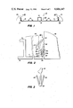
- FIG. 1 is an end elevatonal view of a preferred embodiment of our jamb liner with flange seals
- FIG. 2 is an enlarged end elevational view of the right flange edge of the jamb liner of FIG. 1;
- FIG. 3 is an enlarged and elevational view of the proximal end of the right flange element before insertion into a mechanical interlock with the right flange edge of the jamb liner of FIG. 2;
- FIGS. 4 and 5 are end elevational views of alternative configurations of sealing flange elements usable in our invention.
- Jamb liner 10 includes a pair of sash runs 11 and 12 separated by a parting bead 13.
- a pair of opposed projections 15 in each of the sash runs are L-shaped in cross section and disposed to confront each other.
- Spring covers can be mounted in the interlock formed by projections 15, and a friction shoe traveling with each sash can run in the track between projections 15.
- a resin web 16 preferably extends between sash runs 11 and 12 in the region of parting bead 13 to interconnect the planes of the sash runs and brace their outer edges 21 and 22.
- Web 16 helps resist any squeezing force from trim stops 30 installed so tightly that they urge sash runs 11 and 12 together under parting bead 13.
- Web 16 also strengthens jamb liner 10 against twisting, making it easier to install.
- jamb liner 10 is formed as a generally known base extrusion 24 of substantially rigid resin material, preferably polyvinyl chloride.
- Resilient flange seals 25 arranged at outer sash run edges 21 and 22 are formed differently, however, as explained below.
- Flange seals 25, also extruded of resin material, are formed of a substantially resilient resin, such as polypropylene, having a substantially lower spring rate than the rigid resin of base extrusion 24. This allows flange elements 25 to be flexed or sprung from their home positions in response to light force and to resiliently spring back to their home positions after a flexing force is removed.
- a substantially resilient resin such as polypropylene
- Each flange elements 25 includes a support limb 26 and a sealing fin 27, both of which are thinner in cross section than the rigid resin extrusion 24.
- support limb 26 and sealing fin 27 are preferably less than 0.5 mm thick, compared with the more than 1.0 mm thickness that is preferred for the base extrusion 24.
- sealing fins can be arranged relative to support limbs to form flange elements 25, but we prefer the configuration shown in FIGS. 1-3.
- Sealing fin 27 angles obliquely inward from a distal end 36 of support limb 26 toward the adjacent sash run 11 where it is disposed for resiliently engaging a sash 40.
- flange element 25 preferably leans toward the adjacent trim stop 30 as shown at the left edge of FIG. 1. Then when trim stop 30 is installed against the outer sash run edge 21 of jamb liner 10, it flexes flange element 25 inward; and flange element 25, in resistance to this, engages and seals against trim stop 30. This helps prevent air from leaking between the trim stops and the jamb liner and passing behind the sash runs.
- the oblique span of sealing fin 27 is wider than the space between trim stop 30 and sash 40 so that fin 27 is flexibly compressed between trim stop 30 and sash 40 as best shown in FIG. 2.
- This not only creates a seal between fin 27 engaging and pressing against the surface of sash 40, but it also presses the sash against parting bead 13. This tends to seal each sash both on the side engaged by fin 27 and on the opposite side where the sash engages parting bead 13.
- the scope of the biased resilient spring range of sealing fin 27 is suggested by the distance between the solid and broken line positions of sealing flange 25 in FIG. 2. This is adequate to accommodate manufacturing tolerances in the thickness of a sash and to allow fin 27 to conform to slight irregularities in a sash.
- sealing fin 27 It is also possible to reverse the orientation of sealing fin 27 to engage trim stop 30, rather than sash 40, as shown in FIG. 4.
- a flange element 25 oriented this way engages a surface of sash 40 in the region 36 where the distal end of support limb 26 joins the proximal end of fin 27.
- a disadvantage with this arrangement is that the distal end of fin 27 extends outward from sash run edge 22 of base extrusion 24 where it may be damaged in shipment.
- FIG. 5 Another possibility, illustrated in FIG. 5, is an opposed pair of fins 27a and b each extending obliquely outward from the distal end 36 of support limb 26. Then one fin 27b can engage and seal against trim stop 30, leaving the opposite fin 27a disposed to engage and seal against a surface of sash 40.
- Such a double-finned configuration uses slightly more resilient material and leaves fin 27b extending beyond sash run edge 22 where it is exposed to shipment and installation damage.
- Sealing flanges 25 can be interconnected with base extrusion 24 in several ways. The differences in resin materials may inhibit a direct fusion bond, so we prefer a mechanical interlock such as shown in FIGS. 2 and 3. Other mechanical interlocks are also possible and can be combined with thermal forming accomplished as flange elements 25 are automatically joined to base extrusion 24.
- Our preferred mechanical interlock formed at the outer sash run edges 21 and 22, uses a groove between a pair of spaced-apart legs 23a and 23b having opposed projections 23c constricting the open end of the groove.
- Limbs 29, which tend to spring apart, are then trapped behind confronting lips 23c as shown in FIG. 2 to resist withdrawal of element 25 from base 24. Many variations on such an arrangement are possible.
- Base 24 and a pair of flange elements 25 can all be extruded simultaneously and united downstream of the extruders for forming jamb liner 10 continuously.
- Flange elements 25 can also be preextruded and fed from a supply to join extrusion 24 shortly after it is formed. It may even be possible to feed preextruded flange elements 25 through the extrusion head that forms extrusion 24, directly united with flange elements 25. Automatically joining flange elements 25 and extrusion 24 at extrusion speed eliminates post-assembly of separate components and forms jamb liner 10 as a single end product that can serve on both sides of double-hung window sash.
Landscapes
- Engineering & Computer Science (AREA)
- Civil Engineering (AREA)
- Structural Engineering (AREA)
- Specific Sealing Or Ventilating Devices For Doors And Windows (AREA)
- Support Devices For Sliding Doors (AREA)
Abstract
A sealing jamb liner 10 for double-hung window sash includes a thick and rigid resin extrusion 24 having a pair of sash runs 11 and 12 separated by a parting bead 13. A pair of extruded flange elements 25 formed of a thin, resilient, and low spring rate resin material are mounted along respective outer sash run edges 21 and 22 opposite parting bead 13. Each flange element 25 has a sealing 27 angled obliquely of the adjacent sash run and disposed for resiliently engaging and sealing between a sash and an adjacent trim stop.
Description
Weatherproof seals for jamb liners for double-hung window sash remain unsatisfactory in spite of the many variations that have been tried. A suitable seal must fit well against the sash, seal against the trim stop, accommodate manufacturing tolerances in both the seal and the sash, and yet not unduly increase the effort necessary to raise and lower the sash. The seal must also be wind resistant and tolerant of temperature extremes. Finally, cost is very important in the highly competitive window business, and a suitable seal must do its job without hardly adding to the expense.
We have devised a solution that meets all these requirements. Our extruded resin jamb liner not only has suitable flexible flange seals, but also can be formed at nearly the same price as conventional jamb liners with ineffective seals. Our invention thus offers added sealing advantages at a competitive price.
After many failures at devising flexible flange seals for extruded resin jamb liners, we discovered that separate flange elements with sealing fins can be extruded of resilient and low spring rate resin material that is then interconnected with the outer sash run edges of a substantially rigid resin extrusion having the conventional pair of sash runs separated by a parting bead. The sealing flange elements and the sash run extrusion can be united automatically at full extrusion speed. Sealing fins on the flange elements are disposed obliquely between a sash run and the adjacent trim stop, which they engage and seal against. They span a wide enough space so as to be resiliently compressed between the trim stop and a sash to seal against and bias the sash against the parting bead. Even though the flexible resin material costs more, very little of it is used, and no after-assembly is necessary. Limiting the resilient resin to the sealing flanges also preserves the desirable characteristics and economies of the rigid resin extrusion forming the sash runs and the parting bead.
FIG. 1 is an end elevatonal view of a preferred embodiment of our jamb liner with flange seals;
FIG. 2 is an enlarged end elevational view of the right flange edge of the jamb liner of FIG. 1; and
FIG. 3 is an enlarged and elevational view of the proximal end of the right flange element before insertion into a mechanical interlock with the right flange edge of the jamb liner of FIG. 2; and
FIGS. 4 and 5 are end elevational views of alternative configurations of sealing flange elements usable in our invention.
A resin web 16 preferably extends between sash runs 11 and 12 in the region of parting bead 13 to interconnect the planes of the sash runs and brace their outer edges 21 and 22. Web 16 helps resist any squeezing force from trim stops 30 installed so tightly that they urge sash runs 11 and 12 together under parting bead 13. Web 16 also strengthens jamb liner 10 against twisting, making it easier to install.
Except for the configuration of outer sash run edges 21 and 22 and web 16 interconnecting sash runs 11 and 12, jamb liner 10 is formed as a generally known base extrusion 24 of substantially rigid resin material, preferably polyvinyl chloride. Resilient flange seals 25 arranged at outer sash run edges 21 and 22 are formed differently, however, as explained below.
Each flange elements 25 includes a support limb 26 and a sealing fin 27, both of which are thinner in cross section than the rigid resin extrusion 24. For example, support limb 26 and sealing fin 27 are preferably less than 0.5 mm thick, compared with the more than 1.0 mm thickness that is preferred for the base extrusion 24. There are several ways that sealing fins can be arranged relative to support limbs to form flange elements 25, but we prefer the configuration shown in FIGS. 1-3.
Sealing fin 27 angles obliquely inward from a distal end 36 of support limb 26 toward the adjacent sash run 11 where it is disposed for resiliently engaging a sash 40. In an unflexed state, flange element 25 preferably leans toward the adjacent trim stop 30 as shown at the left edge of FIG. 1. Then when trim stop 30 is installed against the outer sash run edge 21 of jamb liner 10, it flexes flange element 25 inward; and flange element 25, in resistance to this, engages and seals against trim stop 30. This helps prevent air from leaking between the trim stops and the jamb liner and passing behind the sash runs.
Otherwise, the oblique span of sealing fin 27 is wider than the space between trim stop 30 and sash 40 so that fin 27 is flexibly compressed between trim stop 30 and sash 40 as best shown in FIG. 2. This not only creates a seal between fin 27 engaging and pressing against the surface of sash 40, but it also presses the sash against parting bead 13. This tends to seal each sash both on the side engaged by fin 27 and on the opposite side where the sash engages parting bead 13. The scope of the biased resilient spring range of sealing fin 27 is suggested by the distance between the solid and broken line positions of sealing flange 25 in FIG. 2. This is adequate to accommodate manufacturing tolerances in the thickness of a sash and to allow fin 27 to conform to slight irregularities in a sash.
It is also possible to reverse the orientation of sealing fin 27 to engage trim stop 30, rather than sash 40, as shown in FIG. 4. A flange element 25 oriented this way engages a surface of sash 40 in the region 36 where the distal end of support limb 26 joins the proximal end of fin 27. A disadvantage with this arrangement is that the distal end of fin 27 extends outward from sash run edge 22 of base extrusion 24 where it may be damaged in shipment.
Another possibility, illustrated in FIG. 5, is an opposed pair of fins 27a and b each extending obliquely outward from the distal end 36 of support limb 26. Then one fin 27b can engage and seal against trim stop 30, leaving the opposite fin 27a disposed to engage and seal against a surface of sash 40. Such a double-finned configuration uses slightly more resilient material and leaves fin 27b extending beyond sash run edge 22 where it is exposed to shipment and installation damage.
Our preferred mechanical interlock, formed at the outer sash run edges 21 and 22, uses a groove between a pair of spaced- apart legs 23a and 23b having opposed projections 23c constricting the open end of the groove. We also form the proximal end 28 of support limb 26 with a flared pair of limbs 29 that squeeze together when proximal end 28 presses into the groove between legs 23a and b. Limbs 29, which tend to spring apart, are then trapped behind confronting lips 23c as shown in FIG. 2 to resist withdrawal of element 25 from base 24. Many variations on such an arrangement are possible.
Claims (18)
1. In a double-hung window sash jamb liner formed of a substantially rigid resin jamb liner extrusion having a pair of sash runs separated by a parting bead and extending to outer sash run edges respectively adjacent a pair of trim stops, the improvement comprising:
a. flange elements interconnected with said outer sash run edges of said jamb liner extrusion, said flange elements being formed of a resin material that is substantially more resilient and has a substantially lower spring rate than said jamb liner extrusion; and
b. said flange elements each having a sealing fin disposed for resiliently engaging and sealing against said adjacent trim stop and for extending obliquely across a space wider than the distance between said adjacent trim stop and a sash in said sash run so that a sash engaging portion of said sealing fin is resiliently compressed for sealing between said adjacent trim stop and said sash and for biasing said sash against said parting bead.
2. The improvement of claim 1 wherein the thickness of said rigid resin extrusion is more than 1.0 mm, and the thickness of said sealing fin is less than 0.5 mm.
3. The improvement of claim 1 wherein said jamb liner extrusion has a groove in each of said outer sash run edges, and said flange elements are mechanically interlocked with said grooves.
4. The improvement of claim 1 wherein said jamb liner extrusion includes a bracing wall extending between said sash runs in the plane of said sash runs in the region of said parting bead.
5. The improvement of claim 4 wherein said jamb liner extrusion has a groove in each of said outer sash run edges, and said flange elements are mechanically interlocked with said grooves.
6. The improvement of claim 5 wherein the thickness of said rigid resin extrusion is more than 1.0 mm, and the thickness of said sealing fins is less than 0.5 mm.
7. A sealing system for an extruded resin jamb liner having a pair of sash runs separated by a parting bead and located between a pair of trim stops for receiving double-hung window sash, said sealing system comprising:
a. a pair of sealing flange elements formed of a resin material that is substantially more resilient and has a substantially lower spring rate than said jamb liner extrusion, said flange elements being interconnected with outer sash run edges of said jamb liner adjacent said trim stops; and
b. said sealing flange elements having sealing fins disposed for resiliently engaging and sealing against said adjacent trim stops and for extending obliquely across a space wider than the distance between said adjacent trim stops and sash in said sash runs so that sash engaging portions of said sealing fins are resiliently compressed for sealing between said adjacent trim stops and said sash and for biasing said sash against said parting bead.
8. The sealing system of claim 7 wherein said sealing fins are less than 0.5 mm thick.
9. The sealing system of claim 7 wherein said flange elements each have a mechanical interlock for mounting in a groove in an outer sash run edge of said jamb liner.
10. The sealing system of claim 7 wherein said jamb liner has a bracing wall extending between said sash runs in the plane of said sash runs in the region of said parting bead.
11. The sealing system of claim 10 wherein each of said outer sash run edges of said jamb liner has a groove receiving one of said flange elements in a mechanical interlock.
12. The sealing system of claim 11 wherein said sealing fins are less than 0.5 mm thick.
13. A sealing flange mountable on an outer sash run edge of an extruded resin jamb liner for double-hung window sash, said sealing flange comprising:
a. a connector shaped for interconnecting said sealing flange with a slot in said outer sash run edge of said jamb liner;
b. a sealing fin extending resiliently away from said connector, said sealing fin being formed of a resin material that is substantially more resilient and has a substantially lower spring rate than said jamb liner; and
c. said sealing fin being disposed for resiliently engaging a trim stop adjacent said outer sash run edge and for extending obliquely across a space wider than the distance between said trim stop and a sash so that a portion of said seaing fin is resiliently compressed between said trim stop and said sash.
14. The sealing flange of claim 13 wherein said sealing fin is less than 0.5 mm thick.
15. A method of sealing against air flow on either side of an extruded resin jamb liner for double-hung window sash, said jamb liner having outer sash run edges adjacent trim stops and having sash running in said sash runs of said jamb liner, said method comprising:
a. forming sealing flanges of a resin material that is substantially more resilient and has a substantially lower spring rate than said jamb liner;
b. connecting said sealing flanges with slots in said outer sash run edges of said jamb liner; and
c. disposing said sealing flanges for resiliently engaging and sealing against said trim stops adjacent said outer sash run edges and for extending obliquely across a space between said trim stops and sash adjacent said trim stops so as to resiliently engage and seal against said adjacent sash.
16. The method of claim 15 including forming said sealing flange with a thickness of less than 0.5 mm.
17. The method of claim 15 including forming said jamb liner with a bracing wall extending between sash runs of said jamb liner in the plane of said sash runs in the region of a parting bead between said sash runs.
18. The method of claim 15 including using said resilient sealing flanges for biasing said sash against a parting bead between said sash runs.
Priority Applications (3)
| Application Number | Priority Date | Filing Date | Title |
|---|---|---|---|
| US06/622,103 US4606147A (en) | 1984-06-19 | 1984-06-19 | Sealing jamb liner for double-hung window sash |
| EP85107555A EP0165597A3 (en) | 1984-06-19 | 1985-06-19 | Sealing jamb liner for double-hung window sash |
| JP60259640A JPS61117378A (en) | 1984-06-19 | 1985-11-19 | Liner for window sash and seal method |
Applications Claiming Priority (1)
| Application Number | Priority Date | Filing Date | Title |
|---|---|---|---|
| US06/622,103 US4606147A (en) | 1984-06-19 | 1984-06-19 | Sealing jamb liner for double-hung window sash |
Publications (1)
| Publication Number | Publication Date |
|---|---|
| US4606147A true US4606147A (en) | 1986-08-19 |
Family
ID=24492952
Family Applications (1)
| Application Number | Title | Priority Date | Filing Date |
|---|---|---|---|
| US06/622,103 Expired - Fee Related US4606147A (en) | 1984-06-19 | 1984-06-19 | Sealing jamb liner for double-hung window sash |
Country Status (3)
| Country | Link |
|---|---|
| US (1) | US4606147A (en) |
| EP (1) | EP0165597A3 (en) |
| JP (1) | JPS61117378A (en) |
Cited By (16)
| Publication number | Priority date | Publication date | Assignee | Title |
|---|---|---|---|---|
| USD300464S (en) | 1987-02-24 | 1989-03-28 | Davidson Jack E | Weatherstripping for doors and the like |
| US4916863A (en) * | 1989-06-02 | 1990-04-17 | Schlegel Corporation | Jamb liner weatherseal |
| US5375376A (en) * | 1993-01-21 | 1994-12-27 | Crane Plastics Company Limited Partnership | Polymeric sealing/spring strip and extrusion method of producing same |
| USD368534S (en) | 1994-11-17 | 1996-04-02 | Delaware Capital Formation Inc. | Interlocking thermal breaker extrusion |
| US20040011476A1 (en) * | 2002-07-22 | 2004-01-22 | Schroder Paul D. | One-way drive for window coverings |
| US20050284584A1 (en) * | 2002-07-22 | 2005-12-29 | Pella Corporation | One-way drive for window coverings |
| US20060130980A1 (en) * | 2002-07-22 | 2006-06-22 | Pella Corporation | Window covering leveling mechanism |
| US20060169418A1 (en) * | 2002-07-22 | 2006-08-03 | Pella Corporation | Window covering leveling method |
| US20060254151A1 (en) * | 2005-05-12 | 2006-11-16 | Marvin Lumber And Cedar Company, D/B/A Marvin Windows And Doors | Structural filler system for a window or door |
| US7631465B2 (en) | 2005-05-12 | 2009-12-15 | Marvin Lumber And Cedar Company | Jamb adjustment and securement assembly and methods therefor |
| US20110296776A1 (en) * | 2010-06-04 | 2011-12-08 | Milgard Manufacturing Incorporated | Sash binder |
| US20140260012A1 (en) * | 2004-10-15 | 2014-09-18 | Thomas Bren | Water intrusion prevention method and apparatus |
| USD920087S1 (en) | 2018-09-12 | 2021-05-25 | Megawall Pty Ltd | Connector for a building panel |
| USD942786S1 (en) * | 2018-10-18 | 2022-02-08 | SieMatic Möbelwerke GmbH & Co. KG | Furniture section |
| USD942787S1 (en) * | 2018-03-29 | 2022-02-08 | Nashville Wire Products Manufacturing Company, Llc | Shelf stop wall |
| USD946950S1 (en) * | 2018-04-10 | 2022-03-29 | SieMatic Möbelwerke GmbH & Co. KG | Section for furniture |
Citations (8)
| Publication number | Priority date | Publication date | Assignee | Title |
|---|---|---|---|---|
| US2122366A (en) * | 1938-01-31 | 1938-06-28 | W J Dennis & Company | Weather strip construction |
| US2273279A (en) * | 1938-03-28 | 1942-02-17 | Louis A Macklanburg | Window sash assembly and weather strip therefor |
| US2744297A (en) * | 1953-07-13 | 1956-05-08 | Chamberlin Company Of America | Combination guide and weatherstrip for sliding window constructions |
| US2917788A (en) * | 1956-09-06 | 1959-12-22 | Abert A Kunkel | Liner for frame members |
| US3269074A (en) * | 1963-07-22 | 1966-08-30 | Armstadt Mfg Ltd | Sash and frame for windows and doors |
| US3499248A (en) * | 1968-02-26 | 1970-03-10 | Hans Baer | Prefabricated window and frame structure having removable sash-balanced window panels |
| US3633317A (en) * | 1970-07-01 | 1972-01-11 | Zegers Inc | Clip for combination weatherstrip and sash balance units |
| US4373295A (en) * | 1980-11-12 | 1983-02-15 | A.M.S. Corporation | Resilient friction sash balance |
Family Cites Families (3)
| Publication number | Priority date | Publication date | Assignee | Title |
|---|---|---|---|---|
| JPS4824360U (en) * | 1971-07-26 | 1973-03-22 | ||
| US4096665A (en) * | 1977-03-10 | 1978-06-27 | Ellingson Jr Chester W | Window sealing structure |
| JPS5613312Y2 (en) * | 1977-08-23 | 1981-03-27 |
-
1984
- 1984-06-19 US US06/622,103 patent/US4606147A/en not_active Expired - Fee Related
-
1985
- 1985-06-19 EP EP85107555A patent/EP0165597A3/en not_active Withdrawn
- 1985-11-19 JP JP60259640A patent/JPS61117378A/en active Pending
Patent Citations (8)
| Publication number | Priority date | Publication date | Assignee | Title |
|---|---|---|---|---|
| US2122366A (en) * | 1938-01-31 | 1938-06-28 | W J Dennis & Company | Weather strip construction |
| US2273279A (en) * | 1938-03-28 | 1942-02-17 | Louis A Macklanburg | Window sash assembly and weather strip therefor |
| US2744297A (en) * | 1953-07-13 | 1956-05-08 | Chamberlin Company Of America | Combination guide and weatherstrip for sliding window constructions |
| US2917788A (en) * | 1956-09-06 | 1959-12-22 | Abert A Kunkel | Liner for frame members |
| US3269074A (en) * | 1963-07-22 | 1966-08-30 | Armstadt Mfg Ltd | Sash and frame for windows and doors |
| US3499248A (en) * | 1968-02-26 | 1970-03-10 | Hans Baer | Prefabricated window and frame structure having removable sash-balanced window panels |
| US3633317A (en) * | 1970-07-01 | 1972-01-11 | Zegers Inc | Clip for combination weatherstrip and sash balance units |
| US4373295A (en) * | 1980-11-12 | 1983-02-15 | A.M.S. Corporation | Resilient friction sash balance |
Cited By (26)
| Publication number | Priority date | Publication date | Assignee | Title |
|---|---|---|---|---|
| USD300464S (en) | 1987-02-24 | 1989-03-28 | Davidson Jack E | Weatherstripping for doors and the like |
| US4916863A (en) * | 1989-06-02 | 1990-04-17 | Schlegel Corporation | Jamb liner weatherseal |
| US5375376A (en) * | 1993-01-21 | 1994-12-27 | Crane Plastics Company Limited Partnership | Polymeric sealing/spring strip and extrusion method of producing same |
| USD368534S (en) | 1994-11-17 | 1996-04-02 | Delaware Capital Formation Inc. | Interlocking thermal breaker extrusion |
| US7174941B2 (en) | 2002-07-22 | 2007-02-13 | Pella Corporation | One-way drive for window coverings |
| US20040011476A1 (en) * | 2002-07-22 | 2004-01-22 | Schroder Paul D. | One-way drive for window coverings |
| US20050284584A1 (en) * | 2002-07-22 | 2005-12-29 | Pella Corporation | One-way drive for window coverings |
| US7021360B2 (en) | 2002-07-22 | 2006-04-04 | Pella Corporation | One-way drive for window coverings |
| US20060130980A1 (en) * | 2002-07-22 | 2006-06-22 | Pella Corporation | Window covering leveling mechanism |
| US20060169418A1 (en) * | 2002-07-22 | 2006-08-03 | Pella Corporation | Window covering leveling method |
| US9945172B2 (en) | 2004-10-15 | 2018-04-17 | T-Stop Products, Llc | Water intrusion prevention method and apparatus |
| US9422762B2 (en) * | 2004-10-15 | 2016-08-23 | Thomas Bren | Water intrusion prevention method and apparatus |
| US20140260012A1 (en) * | 2004-10-15 | 2014-09-18 | Thomas Bren | Water intrusion prevention method and apparatus |
| US9038334B2 (en) * | 2004-10-15 | 2015-05-26 | Thomas Bren | Water intrusion prevention method and apparatus |
| US7631465B2 (en) | 2005-05-12 | 2009-12-15 | Marvin Lumber And Cedar Company | Jamb adjustment and securement assembly and methods therefor |
| US20060254151A1 (en) * | 2005-05-12 | 2006-11-16 | Marvin Lumber And Cedar Company, D/B/A Marvin Windows And Doors | Structural filler system for a window or door |
| US7552562B2 (en) | 2005-05-12 | 2009-06-30 | Marvin Lumber And Cedar Company | Structural filler system for a window or door |
| US8584426B2 (en) * | 2010-06-04 | 2013-11-19 | Milgard Manufacturing Incorporated | Sash binder |
| US20110296776A1 (en) * | 2010-06-04 | 2011-12-08 | Milgard Manufacturing Incorporated | Sash binder |
| USD942787S1 (en) * | 2018-03-29 | 2022-02-08 | Nashville Wire Products Manufacturing Company, Llc | Shelf stop wall |
| USD946950S1 (en) * | 2018-04-10 | 2022-03-29 | SieMatic Möbelwerke GmbH & Co. KG | Section for furniture |
| USD966764S1 (en) * | 2018-04-10 | 2022-10-18 | SieMatic Möbelwerke GmbH & Co. KG | Section for furniture |
| USD920087S1 (en) | 2018-09-12 | 2021-05-25 | Megawall Pty Ltd | Connector for a building panel |
| USD920086S1 (en) * | 2018-09-12 | 2021-05-25 | Megawall Pty Ltd | Connector for a building panel |
| USD923822S1 (en) | 2018-09-12 | 2021-06-29 | Megawall Pty Ltd | Connector for a building panel |
| USD942786S1 (en) * | 2018-10-18 | 2022-02-08 | SieMatic Möbelwerke GmbH & Co. KG | Furniture section |
Also Published As
| Publication number | Publication date |
|---|---|
| EP0165597A3 (en) | 1986-12-30 |
| JPS61117378A (en) | 1986-06-04 |
| EP0165597A2 (en) | 1985-12-27 |
Similar Documents
| Publication | Publication Date | Title |
|---|---|---|
| US4606147A (en) | Sealing jamb liner for double-hung window sash | |
| CA1167703A (en) | Window frame assembly with frame shaped locking member | |
| US4781003A (en) | Expansion joint seal, frame and assembly | |
| US4555885A (en) | Filler strip with locking clip | |
| US3331171A (en) | Joint covers | |
| US6182405B1 (en) | Window frame structure | |
| US5155958A (en) | Fastening and support system for architectural panels | |
| JP3678753B2 (en) | Frame molding material for switch cabinet frame structure | |
| CA1166815A (en) | Framing system for demountable walls or the like | |
| US3212225A (en) | Glass setting assembly | |
| CA2172118C (en) | Runner-trim connector | |
| US5950377A (en) | Deck structure | |
| US3340663A (en) | Interlocking window framing system | |
| US5601050A (en) | Sectional windshield system for boats | |
| KR20030001395A (en) | A flooring material comprising sheet-shaped floor elements which are joined by means of joining members | |
| CA1164620A (en) | Structural members modules | |
| US4793114A (en) | Window sill construction | |
| BG61623B1 (en) | Set of composite steel-and-wooden sections for door andwindow frames | |
| IE47934B1 (en) | A device for joining panels | |
| US4395080A (en) | Construction set for the manufacture of frames for furniture | |
| GB2065744A (en) | Building panels | |
| GB2078837A (en) | Glazing bars | |
| US3758997A (en) | Building wall assembly | |
| EP0650546B1 (en) | Lead-through structure for a wall | |
| GB2125844A (en) | Connecting building panels |
Legal Events
| Date | Code | Title | Description |
|---|---|---|---|
| AS | Assignment |
Owner name: CALDWELL MANUFACTURING COMPANY, 64 COMMERCIAL STRE Free format text: ASSIGNMENT OF ASSIGNORS INTEREST.;ASSIGNORS:DEWITT, VERN T.;HALTOF, GARRY P.;REEL/FRAME:004480/0655 Effective date: 19840618 |
|
| FEPP | Fee payment procedure |
Free format text: PAYOR NUMBER ASSIGNED (ORIGINAL EVENT CODE: ASPN); ENTITY STATUS OF PATENT OWNER: SMALL ENTITY |
|
| FPAY | Fee payment |
Year of fee payment: 4 |
|
| REMI | Maintenance fee reminder mailed | ||
| LAPS | Lapse for failure to pay maintenance fees | ||
| FP | Lapsed due to failure to pay maintenance fee |
Effective date: 19940824 |
|
| STCH | Information on status: patent discontinuation |
Free format text: PATENT EXPIRED DUE TO NONPAYMENT OF MAINTENANCE FEES UNDER 37 CFR 1.362 |