US4603585A - Method for representing elastic parameters of object surfaces - Google Patents
Method for representing elastic parameters of object surfaces Download PDFInfo
- Publication number
- US4603585A US4603585A US06/712,110 US71211085A US4603585A US 4603585 A US4603585 A US 4603585A US 71211085 A US71211085 A US 71211085A US 4603585 A US4603585 A US 4603585A
- Authority
- US
- United States
- Prior art keywords
- point
- frequency
- difference signal
- steps
- signal
- Prior art date
- Legal status (The legal status is an assumption and is not a legal conclusion. Google has not performed a legal analysis and makes no representation as to the accuracy of the status listed.)
- Expired - Fee Related
Links
Images

Classifications
-
- G—PHYSICS
- G01—MEASURING; TESTING
- G01N—INVESTIGATING OR ANALYSING MATERIALS BY DETERMINING THEIR CHEMICAL OR PHYSICAL PROPERTIES
- G01N29/00—Investigating or analysing materials by the use of ultrasonic, sonic or infrasonic waves; Visualisation of the interior of objects by transmitting ultrasonic or sonic waves through the object
- G01N29/34—Generating the ultrasonic, sonic or infrasonic waves, e.g. electronic circuits specially adapted therefor
- G01N29/348—Generating the ultrasonic, sonic or infrasonic waves, e.g. electronic circuits specially adapted therefor with frequency characteristics, e.g. single frequency signals, chirp signals
-
- G—PHYSICS
- G01—MEASURING; TESTING
- G01N—INVESTIGATING OR ANALYSING MATERIALS BY DETERMINING THEIR CHEMICAL OR PHYSICAL PROPERTIES
- G01N29/00—Investigating or analysing materials by the use of ultrasonic, sonic or infrasonic waves; Visualisation of the interior of objects by transmitting ultrasonic or sonic waves through the object
- G01N29/04—Analysing solids
- G01N29/041—Analysing solids on the surface of the material, e.g. using Lamb, Rayleigh or shear waves
-
- G—PHYSICS
- G01—MEASURING; TESTING
- G01N—INVESTIGATING OR ANALYSING MATERIALS BY DETERMINING THEIR CHEMICAL OR PHYSICAL PROPERTIES
- G01N29/00—Investigating or analysing materials by the use of ultrasonic, sonic or infrasonic waves; Visualisation of the interior of objects by transmitting ultrasonic or sonic waves through the object
- G01N29/04—Analysing solids
- G01N29/06—Visualisation of the interior, e.g. acoustic microscopy
- G01N29/0654—Imaging
- G01N29/0681—Imaging by acoustic microscopy, e.g. scanning acoustic microscopy
-
- G—PHYSICS
- G01—MEASURING; TESTING
- G01N—INVESTIGATING OR ANALYSING MATERIALS BY DETERMINING THEIR CHEMICAL OR PHYSICAL PROPERTIES
- G01N29/00—Investigating or analysing materials by the use of ultrasonic, sonic or infrasonic waves; Visualisation of the interior of objects by transmitting ultrasonic or sonic waves through the object
- G01N29/22—Details, e.g. general constructional or apparatus details
- G01N29/221—Arrangements for directing or focusing the acoustical waves
-
- G—PHYSICS
- G01—MEASURING; TESTING
- G01N—INVESTIGATING OR ANALYSING MATERIALS BY DETERMINING THEIR CHEMICAL OR PHYSICAL PROPERTIES
- G01N29/00—Investigating or analysing materials by the use of ultrasonic, sonic or infrasonic waves; Visualisation of the interior of objects by transmitting ultrasonic or sonic waves through the object
- G01N29/22—Details, e.g. general constructional or apparatus details
- G01N29/24—Probes
- G01N29/2456—Focusing probes
-
- G—PHYSICS
- G01—MEASURING; TESTING
- G01N—INVESTIGATING OR ANALYSING MATERIALS BY DETERMINING THEIR CHEMICAL OR PHYSICAL PROPERTIES
- G01N29/00—Investigating or analysing materials by the use of ultrasonic, sonic or infrasonic waves; Visualisation of the interior of objects by transmitting ultrasonic or sonic waves through the object
- G01N29/22—Details, e.g. general constructional or apparatus details
- G01N29/26—Arrangements for orientation or scanning by relative movement of the head and the sensor
-
- G—PHYSICS
- G01—MEASURING; TESTING
- G01N—INVESTIGATING OR ANALYSING MATERIALS BY DETERMINING THEIR CHEMICAL OR PHYSICAL PROPERTIES
- G01N2291/00—Indexing codes associated with group G01N29/00
- G01N2291/01—Indexing codes associated with the measuring variable
- G01N2291/015—Attenuation, scattering
-
- G—PHYSICS
- G01—MEASURING; TESTING
- G01N—INVESTIGATING OR ANALYSING MATERIALS BY DETERMINING THEIR CHEMICAL OR PHYSICAL PROPERTIES
- G01N2291/00—Indexing codes associated with group G01N29/00
- G01N2291/04—Wave modes and trajectories
- G01N2291/042—Wave modes
- G01N2291/0423—Surface waves, e.g. Rayleigh waves, Love waves
-
- G—PHYSICS
- G01—MEASURING; TESTING
- G01N—INVESTIGATING OR ANALYSING MATERIALS BY DETERMINING THEIR CHEMICAL OR PHYSICAL PROPERTIES
- G01N2291/00—Indexing codes associated with group G01N29/00
- G01N2291/04—Wave modes and trajectories
- G01N2291/042—Wave modes
- G01N2291/0426—Bulk waves, e.g. quartz crystal microbalance, torsional waves
-
- G—PHYSICS
- G01—MEASURING; TESTING
- G01N—INVESTIGATING OR ANALYSING MATERIALS BY DETERMINING THEIR CHEMICAL OR PHYSICAL PROPERTIES
- G01N2291/00—Indexing codes associated with group G01N29/00
- G01N2291/04—Wave modes and trajectories
- G01N2291/044—Internal reflections (echoes), e.g. on walls or defects
-
- G—PHYSICS
- G01—MEASURING; TESTING
- G01N—INVESTIGATING OR ANALYSING MATERIALS BY DETERMINING THEIR CHEMICAL OR PHYSICAL PROPERTIES
- G01N2291/00—Indexing codes associated with group G01N29/00
- G01N2291/10—Number of transducers
- G01N2291/101—Number of transducers one transducer
-
- G—PHYSICS
- G01—MEASURING; TESTING
- G01N—INVESTIGATING OR ANALYSING MATERIALS BY DETERMINING THEIR CHEMICAL OR PHYSICAL PROPERTIES
- G01N2291/00—Indexing codes associated with group G01N29/00
- G01N2291/26—Scanned objects
- G01N2291/263—Surfaces
- G01N2291/2632—Surfaces flat
Definitions
- the invention relates to a method for representing elastic parameters of object surfaces by scanning the object surface with a focused acoustic beam and detecting the interference between the ultrasonic rays specularly reflected at the object surface and the ultrasonic rays emitted from the object surface after excitation of surface waves.
- Scanning of an object surface by means of a focused acoustic beam can be carried out by means of an acoustic microscope operating in a reflection mode.
- an acoustic lens arrangement is focused onto a certain object plane which is then scanned in a raster-patterned movement perpendicularly to the direction of propagation of the acoustic beam (x/y scanning).
- the signal reflected by the object is isolated from the emitted signal and used for image representation.
- V(z) curves obtained by this means are produced by interference of a specularly reflected ultrasonic beam with an ultrasonic beam which is returning to the acoustic lens arrangement, after being laterally offset, as a result of the excitation of surface waves.
- the respective output voltage at the acoustic transducer is a reflection signal which corresponds to the integration of the acoustic interference field over the area of the transducer.
- the present invention is directed toward providing a method by means of which the information contained in the image contrast on the distribution of elastic parameters existing in the object surface scanned can be made visible.
- the method according to the invention utilizes the finding that the curve shapes obtained with the known V(z) measurements essentially depend on the type of the surface wave excited in each case.
- the amplitude and wavelength of this surface wave is influenced by the elastic characteristics of the material at the object point irradiated.
- the possible extent of the surface wave is affected by the magnitude of z.
- different amplitudes and phase relationships are obtained for the ultrasonic beams which are generated by the surface waves, received by the acoustic lens arrangement, and which interfere with the rays specularly reflected at the object surface.
- the V(z) curves show typical interference maxima and minima.
- the z-independent image signals are suppressed by taking an image from two object planes and determining the difference between them.
- the acoustic image then shows the change in contrast between the two images originally taken.
- the change in contrast thus made visible is a direct image of the distribution of the elastic parameters in the object surface.
- Both the method involving position change and the method involving frequency change can be carried out in such a manner that initially in each case the object is completely scanned and the images obtained are stored.
- this requires a relatively large expenditure for providing the necessary memory capacity.
- very high demands are made on the quality of the image taking since the parameters, which are constant during the image taking, must not change during the scanning which varies with time. For this reason, it is of advantage to carry out the switching-over operations at each scanning point before going to the next scanning point.
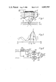
- FIG. 1 shows an acousto-microscopic reflection arrangement and the diagrammatic optical path
- FIG. 2 shows V(z) curves diagrammatically for various frequencies
- FIG. 3 shows a circuit arrangement for alternating frequency switching
- FIG. 4 shows another circuit arrangement for alternating frequency switching
- FIG. 5 shows a circuit arrangement for generating the amplitude difference including weighting of the measurement pulses
- FIG. 6 shows another circuit arrangement for forming the difference.
- FIG. 1 shows a greatly simplified representation of an acousto-microscopic reflection arrangement. It consists of an acoustic lens 1 including a piezoelectric transmitter 2. This is used first for generating a planar ultrasonic wave front indicated by the ray 3. The spherical cavity 4 in the acoustic lens focuses the acoustic beam onto the object 5 to be examined. The intermediate space between the acoustic lens 1 and the object 5 is filled with an immersing medium, not shown in this Figure.
- the ray 3 impinging on the object surface is specularly reflected at the surface as ray 3'.
- a part of the ray 3 penetrates into the object and is reflected back out of the focal plane as ray 3" into the acoustic lens.
- Another ray 3"' is generated by the surface wave 6.
- all three rays directed towards the acoustic lens correspond to planar soundwaves reaching the transmitter with a mutual offset in phase and interfering with each other.
- the transmitter integrates the acoustic field and converts it into electric signals.
- the method operating with frequency switching is hardly influenced by the layer structure below the object surface.
- the change in frequency influences the depth of penetration of the ray 3 and the focus position
- the changes in the ray 3" are much smaller than with a change in position.
- the influence of the change in frequency on the depth of penetration and on the wavelength of the surface wave 6 and thus on the ray 3"' is considerable.
- the difference signal after frequency switching, formed in accordance with the invention reacts also to smaller changes in the elastic parameters in the object surface. Therefore, this method is more sensitive.
- FIG. 2 shows the typical variation of a V(z) curve. No interference maxima or minima whatever are observed for positive z values. These appear only for negative z values.
- the continuous curve is for a frequency f 1 and the dashed curve is for a frequency f 2 .
- the diagram depicts the dependence of individual signal values V on a change in position or a change in frequency, respectively.
- the differential image shows only the frequency-dependent parts of the object.
- the frequency-dependent depth of penetration of the surface wave becomes significant.
- the resultant image is therefore very sensitively dependent on a layer thickness structure which is of the order of magnitude of the depth of penetration of the surface wave.
- the f 1 and f 2 pulses are amplified in a power amplifier 15 and are successively conducted via a circulator 16 to the piezoelectric transmitter, not shown, of an acoustic lens 17. After that, the input line is blocked by the circular 16 so that the f 1 and f 2 measurement signals received by the acoustic lens 17 can be fed undisturbed into the receiver section of the circuit arrangement.
- the signal output C of the intermediate-frequency amplifier 23 appear pulses the amplitude of which represents the acousto-microscopic measurement signal for two different frequencies in alternating sequence. Since the repetition frequency of the pulses is relatively high and a relatively slow mechanical scanning method (x/y scan) is used, the successive pulses can be considered to have originated from the same object point.
- two sample-and-hold components 50, 51 are inserted into the line C carrying the measurement signal, in such a manner that one samples only the f 1 measurement pulses and the other one only the f 2 measurement pulses.
- the sample-and-hold components 50, 51 are enabled by two AND gates 52, 53 as a function of the switching signals A and B.
- the signal A can also be delayed in a delay unit 54 by the transit time between the excitation signal at the acoustic lens 17 and reception of the measurement signal.
- the analog difference forming circuits according to FIGS. 5 and 6 can also be used for a measurement signal sequence produced with an alternating z position setting at the signal input C.
- the control signal B defines the respective focus position of the acoustic lens 17 which is suitably generated by appropriate z adjustment of the object stage when the lens is performing the x/y scanning movement.
- a suitable adjustment is, for example, a piezoelectric adjustment of the object stage in the z direction.
- the measurement signals can also be suitably converted in each case into digital values and the forming of the difference and possible weighting of the signals carried out in a computer. This will be advantageous especially if the object scanning from one plane or at one frequency is to be followed also by automatic image analysis.
Landscapes
- Physics & Mathematics (AREA)
- Health & Medical Sciences (AREA)
- Life Sciences & Earth Sciences (AREA)
- Chemical & Material Sciences (AREA)
- Analytical Chemistry (AREA)
- Biochemistry (AREA)
- General Health & Medical Sciences (AREA)
- General Physics & Mathematics (AREA)
- Immunology (AREA)
- Pathology (AREA)
- Acoustics & Sound (AREA)
- Investigating Or Analyzing Materials By The Use Of Ultrasonic Waves (AREA)
Applications Claiming Priority (2)
| Application Number | Priority Date | Filing Date | Title |
|---|---|---|---|
| DE3409929 | 1984-03-17 | ||
| DE19843409929 DE3409929A1 (de) | 1984-03-17 | 1984-03-17 | Verfahren zur darstellung elastischer parameter in objektoberflaechen |
Publications (1)
| Publication Number | Publication Date |
|---|---|
| US4603585A true US4603585A (en) | 1986-08-05 |
Family
ID=6230871
Family Applications (1)
| Application Number | Title | Priority Date | Filing Date |
|---|---|---|---|
| US06/712,110 Expired - Fee Related US4603585A (en) | 1984-03-17 | 1985-03-15 | Method for representing elastic parameters of object surfaces |
Country Status (4)
| Country | Link |
|---|---|
| US (1) | US4603585A (de) |
| EP (1) | EP0155504B1 (de) |
| JP (1) | JPS60218062A (de) |
| DE (2) | DE3409929A1 (de) |
Cited By (5)
| Publication number | Priority date | Publication date | Assignee | Title |
|---|---|---|---|---|
| US4694699A (en) * | 1986-06-30 | 1987-09-22 | Universite De Sherbrooke | Acoustic microscopy |
| US4730494A (en) * | 1985-10-07 | 1988-03-15 | Hitachi, Ltd. | Method for examining a surface of a sample by means of ultrasound |
| US5922961A (en) * | 1996-05-10 | 1999-07-13 | The United States Of America As Represented By The Secretary Of Commerce | Time and polarization resolved acoustic microscope |
| US20030230144A1 (en) * | 2002-06-18 | 2003-12-18 | General Electric Company | Ultrasonic transducer |
| US20070044544A1 (en) * | 2005-08-31 | 2007-03-01 | Dmytro Chumakov | Method and apparatus for determining surface characteristics by using spm techniques with acoustic excitation and real-time digitizing |
Families Citing this family (4)
| Publication number | Priority date | Publication date | Assignee | Title |
|---|---|---|---|---|
| DE3522491A1 (de) * | 1985-06-24 | 1987-01-02 | Leitz Ernst Gmbh | Akustische linsenanordnung |
| US5240370A (en) * | 1990-06-01 | 1993-08-31 | Komori Corporation | Pile board inserting method and a pile board inserting machine for carrying out the same |
| DE4224209C2 (de) * | 1991-07-23 | 1996-05-23 | Olympus Optical Co | Ultraschallmeßvorrichtung |
| GB2363306B (en) * | 2000-05-05 | 2002-11-13 | Acoustical Tech Sg Pte Ltd | Acoustic microscope |
Citations (2)
| Publication number | Priority date | Publication date | Assignee | Title |
|---|---|---|---|---|
| US4459852A (en) * | 1981-07-08 | 1984-07-17 | Noriyoshi Chubachi | Acoustic microscope using line-focus acoustic beam |
| US4503708A (en) * | 1983-02-07 | 1985-03-12 | Board Of Trustees Of The Leland Stanford Junior University | Reflection acoustic microscope for precision differential phase imaging |
Family Cites Families (4)
| Publication number | Priority date | Publication date | Assignee | Title |
|---|---|---|---|---|
| JPS5325485A (en) * | 1976-08-21 | 1978-03-09 | Asahi Chemical Ind | Method of inspecting defects of carbon electrode |
| JPS5788333A (en) * | 1980-11-25 | 1982-06-02 | Hitachi Ltd | Meausring device for stress distribution |
| JPS5822978A (ja) * | 1981-08-04 | 1983-02-10 | Koji Toda | 超音波装置 |
| JPS5883257A (ja) * | 1981-11-13 | 1983-05-19 | Noritoshi Nakabachi | 超音波顕微鏡 |
-
1984
- 1984-03-17 DE DE19843409929 patent/DE3409929A1/de not_active Withdrawn
-
1985
- 1985-02-14 DE DE8585101609T patent/DE3583447D1/de not_active Expired - Fee Related
- 1985-02-14 EP EP85101609A patent/EP0155504B1/de not_active Expired - Lifetime
- 1985-03-13 JP JP60048464A patent/JPS60218062A/ja active Pending
- 1985-03-15 US US06/712,110 patent/US4603585A/en not_active Expired - Fee Related
Patent Citations (2)
| Publication number | Priority date | Publication date | Assignee | Title |
|---|---|---|---|---|
| US4459852A (en) * | 1981-07-08 | 1984-07-17 | Noriyoshi Chubachi | Acoustic microscope using line-focus acoustic beam |
| US4503708A (en) * | 1983-02-07 | 1985-03-12 | Board Of Trustees Of The Leland Stanford Junior University | Reflection acoustic microscope for precision differential phase imaging |
Cited By (8)
| Publication number | Priority date | Publication date | Assignee | Title |
|---|---|---|---|---|
| US4730494A (en) * | 1985-10-07 | 1988-03-15 | Hitachi, Ltd. | Method for examining a surface of a sample by means of ultrasound |
| US4694699A (en) * | 1986-06-30 | 1987-09-22 | Universite De Sherbrooke | Acoustic microscopy |
| US5922961A (en) * | 1996-05-10 | 1999-07-13 | The United States Of America As Represented By The Secretary Of Commerce | Time and polarization resolved acoustic microscope |
| US20030230144A1 (en) * | 2002-06-18 | 2003-12-18 | General Electric Company | Ultrasonic transducer |
| EP1393821A1 (de) * | 2002-06-18 | 2004-03-03 | General Electric Company | Ultraschallwandler |
| US6952967B2 (en) | 2002-06-18 | 2005-10-11 | General Electric Company | Ultrasonic transducer |
| US20070044544A1 (en) * | 2005-08-31 | 2007-03-01 | Dmytro Chumakov | Method and apparatus for determining surface characteristics by using spm techniques with acoustic excitation and real-time digitizing |
| US7441446B2 (en) * | 2005-08-31 | 2008-10-28 | Advanced Micro Devices, Inc. | Method and apparatus for determining surface characteristics by using SPM techniques with acoustic excitation and real-time digitizing |
Also Published As
| Publication number | Publication date |
|---|---|
| DE3583447D1 (de) | 1991-08-22 |
| EP0155504A3 (en) | 1988-10-19 |
| DE3409929A1 (de) | 1985-09-26 |
| EP0155504A2 (de) | 1985-09-25 |
| JPS60218062A (ja) | 1985-10-31 |
| EP0155504B1 (de) | 1991-07-17 |
Similar Documents
| Publication | Publication Date | Title |
|---|---|---|
| US4541281A (en) | Ultrasonic microscope system | |
| CA1129539A (en) | Ultrasonic imaging system utilizing dynamic and pseudo-dynamic focusing | |
| US4518992A (en) | Acoustic imaging system and method | |
| US4378596A (en) | Multi-channel sonic receiver with combined time-gain control and heterodyne inputs | |
| EP0642036B1 (de) | Ultraschall-Diagnosegerät | |
| US4442713A (en) | Frequency varied ultrasonic imaging array | |
| US4603585A (en) | Method for representing elastic parameters of object surfaces | |
| US4503708A (en) | Reflection acoustic microscope for precision differential phase imaging | |
| US7666142B2 (en) | Ultrasound doppler diagnostic apparatus and image data generating method | |
| JPH08317926A (ja) | 超音波断層装置 | |
| US4862892A (en) | Ultrasonic reflex transmission imaging method and apparatus with artifact removal | |
| US5349862A (en) | Apparatus for measuring the velocity of ultrasonic sound in terms of V(Z) characteristics and ultrasonic microscope using that apparatus | |
| US5085081A (en) | Ultrasonic imaging apparatus without phase distortion | |
| US4491020A (en) | Ultrasonic microscope | |
| US4534359A (en) | Method and means for determining frequency selective tissue attenuation in a baseband ultrasonic imaging system | |
| US4938225A (en) | Ultrasonic echograph utilizing at least one piezoelectric transducer with an associated random phase screen, and method of scanning an object by means of such an echograph | |
| EP0502199A1 (de) | Ultraschallmikroskop | |
| US4386530A (en) | Ultrasonic imaging equipment | |
| JPH0464350A (ja) | 超音波イメージング装置 | |
| US3890829A (en) | Method and apparatus for acoustical imaging | |
| US4620443A (en) | Low frequency acoustic microscope | |
| Quate | A scanning acoustic microscope | |
| JPH0545346A (ja) | 超音波探触子 | |
| JPS61247960A (ja) | エコ−超音波像表示方法及び装置 | |
| SU1518784A1 (ru) | Способ формировани акустических изображений |
Legal Events
| Date | Code | Title | Description |
|---|---|---|---|
| AS | Assignment |
Owner name: ERNST LEITZ WETZLAR GMBH, D-6330 WETZLAR 1, GERMAN Free format text: ASSIGNMENT OF ASSIGNORS INTEREST.;ASSIGNOR:ATALAR, ABDULLAH;REEL/FRAME:004384/0492 Effective date: 19850306 |
|
| FEPP | Fee payment procedure |
Free format text: PAYOR NUMBER ASSIGNED (ORIGINAL EVENT CODE: ASPN); ENTITY STATUS OF PATENT OWNER: LARGE ENTITY |
|
| FPAY | Fee payment |
Year of fee payment: 4 |
|
| FPAY | Fee payment |
Year of fee payment: 8 |
|
| REMI | Maintenance fee reminder mailed | ||
| LAPS | Lapse for failure to pay maintenance fees | ||
| FP | Lapsed due to failure to pay maintenance fee |
Effective date: 19980805 |
|
| STCH | Information on status: patent discontinuation |
Free format text: PATENT EXPIRED DUE TO NONPAYMENT OF MAINTENANCE FEES UNDER 37 CFR 1.362 |