US4596286A - Rotary processor - Google Patents
Rotary processor Download PDFInfo
- Publication number
- US4596286A US4596286A US06/658,723 US65872384A US4596286A US 4596286 A US4596286 A US 4596286A US 65872384 A US65872384 A US 65872384A US 4596286 A US4596286 A US 4596286A
- Authority
- US
- United States
- Prior art keywords
- shaft
- subassemblies
- coil
- coils
- segments
- Prior art date
- Legal status (The legal status is an assumption and is not a legal conclusion. Google has not performed a legal analysis and makes no representation as to the accuracy of the status listed.)
- Expired - Fee Related
Links
Images


Classifications
-
- F—MECHANICAL ENGINEERING; LIGHTING; HEATING; WEAPONS; BLASTING
- F28—HEAT EXCHANGE IN GENERAL
- F28D—HEAT-EXCHANGE APPARATUS, NOT PROVIDED FOR IN ANOTHER SUBCLASS, IN WHICH THE HEAT-EXCHANGE MEDIA DO NOT COME INTO DIRECT CONTACT
- F28D11/00—Heat-exchange apparatus employing moving conduits
- F28D11/02—Heat-exchange apparatus employing moving conduits the movement being rotary, e.g. performed by a drum or roller
- F28D11/04—Heat-exchange apparatus employing moving conduits the movement being rotary, e.g. performed by a drum or roller performed by a tube or a bundle of tubes
-
- Y—GENERAL TAGGING OF NEW TECHNOLOGICAL DEVELOPMENTS; GENERAL TAGGING OF CROSS-SECTIONAL TECHNOLOGIES SPANNING OVER SEVERAL SECTIONS OF THE IPC; TECHNICAL SUBJECTS COVERED BY FORMER USPC CROSS-REFERENCE ART COLLECTIONS [XRACs] AND DIGESTS
- Y10—TECHNICAL SUBJECTS COVERED BY FORMER USPC
- Y10S—TECHNICAL SUBJECTS COVERED BY FORMER USPC CROSS-REFERENCE ART COLLECTIONS [XRACs] AND DIGESTS
- Y10S165/00—Heat exchange
- Y10S165/135—Movable heat exchanger
- Y10S165/139—Fully rotatable
- Y10S165/152—Rotating agitator
- Y10S165/154—Hollow tubing rotates in vessel to stir contents
Definitions
- This invention relates to rotary material processors and is generally related to processors of the screw conveyor type having conveying, mixing and heat exchange capabilities.
- Fluid material refers to any nongaseous material which can be made to move within or through a screw type processor, and thus includes such diverse materials as liquids, slurries and particulates.
- processors have been of two main types.
- the first utilizes hollow helical threadlike flights permanently mounted on a rotatable central shaft which functions to support the flights and direct a heat transfer medium into and out of the flights. These units can provide excellent conveying characteristics.
- Exemplary of this type of processor are those described in U.S. Pat. Nos. 3,529,661 and 2,731,241.
- the second type utilizes a singular hollow helical tube wrapped contiguously or spaced about a central rotatable shaft. Flow of a heat transfer medium through the helical tube and commonly the shaft can provide excellent heat transfer characteristics.
- Exemplary of this latter type is a preheater having a spaced tube and central shaft disclosed in U.S. Pat. No. 2,639,898 and a screw type heat exchanger having a contiguous tube and shaft described in U.S. Pat. No. 3,688,837.
- an improved rotary material processor including a central shaft, two manifolds extending radially outwardly from the shaft, and a plurality of helical coils extending between the manifolds and parallel to the shaft.
- the manifolds are preferably shaped as an enlarged disc or as a central mass having a plurality of fingers extending outwardly therefrom.
- the manifolds extend radially from the shaft a distance larger than the farthest radial distance at which the coils extend from the shaft.
- processor types While useful for its intended purpose, has certain deficiencies upon which improvement can be made.
- the two historical processor types face complexities associated particularly with fabrication, repair and induced stresses, while the more recent processor type is somewhat complex in the preferred manner of attachment of the coils.
- the radial extention of the manifolds subjects the manifolds to high tip velocities and associated abrasion.
- the manifolds also can create pinch points for the fluid material being processed against the containing housing. It is thus desirable to provide a fluid material processor which alleviates these and other complexities and limitations.
- This invention provides rotary type processors which are useful in conveying, mixing and providing a heat transfer function for fluid materials.
- the disclosed processors further simplify the structures and required fabrication typical of the prior art, and alleviate abrasion and pinch point concerns associated with prior manifold configurations.
- a processor in preferred form includes a housing which receives and discharges the fluid material to be conveyed, mixed or otherwise processed.
- a shaft is contained substantially within the housing and extends outwardly to a connection with a conventional drive motor.
- the shaft includes a first segment and a second segment each of which in cross section is shaped as a regular polygon having, for example, six edges. The edges of the first segment are rotated through a preselected angular rotation with respect to the edges of the second segment, and the number of edges of each segment is the same as the number of helical coils of the processor.
- the shaft may include hollow portions for circulation of a heat transfer fluid through the shaft and through hollow helical coils.
- each edge of each segment is a terminal block.
- Each block receives the end of a coil.
- the blocks are staggered along the axis of the shaft in a predetermined orientation along the segments.
- Each block preferably has an internal passage open to the bottom and to one face of the block. The bottom opening is aligned with an aperture in the shaft segment and the other opening receives the end of a coil.
- Gaskets are preferably used to seal the manifold blocks to the segments, allowing flow of a heat transfer medium between the shaft and the coil.
- the blocks are bolted to the segments.
- the coils preferably of identical dimensions, extend between the segments and interconnect two respective terminal blocks. The coils are welded to the blocks and create a fluid tight seal.
- the orientation and interface of the blocks and the coils is critical in order to alleviate induced stresses at the interconnection. Accordingly, the ends of the coils are straightened for a short length and the blocks are rotated, relative to the centerline of the shaft, an angular rotation equivalent to the helix angle of the corresponding coil.
- a significant characteristic of the disclosed processor is that a subassembly consisting of a helical coil and two terminal blocks welded to the ends of the coil can be fabricated and readily used for field replacement; the blocks can be readily bolted to the segments under field conditions. Additionally, velocity and abrasive wear at the area of interconnection of the ends of a coil is reduced. Pinch points associated with radial manifolds are also eliminated.
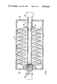
- FIG. 1 is a schematic plan view of a rotary processor in accordance with the invention
- FIG. 2 is a view, partially in section, of a shaft and selected affixed components
- FIG. 3 is a top view of a terminal block additionally showing an angular orientation of the block relative to the shaft axial centerline;
- FIG. 4 is a simplified perspective view of staggered terminal blocks mounted on a shaft segment
- FIG. 5 is a simplified cross sectional view of terminal blocks mounted on a shaft segment
- FIGS. 6a, 6b and 6c are respectively a bottom, front and section view of a preferred terminal block
- FIGS. 7a, 7b and 7c are respectively a side, top and end view of a terminal block and coil subassembly.
- FIGS. 8a, 8b and 8c are respectively a front, end, and section view of a shaft segment, FIG. 8c being a section taken at 8C--8C of FIG. 8a.
- a rotary processor 10 including a shaft 12 supported by a housing 14.
- the shaft 12 is rotated by a drive 16.
- Mounted to the shaft 12 are a plurality of solid or preferably hollow helical coils 18.
- the coils are affixed to the shaft through terminal blocks 20 mounted at the end of each coil 18.
- a fluid flow path is established serially among a reservoir 22, an inlet conduit 24, the interior of the shaft 12, the coils 18, back through the shaft to an outlet conduit 26 and to the reservoir 22.
- the reservoir 22 preferably includes a pump and heat exchange means to cool or heat the circulated fluid.
- the housing 14 has an inlet 28 and an outlet 30.
- the inlet and outlet can be variously positioned, for example, including a top inlet and a bottom or side outlet.
- the drive 16 is coupled to the shaft 12 and upon rotation of the shaft 12 a fluid medium in the housing 14 is conveyed from the volume at the inlet 28 toward the volume at the outlet 30.
- the shaft 12 includes a plurality of segments joined to one another such as through welds 32. Included are a solid drive shaft segment 34, a first polygonal segment 36, a central segment 38, a second polygonal segment 40, and a gland shaft segment 42.
- the drive shaft segment 34, central segment 38 and gland shaft segment 42 are all of circular cross section, the central segment 38 and gland shaft segment 42 being of hollow tubular construction.
- the polygonal segments are hollow, are of polygonal exterior cross section having a plurality of edges 44, and preferably form regular polygons.
- a tubular guide 46 and barrier 48 are utilized at the gland segment 42 end of the shaft to direct cooling fluid flow within the shaft 12.
- the edges 44 of the first segment 36 are angularly offset or rotated with respect to the respective edges 44 of the second segment 40, there being six edges 44 on each segment in the exemplary processor 10.
- the number of terminal blocks 20 affixed to each segment is the same as the number of edges of that segment, as well as the same as the number of coils 18 of the processor 10.
- the terminal blocks 20 are removably affixed and sealed to the segments.
- Each block 20 includes four penetrations 50 through which removable fasteners such as bolts 52 pass.
- a receptacle 54 is formed in each edge 44 to receive a sealing gasket 56.
- the receptacles 54 can also or alternatively receive extensions 55 of the terminal blocks.
- the edges 44 of the polygonal segments and the bottoms of the terminal block are flat surfaces which are highly machined so that, when bolted together, a good metal to metal contact is made.
- An aperture 58 extends from an interior portion 60 of each polygonal segment 36, 40 to each edge 44.
- the terminal blocks 20 each have a passage 62 therethrough terminating at one end at a face 66 of the block 20.
- the end of the passage 62 at the bottom of the block is aligned with and in direct fluid communication with a respective aperture 58.
- the end of the passage 62 at the face 66 of the block 20 receives an end 68 of a respective coil 18.
- the end of the passage 62 receiving the end of the coil preferably includes an enlarged countersink 67.
- the ends 68 of the coils are straightened for positioning within the aperatures 58. In FIG. 5 the transition between the normal helical curve and the straightened ends 68 is highly exaggerated.
- the coils 18 are welded to the terminal blocks 20 as shown at numeral 67 of FIG. 5.
- FIGS. 7a, 7b, 7c are formed comprising a coil 18 and the terminal blocks 20 welded to the ends 68 of the coil.
- the terminal blocks 20 can readily be bolted and secured to the polygonal segments 36, 40.
- the exemplary processor has six subassemblies 70.
- each of the coils 18, and also the subassemblies 70 are preferably identical and hence interchangeable.
- the terminal blocks 20 are staggered along the polygonal segments as shown best in FIG. 4 where the centerline c through a circular end of the passage 62 at the face 66 of a block is spaced a distance d from the equivalent centerline of the next consecutive block 20.
- This axial staggering is also shown i FIG. 8a.
- This staggering or spacing along the axial length of the shaft 12 provides better accessibility for fabrication and repair.
- the preferred staggering distance d between blocks of consecutive subassemblies 70 is equal to the pitch p of the helical coils divided by the number of subassemblies 70. This spacing provides good conveyance characteristics and, particularly for subassemblies with inherently small clearances, allows nesting among consecutive coils.
- the height of the terminal blocks 20 and the spacing from the shaft of the end of the passage 62 which receives the coil 18 is such that the coils are maintained a preselected distance from the shaft.
- the coil enters the terminal block at the low point of its helix, that is, the point closest to the shaft.
- the processor can also include clamps along the central segment 38 for additional support of the coils.
- the exterior of the polygonal sections, for example the across flats dimension of a regular polygon, is larger than the diameter of the central segment to provide spacing between the coils and the shaft. The spacing can be established to minimize the potential for buildup of the material being processed between the coils and the shaft.
- the side face 66 of a rectangular terminal block 20 receiving the end of the respective coil is rotated slightly with respect to the axis 72 of the shaft and the parallel axis 74 of the coil.
- the rotated relation is also apparent in FIGS. 7a, 7b and 7c. With this orientation the coil enters the block at a right angle to the face 66.
- the rotated configuration is critical toward alleviating stresses induced in the coil during fabrication and operation and to ensure a solid weld between the block and coil.
- the angle of rotation 76 is equal to the helix angle and will for most processors vary between approximately 8 degrees and 22 degrees, preferably being approximately eight degrees.
- the rotated configuration causes an offset 78 (FIG. 2) between a centerline 80 of the aperture 58 through the polygonal segment and the centerline of the end of the passage 62 of the terminal block 20 receiving the coil 18. It is critical that the offset 78 be accounted for in the initial design and sizing of a given processor since the coils 18 enter a front face 82 of one terminal block 20 and enter a rear face 84 of the other respective terminal block 20.
- the actual length of the coil 18 between the blocks 20 is equal to the distance between respective apertures 58 minus twice the offset distance 78.
- the offset distance is relatively small, being approximately two-tenths of an inch in an exemplary processor having coils 18 of an outside diameter of eleven inches, incorporation of the distance is critical in order to minimize induced stresses.
- the straightened ends of the coils 18 extend into the respective terminal blocks 20 approximately one-quarter inch.
- the helix angle 76 is 8°34' ⁇ 30'.
- the rotational angle shown at reference numeral 88 in FIG. 7c, is 14° - 6' in the exemplary processor.
- This angular offset is preferably between ten (10) and eighteen (18) degrees. This angle is determined among several considerations and is the manner by which the helical coil is made most closely to align at ninety degrees to the manifold block. If the terminal block were infinitely thin along a line between the center of the polygonal section and the axis of the corresponding coil, the coil would approach that infinitely thin line at ninety degrees.
- the approach angle is other than ninety degrees.
- the rotation of the polygonal segments accounts for this angular difference.
- this ninety degree approach relationship can also be achieved by moving the block "back and away" from the approach of the coil.
- the amount of area available to move the block is limited by the size of the corresponding edge 44. A combination of these considerations can also be used.
Abstract
Description
Claims (4)
Priority Applications (1)
| Application Number | Priority Date | Filing Date | Title |
|---|---|---|---|
| US06/658,723 US4596286A (en) | 1984-10-09 | 1984-10-09 | Rotary processor |
Applications Claiming Priority (1)
| Application Number | Priority Date | Filing Date | Title |
|---|---|---|---|
| US06/658,723 US4596286A (en) | 1984-10-09 | 1984-10-09 | Rotary processor |
Publications (1)
| Publication Number | Publication Date |
|---|---|
| US4596286A true US4596286A (en) | 1986-06-24 |
Family
ID=24642411
Family Applications (1)
| Application Number | Title | Priority Date | Filing Date |
|---|---|---|---|
| US06/658,723 Expired - Fee Related US4596286A (en) | 1984-10-09 | 1984-10-09 | Rotary processor |
Country Status (1)
| Country | Link |
|---|---|
| US (1) | US4596286A (en) |
Cited By (8)
| Publication number | Priority date | Publication date | Assignee | Title |
|---|---|---|---|---|
| WO1989004448A1 (en) * | 1987-10-30 | 1989-05-18 | Berwind Corporation | Heat exchanger |
| US4893672A (en) * | 1986-08-21 | 1990-01-16 | Bader Emil E | Counter-flow heat exchanger with helical tube bundle |
| US5802961A (en) * | 1994-04-15 | 1998-09-08 | Fmc Corporation | Methods and apparatus for particulate heat exchange and transfer |
| US6122954A (en) * | 1996-07-11 | 2000-09-26 | Femtometrics, Inc. | High sensitivity instrument to measure NVR in fluid |
| WO2005085521A1 (en) * | 2004-03-08 | 2005-09-15 | Lars Vedsted | A method and a product for heating or cooling of foodstuffs |
| US20120079951A1 (en) * | 2003-10-08 | 2012-04-05 | Kraft Foods Global Brands Llc | Apparatus and Method for Surface Treatment of a Food Product |
| US20140014299A1 (en) * | 2012-07-12 | 2014-01-16 | Aisin Seiki Kabushiki Kaisha | Chemical heat storage device |
| WO2021152640A1 (en) * | 2020-01-28 | 2021-08-05 | Lambhusasund Ehf. | Multi-piping spiral-pump for treating food items |
Citations (8)
| Publication number | Priority date | Publication date | Assignee | Title |
|---|---|---|---|---|
| US1088113A (en) * | 1913-11-10 | 1914-02-24 | Creamery Package Mfg Co | Apparatus for treating milk and cream or the like. |
| GB313780A (en) * | 1928-07-11 | 1929-06-20 | Charles Mcneil | Improvements relating to heat-exchanging devices |
| GB469771A (en) * | 1936-02-04 | 1937-08-03 | Barclays Bank Ltd | Improvements in sugar crystallizing and like apparatus |
| US2271862A (en) * | 1940-10-14 | 1942-02-03 | Newel F Hodgdon | Pasteurizing device |
| US2458440A (en) * | 1946-04-24 | 1949-01-04 | Turl Iron And Car Company Inc | Crystallizer |
| US2890865A (en) * | 1956-02-06 | 1959-06-16 | Von Kohorn Internat Corp | Chemical treating apparatus |
| US3009683A (en) * | 1958-11-07 | 1961-11-21 | Western States Machine Co | Sugar mingler shaft mounting |
| US4482253A (en) * | 1983-03-28 | 1984-11-13 | Joy Manufacturing Company | Rotary material processor |
-
1984
- 1984-10-09 US US06/658,723 patent/US4596286A/en not_active Expired - Fee Related
Patent Citations (8)
| Publication number | Priority date | Publication date | Assignee | Title |
|---|---|---|---|---|
| US1088113A (en) * | 1913-11-10 | 1914-02-24 | Creamery Package Mfg Co | Apparatus for treating milk and cream or the like. |
| GB313780A (en) * | 1928-07-11 | 1929-06-20 | Charles Mcneil | Improvements relating to heat-exchanging devices |
| GB469771A (en) * | 1936-02-04 | 1937-08-03 | Barclays Bank Ltd | Improvements in sugar crystallizing and like apparatus |
| US2271862A (en) * | 1940-10-14 | 1942-02-03 | Newel F Hodgdon | Pasteurizing device |
| US2458440A (en) * | 1946-04-24 | 1949-01-04 | Turl Iron And Car Company Inc | Crystallizer |
| US2890865A (en) * | 1956-02-06 | 1959-06-16 | Von Kohorn Internat Corp | Chemical treating apparatus |
| US3009683A (en) * | 1958-11-07 | 1961-11-21 | Western States Machine Co | Sugar mingler shaft mounting |
| US4482253A (en) * | 1983-03-28 | 1984-11-13 | Joy Manufacturing Company | Rotary material processor |
Cited By (14)
| Publication number | Priority date | Publication date | Assignee | Title |
|---|---|---|---|---|
| US4893672A (en) * | 1986-08-21 | 1990-01-16 | Bader Emil E | Counter-flow heat exchanger with helical tube bundle |
| WO1989004448A1 (en) * | 1987-10-30 | 1989-05-18 | Berwind Corporation | Heat exchanger |
| US4856580A (en) * | 1987-10-30 | 1989-08-15 | Berwind Corporation | Heat exchanger |
| US5802961A (en) * | 1994-04-15 | 1998-09-08 | Fmc Corporation | Methods and apparatus for particulate heat exchange and transfer |
| US6122954A (en) * | 1996-07-11 | 2000-09-26 | Femtometrics, Inc. | High sensitivity instrument to measure NVR in fluid |
| US20120079951A1 (en) * | 2003-10-08 | 2012-04-05 | Kraft Foods Global Brands Llc | Apparatus and Method for Surface Treatment of a Food Product |
| US20080271610A1 (en) * | 2004-03-08 | 2008-11-06 | Laitram, L.L.C. | Method and a Product for Heating or Cooling of Foodstuffs |
| US7784397B2 (en) | 2004-03-08 | 2010-08-31 | Laitram, L.L.C. | Method and apparatus for heating or cooling of foodstuffs |
| WO2005085521A1 (en) * | 2004-03-08 | 2005-09-15 | Lars Vedsted | A method and a product for heating or cooling of foodstuffs |
| US20140014299A1 (en) * | 2012-07-12 | 2014-01-16 | Aisin Seiki Kabushiki Kaisha | Chemical heat storage device |
| CN103542752A (en) * | 2012-07-12 | 2014-01-29 | 爱信精机株式会社 | Chemical heat storage device |
| US9714793B2 (en) * | 2012-07-12 | 2017-07-25 | Aisin Seiki Kabushiki Kaisha | Chemical heat storage device including rotatable heat storage material accommodation unit |
| WO2021152640A1 (en) * | 2020-01-28 | 2021-08-05 | Lambhusasund Ehf. | Multi-piping spiral-pump for treating food items |
| CN115279192A (en) * | 2020-01-28 | 2022-11-01 | 兰博胡萨桑德有限公司 | Multi-pipe screw pump for processing food |
Similar Documents
| Publication | Publication Date | Title |
|---|---|---|
| US4596286A (en) | Rotary processor | |
| DE3740295C2 (en) | ||
| US5379952A (en) | Agitator mill | |
| EP1061319B1 (en) | Fluid conveying tube and use of the same in a vehicle cooler | |
| DE69530385T2 (en) | COOLING DEVICE | |
| US4510991A (en) | Heat exchanger and fan motor in a front wheel drive vehicle | |
| US3777650A (en) | Air distributor | |
| JPH09506568A (en) | Multi-screw extruder compounder with modular mixing elements | |
| JPS5918525B2 (en) | turbine casing | |
| EP1719914B1 (en) | Centrifugal pump with magnetic coupling | |
| AU2880892A (en) | Plate type heat exchanger | |
| US5692831A (en) | High speed combined mixing and transport tool | |
| US4482253A (en) | Rotary material processor | |
| US4642026A (en) | Centrifugal compressor with adjustable diffuser | |
| EP0117820B1 (en) | Segmental baffle high performance shell and tube heat exchanger | |
| US4236833A (en) | Screw machine for processing materials of solid, pasty and liquid consistency | |
| EP0656479B1 (en) | One stage vane compressor | |
| EP0074514B1 (en) | Arrangement of a cooler and a motor having a ventilator arranged on its shaft, especially for a screw compressor installation | |
| CN2108078U (en) | Internal cooling type screw conveyer | |
| US3478820A (en) | Cooling apparatus for high heat fluxes | |
| CN1898480A (en) | Hydrodynamic clutch | |
| USRE32169E (en) | Thermal exchanger | |
| IE50173B1 (en) | Propulsion apparatus | |
| EP0270181B1 (en) | A rotary distribution group for hydraulic motors with orbiting sealing surfaces | |
| US4451092A (en) | Cutting roller |
Legal Events
| Date | Code | Title | Description |
|---|---|---|---|
| AS | Assignment |
Owner name: JOY MANUFACTURING COMPANY 301 GRANT STREET, PITTSB Free format text: ASSIGNMENT OF ASSIGNORS INTEREST.;ASSIGNOR:STETLER, GARY W.;REEL/FRAME:004324/0781 Effective date: 19840926 |
|
| AS | Assignment |
Owner name: JOY TECHNOLOGIES INC., 301 GRANT STREET, PITTSBURG Free format text: ASSIGNMENT OF ASSIGNORS INTEREST.;ASSIGNOR:JOY MANUFACTURING COMPANY, A CORP. OF PA;REEL/FRAME:004880/0430 Effective date: 19870529 Owner name: JOY TECHNOLOGIES INC., A CORP. OF DE.,PENNSYLVANIA Free format text: ASSIGNMENT OF ASSIGNORS INTEREST;ASSIGNOR:JOY MANUFACTURING COMPANY, A CORP. OF PA;REEL/FRAME:004880/0430 Effective date: 19870529 |
|
| AS | Assignment |
Owner name: JOY TECHNOLOGIES INC., 301 GRANT STREET, PITTSBURG Free format text: ASSIGNMENT OF ASSIGNORS INTEREST.;ASSIGNOR:JOY MANUFACTURING COMPANY, A CORP. OF PA;REEL/FRAME:004747/0261 Effective date: 19870626 Owner name: CITIBANK, N.A., 641 LEXINGTON AVENUE, NEW YORK, NE Free format text: ASSIGNMENT OF ASSIGNORS INTEREST.;ASSIGNOR:JOY TECHNOLOGIES INC., 301 GRANT STREET, PITTSBURGH, PA 15219, A DE CORP.;REEL/FRAME:004846/0025 Effective date: 19870626 Owner name: CITIBANK, N.A.,NEW YORK Free format text: ASSIGNMENT OF ASSIGNORS INTEREST;ASSIGNOR:JOY TECHNOLOGIES INC., 301 GRANT STREET, PITTSBURGH, PA 15219, A DE CORP.;REEL/FRAME:004846/0025 Effective date: 19870626 Owner name: JOY TECHNOLOGIES INC., PENNSYLVANIA Free format text: ASSIGNMENT OF ASSIGNORS INTEREST;ASSIGNOR:JOY MANUFACTURING COMPANY, A CORP. OF PA;REEL/FRAME:004747/0261 Effective date: 19870626 |
|
| AS | Assignment |
Owner name: JOY MANUFACTURING COMPANY Free format text: ASSIGNMENT OF ASSIGNORS INTEREST. EFFECTIVE DATE;ASSIGNOR:JOY TECHNOLOGIES INCL., (A DE CORP.);REEL/FRAME:004827/0367 Effective date: 19870626 Owner name: JOY MANUFACTURING COMPANY,STATELESS Free format text: ASSIGNMENT OF ASSIGNORS INTEREST;ASSIGNOR:JOY TECHNOLOGIES INCL., (A DE CORP.);REEL/FRAME:004827/0367 Effective date: 19870626 |
|
| AS | Assignment |
Owner name: CITICORP NORTH AMERICA, INC. Free format text: SECURITY INTEREST;ASSIGNOR:DENVER EQUIPMENT COMPANY;REEL/FRAME:004846/0250 Effective date: 19880225 Owner name: COLGATE-PALMOLIVE COMPANY, 300 PARK AVENUE, NEW YO Free format text: SECURITY INTEREST;ASSIGNOR:MALIHI, FARROKH B.;REEL/FRAME:004846/0264 Effective date: 19880212 Owner name: COLGATE-PALMOLIVE COMPANY,NEW YORK Free format text: SECURITY INTEREST;ASSIGNOR:MALIHI, FARROKH B.;REEL/FRAME:004846/0264 Effective date: 19880212 |
|
| AS | Assignment |
Owner name: CITIBANK, N.A., 641 LEXINGTON AVENUE, NEW YORK, NE Free format text: SECURITY INTEREST;ASSIGNOR:JOY TECHNOLOGIES INC.,;REEL/FRAME:004936/0730 Effective date: 19870626 |
|
| AS | Assignment |
Owner name: JOY TECHNOLOGIES INC., A CORP OF DE, PENNSYLVANIA Free format text: RELEASED BY SECURED PARTY;ASSIGNORS:MC CARTNEY, DEREK L.;ARCHIBALD, JOHN H.;REEL/FRAME:005237/0152 Effective date: 19870626 |
|
| AS | Assignment |
Owner name: JOY TECHNOLOGIES, INC., A CORP OF DE Free format text: RELEASED BY SECURED PARTY;ASSIGNOR:CITIBANK N.A.;REEL/FRAME:005237/0187 Effective date: 19891011 |
|
| AS | Assignment |
Owner name: BARCLAYS BUSINESS CREDIT, INC., 1999 HARRISON STRE Free format text: SECURITY INTEREST;ASSIGNORS:DENVER TECHNOLOGIES, INC., A DE CORP.;DENVER EQUIPEMENT COMPANY, A DE CORP.;AUTOMETRICS CO., D/B/A DENVER AUTOMETRICS, INC., A CO CORP.;AND OTHERS;REEL/FRAME:005261/0439 Effective date: 19891130 Owner name: DENVER EQUIPMENT COMPANY, A DE CORP. Free format text: RELEASED BY SECURED PARTY;ASSIGNOR:CITICORP NORTH AMERICA, INC.;REEL/FRAME:005261/0018 Effective date: 19891201 |
|
| REMI | Maintenance fee reminder mailed | ||
| LAPS | Lapse for failure to pay maintenance fees | ||
| STCH | Information on status: patent discontinuation |
Free format text: PATENT EXPIRED DUE TO NONPAYMENT OF MAINTENANCE FEES UNDER 37 CFR 1.362 |
|
| FP | Lapsed due to failure to pay maintenance fee |
Effective date: 19900624 |