US4588919A - Low-pressure alkali metal vapor discharge lamp with arc tube gettering - Google Patents
Low-pressure alkali metal vapor discharge lamp with arc tube gettering Download PDFInfo
- Publication number
- US4588919A US4588919A US06/597,977 US59797784A US4588919A US 4588919 A US4588919 A US 4588919A US 59797784 A US59797784 A US 59797784A US 4588919 A US4588919 A US 4588919A
- Authority
- US
- United States
- Prior art keywords
- getter
- envelope
- electrodes
- lamp
- discharge
- Prior art date
- Legal status (The legal status is an assumption and is not a legal conclusion. Google has not performed a legal analysis and makes no representation as to the accuracy of the status listed.)
- Expired - Fee Related
Links
- 229910052783 alkali metal Inorganic materials 0.000 title claims abstract description 11
- 150000001340 alkali metals Chemical class 0.000 title claims abstract description 11
- 238000005247 gettering Methods 0.000 title claims description 9
- 239000007789 gas Substances 0.000 claims abstract description 13
- 229910052751 metal Inorganic materials 0.000 claims description 24
- 239000002184 metal Substances 0.000 claims description 24
- 239000004020 conductor Substances 0.000 claims description 3
- 238000010891 electric arc Methods 0.000 claims description 3
- 229910000287 alkaline earth metal oxide Inorganic materials 0.000 claims description 2
- 239000011261 inert gas Substances 0.000 claims description 2
- 239000000463 material Substances 0.000 abstract description 5
- 239000000956 alloy Substances 0.000 description 7
- 229910045601 alloy Inorganic materials 0.000 description 7
- 239000011734 sodium Substances 0.000 description 7
- 238000001704 evaporation Methods 0.000 description 6
- FVAUCKIRQBBSSJ-UHFFFAOYSA-M sodium iodide Chemical compound [Na+].[I-] FVAUCKIRQBBSSJ-UHFFFAOYSA-M 0.000 description 6
- CURLTUGMZLYLDI-UHFFFAOYSA-N Carbon dioxide Chemical compound O=C=O CURLTUGMZLYLDI-UHFFFAOYSA-N 0.000 description 5
- DGAQECJNVWCQMB-PUAWFVPOSA-M Ilexoside XXIX Chemical compound C[C@@H]1CC[C@@]2(CC[C@@]3(C(=CC[C@H]4[C@]3(CC[C@@H]5[C@@]4(CC[C@@H](C5(C)C)OS(=O)(=O)[O-])C)C)[C@@H]2[C@]1(C)O)C)C(=O)O[C@H]6[C@@H]([C@H]([C@@H]([C@H](O6)CO)O)O)O.[Na+] DGAQECJNVWCQMB-PUAWFVPOSA-M 0.000 description 5
- 239000000843 powder Substances 0.000 description 5
- 229910052708 sodium Inorganic materials 0.000 description 5
- PXHVJJICTQNCMI-UHFFFAOYSA-N Nickel Chemical compound [Ni] PXHVJJICTQNCMI-UHFFFAOYSA-N 0.000 description 4
- 238000010438 heat treatment Methods 0.000 description 4
- 239000000203 mixture Substances 0.000 description 4
- 229910052788 barium Inorganic materials 0.000 description 3
- DSAJWYNOEDNPEQ-UHFFFAOYSA-N barium atom Chemical compound [Ba] DSAJWYNOEDNPEQ-UHFFFAOYSA-N 0.000 description 3
- 229910002092 carbon dioxide Inorganic materials 0.000 description 3
- 150000004649 carbonic acid derivatives Chemical class 0.000 description 3
- 230000008021 deposition Effects 0.000 description 3
- 239000000126 substance Substances 0.000 description 3
- XKRFYHLGVUSROY-UHFFFAOYSA-N Argon Chemical compound [Ar] XKRFYHLGVUSROY-UHFFFAOYSA-N 0.000 description 2
- IJGRMHOSHXDMSA-UHFFFAOYSA-N Atomic nitrogen Chemical compound N#N IJGRMHOSHXDMSA-UHFFFAOYSA-N 0.000 description 2
- XEEYBQQBJWHFJM-UHFFFAOYSA-N Iron Chemical compound [Fe] XEEYBQQBJWHFJM-UHFFFAOYSA-N 0.000 description 2
- ZLMJMSJWJFRBEC-UHFFFAOYSA-N Potassium Chemical compound [K] ZLMJMSJWJFRBEC-UHFFFAOYSA-N 0.000 description 2
- 229910052782 aluminium Inorganic materials 0.000 description 2
- XAGFODPZIPBFFR-UHFFFAOYSA-N aluminium Chemical compound [Al] XAGFODPZIPBFFR-UHFFFAOYSA-N 0.000 description 2
- QVGXLLKOCUKJST-UHFFFAOYSA-N atomic oxygen Chemical compound [O] QVGXLLKOCUKJST-UHFFFAOYSA-N 0.000 description 2
- 239000001569 carbon dioxide Substances 0.000 description 2
- 229910002091 carbon monoxide Inorganic materials 0.000 description 2
- 238000006243 chemical reaction Methods 0.000 description 2
- 150000004679 hydroxides Chemical class 0.000 description 2
- 239000012535 impurity Substances 0.000 description 2
- 238000004519 manufacturing process Methods 0.000 description 2
- 229910052759 nickel Inorganic materials 0.000 description 2
- 229910052760 oxygen Inorganic materials 0.000 description 2
- 239000001301 oxygen Substances 0.000 description 2
- 229910052700 potassium Inorganic materials 0.000 description 2
- 239000011591 potassium Substances 0.000 description 2
- 235000009518 sodium iodide Nutrition 0.000 description 2
- XLYOFNOQVPJJNP-UHFFFAOYSA-N water Substances O XLYOFNOQVPJJNP-UHFFFAOYSA-N 0.000 description 2
- 229910001868 water Inorganic materials 0.000 description 2
- ZSLUVFAKFWKJRC-IGMARMGPSA-N 232Th Chemical compound [232Th] ZSLUVFAKFWKJRC-IGMARMGPSA-N 0.000 description 1
- 229910016015 BaAl4 Inorganic materials 0.000 description 1
- OYPRJOBELJOOCE-UHFFFAOYSA-N Calcium Chemical compound [Ca] OYPRJOBELJOOCE-UHFFFAOYSA-N 0.000 description 1
- UGFAIRIUMAVXCW-UHFFFAOYSA-N Carbon monoxide Chemical compound [O+]#[C-] UGFAIRIUMAVXCW-UHFFFAOYSA-N 0.000 description 1
- 229910003550 H2 O Inorganic materials 0.000 description 1
- FYYHWMGAXLPEAU-UHFFFAOYSA-N Magnesium Chemical compound [Mg] FYYHWMGAXLPEAU-UHFFFAOYSA-N 0.000 description 1
- NPYPAHLBTDXSSS-UHFFFAOYSA-N Potassium ion Chemical compound [K+] NPYPAHLBTDXSSS-UHFFFAOYSA-N 0.000 description 1
- NPXOKRUENSOPAO-UHFFFAOYSA-N Raney nickel Chemical compound [Al].[Ni] NPXOKRUENSOPAO-UHFFFAOYSA-N 0.000 description 1
- FKNQFGJONOIPTF-UHFFFAOYSA-N Sodium cation Chemical compound [Na+] FKNQFGJONOIPTF-UHFFFAOYSA-N 0.000 description 1
- 229910052776 Thorium Inorganic materials 0.000 description 1
- RTAQQCXQSZGOHL-UHFFFAOYSA-N Titanium Chemical compound [Ti] RTAQQCXQSZGOHL-UHFFFAOYSA-N 0.000 description 1
- QCWXUUIWCKQGHC-UHFFFAOYSA-N Zirconium Chemical compound [Zr] QCWXUUIWCKQGHC-UHFFFAOYSA-N 0.000 description 1
- 239000004411 aluminium Substances 0.000 description 1
- 229910052786 argon Inorganic materials 0.000 description 1
- 150000001553 barium compounds Chemical class 0.000 description 1
- 229910052791 calcium Inorganic materials 0.000 description 1
- 239000011575 calcium Substances 0.000 description 1
- 230000000052 comparative effect Effects 0.000 description 1
- 150000001875 compounds Chemical class 0.000 description 1
- 230000007423 decrease Effects 0.000 description 1
- 238000006073 displacement reaction Methods 0.000 description 1
- 238000002474 experimental method Methods 0.000 description 1
- 239000001257 hydrogen Substances 0.000 description 1
- 229910052739 hydrogen Inorganic materials 0.000 description 1
- 125000004435 hydrogen atom Chemical class [H]* 0.000 description 1
- XMBWDFGMSWQBCA-UHFFFAOYSA-N hydrogen iodide Chemical compound I XMBWDFGMSWQBCA-UHFFFAOYSA-N 0.000 description 1
- 150000002500 ions Chemical class 0.000 description 1
- 229910052742 iron Inorganic materials 0.000 description 1
- 229910052749 magnesium Inorganic materials 0.000 description 1
- 239000011777 magnesium Substances 0.000 description 1
- 229910052754 neon Inorganic materials 0.000 description 1
- GKAOGPIIYCISHV-UHFFFAOYSA-N neon atom Chemical compound [Ne] GKAOGPIIYCISHV-UHFFFAOYSA-N 0.000 description 1
- ZSJFLDUTBDIFLJ-UHFFFAOYSA-N nickel zirconium Chemical compound [Ni].[Zr] ZSJFLDUTBDIFLJ-UHFFFAOYSA-N 0.000 description 1
- 229910052757 nitrogen Inorganic materials 0.000 description 1
- 229910001414 potassium ion Inorganic materials 0.000 description 1
- 230000009257 reactivity Effects 0.000 description 1
- 229910001415 sodium ion Inorganic materials 0.000 description 1
- 229910052712 strontium Inorganic materials 0.000 description 1
- CIOAGBVUUVVLOB-UHFFFAOYSA-N strontium atom Chemical compound [Sr] CIOAGBVUUVVLOB-UHFFFAOYSA-N 0.000 description 1
- 239000010936 titanium Substances 0.000 description 1
- 229910052719 titanium Inorganic materials 0.000 description 1
- 229910052726 zirconium Inorganic materials 0.000 description 1
Images
Classifications
-
- H—ELECTRICITY
- H01—ELECTRIC ELEMENTS
- H01J—ELECTRIC DISCHARGE TUBES OR DISCHARGE LAMPS
- H01J61/00—Gas-discharge or vapour-discharge lamps
- H01J61/02—Details
- H01J61/24—Means for obtaining or maintaining the desired pressure within the vessel
- H01J61/26—Means for absorbing or adsorbing gas, e.g. by gettering; Means for preventing blackening of the envelope
Definitions
- the invention relates to a low-pressure alkali metal vapor discharge lamp provided with a discharge envelope or arc tube which is arranged in an evacuated outer bulb, electrodes arranged in the arc tube and incorporating an emitter containing an alkaline earth metal oxide, and a getter in the evacuated space.
- an alkali metal vapor discharge lamp refers to one in which, in an operating condition, the arc discharge current is carried primarily by an alkali metal vapor rather than by an inert gas.
- a low-pressure sodium vapor lamp of this kind is known from German Pat. No. 913,468.
- the known lamp has a gettering metal layer deposited on a wall in the evacuated space between the outer bulb and the discharge envelope.
- This gettering metal layer serves to bind residual gases and gases released during the life of the lamp.
- gases are: hydrogen, oxygen, nitrogen, water vapour, carbon monoxide and carbon dioxide.
- the gettering metal layer may consist of a metal, such as barium, calcium, strontium, or magnesium.
- the metal layer is obtained by heating an open holder provided with such a metal after the outer bulb has been evacuated, as a result of which the metal evaporates for the major part and is deposited on a wall opposite to the opening of the holder.
- the getter metal is present in the holder in the form of an alloy with, for example, aluminum.
- the gettering metal can be manipulated more readily in air.
- the alloy can be mixed with a metal powder, such as nickel, iron, titanium or thorium powder, for example with an equal quantity by weight of such a powder.
- a powder enters into an exothermal reaction with the alloy upon heating, as a result of which the getter metal is released and evaporated more rapidly.
- a part of the gettering metal remains in the holder, generally as a compound with, for example, oxygen or with the metal with which the getter metal was provided as an alloy.
- a holder with a non-evaporating getter for example, a metal strip coated with zirconium aluminium or zirconium nickel, may be present in the evacuated space.
- this envelope Before the discharge envelope is sealed, this envelope is evacuated, while the electrodes are heated in order to release absorbed gases therefrom. Carbon dioxide may be produced at this time if the emitter is provided on or in the electrode in the form of one or more carbonates, or water may be produced if the emitter is provided in the form of a hydroxide. Subsequently, the discharge envelope is provided with its gas filling and sealed.
- lamps have a higher ignition voltage if the electrodes are heated during the manufacturing process only to a temperature at which just no loss of emitter occurs.
- the invention has for its object to provide a low-pressure alkali metal vapor discharge lamp which ignites at a comparatively low voltage, at the same time that any loss of emitter material of the electrodes is effectively avoided.
- a getter for di- and triatomic gases such as H 2 , O 2 , N 2 , H 2 O, CO and CO 2
- a getter holder arranged in the discharge envelope.
- the getter may be provided in the discharge envelope in a form which is common practice for use in the outer bulb; namely an open holder provided with the getter, with an alloy of the getter, or with an alloy of the getter mixed with a metal powder which enters into an exothermal reaction with the alloy.
- a holder with a non-evaporating getter may be used.
- the discharge envelope is evacuated and the electrodes are heated in order to desorb gases therefrom and, as the case may be, to form the emitter from, for example, one or more carbonates and/or one or more hydroxides.
- the filling is provided and the discharge envelope is sealed.
- the getter metal can evaporate for the major part from its holder and deposit opposite to the holder on the inner side of the wall of the discharge envelope.
- this getter is activated as impurities at the getter surface difuse inwards due to the heating of the getter by the energy dissipated in the envelope. It is alternatively possible, however, to heat the getter holder inductively and consequently to evaporate and to activate the getter, respectively.
- the getter holder for example an open annular getter or a metal strip, can be arranged in the proximity of an electrode, for example secured to a current-supply conductor to an electrode.
- the getter holder is situated in an electrode chamber.
- the holder then reaches a comparatively high temperature during operation, as a result of which the getter can be caused to be evaporated or activated.
- the holder of an evaporating getter can then be so directed that the deposition of the getter metal on the wall of the discharge envelope does not hinder the emanation of the light generated during operation.
- the use of an evaporating getter such as barium, has the advantage of a getter of high reactivity and a large reactive surface area.
- the electrodes were heated to approximately 1250° C., whereby deposition of emitter material on the wall of the discharge envelope was found.
- the electrodes were heated in the same manner as the electrodes of the first series.
- the discharge envelope near each of the electrodes, there was mounted an open annular holder filled with 4.5 mg of a mixture of equal parts by weight of BaAl 4 and nickel.
- the getter holder was heated inductively and the getter metal evaporated, so that this metal deposited opposite the opening of the holder on the wall of the discharge envelope.
- the lamps of the second and the third series were otherwise identical to those of the first series.
- a discharge envelope or arc tube 2 provided with an ionizable-metal-vapor-containing gas filling is arranged in an evacuated outer bulb 2.
- Current-supply conductors 3 extend from a lamp cap 4 through the wall of the discharge envelope 1 to electrodes 5 arranged in the discharge envelope.
- the outer bulb 2 accommodates holders 6 from which a gettering metal layer 7 is deposited on the wall of the outer bulb.
- a respective open holder 8 is mounted in the discharge envelope and a gettering metal layer deposited on the wall of the discharge envelope 1 is situated opposite to this holder.
- the lamp shown is a 35 W low-pressure sodium lamp with a gas filling of approximately 450 mg of Na and a mixture of 99% by volume of neon and 1% by volume of argon at a pressure of 1200 Pa.
- the electrodes have an emitter comprising a mixture of equimolar quantities of BaO, CaO, and SrO obtained from 22 mg of a corresponding mixture of carbonates.
- the open holders 6 and 8 are annular getters from which barium has evaporated. This getter material has deposited as layers 7 and 9, respectively, on the wall of the outer bulb 2 and of the discharge envelope 1, respectively.
- the holders contain a residue of mainly aluminum-nickel, and a small quantity of barium compound.
Landscapes
- Discharge Lamp (AREA)
- Vessels And Coating Films For Discharge Lamps (AREA)
Abstract
A low-pressure alkali metal vapor discharge lamp has a getter for bi- and triatomic gases and a getter holder in the arc tube near at least one electrode. The electrodes need be heated less strongly during evacuation of the prior to final dosing, as a result of which no emitter material of the electrodes is lost. The ignition voltage is considerably lower than that of conventional lamps without a getter.
Description
The invention relates to a low-pressure alkali metal vapor discharge lamp provided with a discharge envelope or arc tube which is arranged in an evacuated outer bulb, electrodes arranged in the arc tube and incorporating an emitter containing an alkaline earth metal oxide, and a getter in the evacuated space. As used hereinafter, an alkali metal vapor discharge lamp refers to one in which, in an operating condition, the arc discharge current is carried primarily by an alkali metal vapor rather than by an inert gas. A low-pressure sodium vapor lamp of this kind is known from German Pat. No. 913,468.
The known lamp has a gettering metal layer deposited on a wall in the evacuated space between the outer bulb and the discharge envelope. This gettering metal layer serves to bind residual gases and gases released during the life of the lamp. Thus a high vacuum is maintained which minimises thermal losses which would otherwise result from heat conduction by these gases. Examples of such gases are: hydrogen, oxygen, nitrogen, water vapour, carbon monoxide and carbon dioxide.
The gettering metal layer may consist of a metal, such as barium, calcium, strontium, or magnesium. The metal layer is obtained by heating an open holder provided with such a metal after the outer bulb has been evacuated, as a result of which the metal evaporates for the major part and is deposited on a wall opposite to the opening of the holder.
In general, the getter metal is present in the holder in the form of an alloy with, for example, aluminum. In this form, the gettering metal can be manipulated more readily in air. The alloy can be mixed with a metal powder, such as nickel, iron, titanium or thorium powder, for example with an equal quantity by weight of such a powder. Such a powder enters into an exothermal reaction with the alloy upon heating, as a result of which the getter metal is released and evaporated more rapidly. Mostly, a part of the gettering metal remains in the holder, generally as a compound with, for example, oxygen or with the metal with which the getter metal was provided as an alloy.
Otherwise, a holder with a non-evaporating getter, for example, a metal strip coated with zirconium aluminium or zirconium nickel, may be present in the evacuated space.
Before the discharge envelope is sealed, this envelope is evacuated, while the electrodes are heated in order to release absorbed gases therefrom. Carbon dioxide may be produced at this time if the emitter is provided on or in the electrode in the form of one or more carbonates, or water may be produced if the emitter is provided in the form of a hydroxide. Subsequently, the discharge envelope is provided with its gas filling and sealed.
It has been found that during their heating the electrodes lose a part of the quantity of emitter, which deposits on the wall of the discharge envelope. This loss of a part of the supply of emitter of the electrodes is contrary to the endeavours made to furnish the electrodes with as large a quantity of emitter as possible, in order to prevent the lack of emitter from curtailing the life of a lamp.
It has further been found that lamps have a higher ignition voltage if the electrodes are heated during the manufacturing process only to a temperature at which just no loss of emitter occurs.
An example of a getter-like action in an alkali metal arc tube is shown in British Pat. No. 2,007,423, which describes a low-pressure sodium vapor discharge lamp which contains in the arc tube a substance which binds potassium. This substance, sodium iodide, is not so much a getter as an ion exchanger. Potassium, which is released from the wall of the discharge vessel, enters into a displacement reaction with this substance, in which the sodium ion from the iodide is replaced by a potassium ion and sodium is released (NaI+K→KI+Na).
The invention has for its object to provide a low-pressure alkali metal vapor discharge lamp which ignites at a comparatively low voltage, at the same time that any loss of emitter material of the electrodes is effectively avoided.
According to the invention, in a low-pressure alkali metal vapor discharge lamp a getter for di- and triatomic gases, such as H2, O2, N2, H2 O, CO and CO2, and a getter holder are arranged in the discharge envelope.
The getter may be provided in the discharge envelope in a form which is common practice for use in the outer bulb; namely an open holder provided with the getter, with an alloy of the getter, or with an alloy of the getter mixed with a metal powder which enters into an exothermal reaction with the alloy. Alternatively, a holder with a non-evaporating getter may be used.
During the manufacture of the lamp, the discharge envelope is evacuated and the electrodes are heated in order to desorb gases therefrom and, as the case may be, to form the emitter from, for example, one or more carbonates and/or one or more hydroxides. When the discharge envelope is freed to a large extent from impurities, the filling is provided and the discharge envelope is sealed. In the case an evaporating getter is present, when a discharge is produced for the first time in the discharge envelope, the getter metal can evaporate for the major part from its holder and deposit opposite to the holder on the inner side of the wall of the discharge envelope. In the case a non-evaporating getter is present, this getter is activated as impurities at the getter surface difuse inwards due to the heating of the getter by the energy dissipated in the envelope. It is alternatively possible, however, to heat the getter holder inductively and consequently to evaporate and to activate the getter, respectively.
The getter holder, for example an open annular getter or a metal strip, can be arranged in the proximity of an electrode, for example secured to a current-supply conductor to an electrode. In a preferred embodiment, the getter holder is situated in an electrode chamber. The holder then reaches a comparatively high temperature during operation, as a result of which the getter can be caused to be evaporated or activated. The holder of an evaporating getter can then be so directed that the deposition of the getter metal on the wall of the discharge envelope does not hinder the emanation of the light generated during operation. The use of an evaporating getter, such as barium, has the advantage of a getter of high reactivity and a large reactive surface area.
In comparative experiments with low-pressure sodium vapor discharge lamps which consumed 35 W during operation, the following has been found. Three series of lamps were manufactured: In a first series of lamps, the electrodes were heated stepwise to approximately 1150° C. after the discharge envelope had been evacuated. No deposition of emitter material on the wall of the discharge envelope was then found. Subsequently, the discharge envelope was provided with its gas filling and, after being mounted in an outer bulb, processed to a finished lamp.
In a second series of lamps, on the contrary, the electrodes were heated to approximately 1250° C., whereby deposition of emitter material on the wall of the discharge envelope was found.
In a third series of lamps, the electrodes were heated in the same manner as the electrodes of the first series. In the discharge envelope, near each of the electrodes, there was mounted an open annular holder filled with 4.5 mg of a mixture of equal parts by weight of BaAl4 and nickel. After the discharge envelope had been sealed, the getter holder was heated inductively and the getter metal evaporated, so that this metal deposited opposite the opening of the holder on the wall of the discharge envelope.
The lamps of the second and the third series were otherwise identical to those of the first series.
Across the lamps there was applied a voltage which was increased stepwise by 20 V until the lamps ignited. The lamps of the first series ignited only at 620 V, those of the second series at 580 V and those of the third series at 420 V. It is advantageous that the lamps according to the invention ignite at a relatively low voltage because this results in less emitter consumption. Further, the risk of incidental reject due to an excessively high ignition voltage is thus reduced. These advantages are not reduced by the fact that the ignition voltage of the lamps of the first two series decreases with an increasing number of operating hours and finally becomes equal to that of lamps according to the invention.
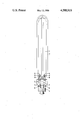
An embodiment of a lamp according to the invention is shown in the drawing in side elevation.
In the drawing, a discharge envelope or arc tube 2 provided with an ionizable-metal-vapor-containing gas filling is arranged in an evacuated outer bulb 2. Current-supply conductors 3 extend from a lamp cap 4 through the wall of the discharge envelope 1 to electrodes 5 arranged in the discharge envelope. The outer bulb 2 accommodates holders 6 from which a gettering metal layer 7 is deposited on the wall of the outer bulb.
Near each of the electrodes a respective open holder 8 is mounted in the discharge envelope and a gettering metal layer deposited on the wall of the discharge envelope 1 is situated opposite to this holder.
The lamp shown is a 35 W low-pressure sodium lamp with a gas filling of approximately 450 mg of Na and a mixture of 99% by volume of neon and 1% by volume of argon at a pressure of 1200 Pa. The electrodes have an emitter comprising a mixture of equimolar quantities of BaO, CaO, and SrO obtained from 22 mg of a corresponding mixture of carbonates. The open holders 6 and 8 are annular getters from which barium has evaporated. This getter material has deposited as layers 7 and 9, respectively, on the wall of the outer bulb 2 and of the discharge envelope 1, respectively. The holders contain a residue of mainly aluminum-nickel, and a small quantity of barium compound.
Claims (2)
1. A low-pressure alkali metal vapor discharge lamp, comprising an evacuated outer bulb; a discharge envelope arranged in said bulb; electrodes arranged in the discharge envelope for establishing an arc discharge path during operation of the lamp, said electrodes including an emitter comprising an alkaline earth metal oxide; current-supply conductors extending through a wall of said outer bulb and a wall of said discharge envelope to said electrodes; and a filling, contained in said envelope, comprising an inert gas and an ionizable alkali metal, in an operating condition of the lamp the arc discharge being carried primarily by alkali metal vapor,
characterized by comprising a getter holder and a getter for bi- and triatomic gases arranged in said envelope to achieve reduction in lamp starting voltage.
2. A lamp as claimed in claim 1, characterized in that said getter holder is an open holder having an opening, mounted near one of said electrodes, and in that a gettering metal layer is disposed in said envelope opposite said opening.
Applications Claiming Priority (2)
| Application Number | Priority Date | Filing Date | Title |
|---|---|---|---|
| NL8301447 | 1983-04-25 | ||
| NL8301447A NL8301447A (en) | 1983-04-25 | 1983-04-25 | LOW PRESSURE ALKALINE METAL VAPOR DISCHARGE LAMP. |
Publications (1)
| Publication Number | Publication Date |
|---|---|
| US4588919A true US4588919A (en) | 1986-05-13 |
Family
ID=19841753
Family Applications (1)
| Application Number | Title | Priority Date | Filing Date |
|---|---|---|---|
| US06/597,977 Expired - Fee Related US4588919A (en) | 1983-04-25 | 1984-04-09 | Low-pressure alkali metal vapor discharge lamp with arc tube gettering |
Country Status (7)
| Country | Link |
|---|---|
| US (1) | US4588919A (en) |
| JP (1) | JPS59205144A (en) |
| BE (1) | BE899492A (en) |
| DE (1) | DE3415225A1 (en) |
| FR (1) | FR2544915A1 (en) |
| GB (1) | GB2138996A (en) |
| NL (1) | NL8301447A (en) |
Cited By (3)
| Publication number | Priority date | Publication date | Assignee | Title |
|---|---|---|---|---|
| US4808877A (en) * | 1985-02-15 | 1989-02-28 | U.S. Philips Corporation | Low-pressure sodium discharge lamp having a collar-like heat shield |
| WO1999059188A1 (en) * | 1998-05-08 | 1999-11-18 | Koninklijke Philips Electronics N.V. | Low-pressure mercury vapor discharge lamp |
| WO2005073998A3 (en) * | 2004-01-05 | 2007-04-19 | Koninkl Philips Electronics Nv | Compact high-pressure discharge lamp and method of manufacturing |
Families Citing this family (1)
| Publication number | Priority date | Publication date | Assignee | Title |
|---|---|---|---|---|
| JPS6262448A (en) * | 1985-09-12 | 1987-03-19 | Nec Home Electronics Ltd | Optical recording and reproducing disc and optical recording and reproducing device |
Citations (4)
| Publication number | Priority date | Publication date | Assignee | Title |
|---|---|---|---|---|
| US4117369A (en) * | 1976-10-08 | 1978-09-26 | U.S. Philips Corporation | High-pressure discharge lamp |
| US4277717A (en) * | 1978-11-17 | 1981-07-07 | U.S. Philips Corporation | Low-pressure sodium vapor discharge lamp |
| US4380714A (en) * | 1980-01-15 | 1983-04-19 | U.S. Philips Corporation | High-pressure discharge lamp |
| US4461981A (en) * | 1981-12-26 | 1984-07-24 | Mitsubishi Denki Kabushiki Kaisha | Low pressure inert gas discharge device |
Family Cites Families (7)
| Publication number | Priority date | Publication date | Assignee | Title |
|---|---|---|---|---|
| GB679432A (en) * | 1949-12-01 | 1952-09-17 | Lumalampan Ab | Luminescent electric discharge lamp |
| GB913468A (en) * | 1960-03-10 | 1962-12-19 | Gen Electric Co Ltd | Improvements in or relating to sodium vapour electric discharge lamps |
| GB1419098A (en) * | 1972-08-11 | 1975-12-24 | Thron Electrical Ind Ltd | Gettering |
| NL7315641A (en) * | 1973-11-15 | 1975-05-20 | Philips Nv | HIGH PRESSURE GAS DISCHARGE LAMP. |
| US4032813A (en) * | 1974-08-19 | 1977-06-28 | Duro-Test Corporation | Fluorescent lamp with reduced wattage consumption having electrode shield with getter material |
| NL7712059A (en) * | 1977-11-02 | 1979-05-04 | Philips Nv | LOW PRESSURE SODIUM VAPOR DISCHARGE LAMP. |
| NL7907220A (en) * | 1979-09-28 | 1981-03-31 | Philips Nv | LOW PRESSURE METAL VAPOR DISCHARGE LAMP. |
-
1983
- 1983-04-25 NL NL8301447A patent/NL8301447A/en not_active Application Discontinuation
-
1984
- 1984-04-09 US US06/597,977 patent/US4588919A/en not_active Expired - Fee Related
- 1984-04-19 GB GB08410333A patent/GB2138996A/en not_active Withdrawn
- 1984-04-20 FR FR8406345A patent/FR2544915A1/en not_active Withdrawn
- 1984-04-21 DE DE19843415225 patent/DE3415225A1/en not_active Withdrawn
- 1984-04-21 JP JP59079370A patent/JPS59205144A/en active Pending
- 1984-04-24 BE BE0/212813A patent/BE899492A/en not_active IP Right Cessation
Patent Citations (4)
| Publication number | Priority date | Publication date | Assignee | Title |
|---|---|---|---|---|
| US4117369A (en) * | 1976-10-08 | 1978-09-26 | U.S. Philips Corporation | High-pressure discharge lamp |
| US4277717A (en) * | 1978-11-17 | 1981-07-07 | U.S. Philips Corporation | Low-pressure sodium vapor discharge lamp |
| US4380714A (en) * | 1980-01-15 | 1983-04-19 | U.S. Philips Corporation | High-pressure discharge lamp |
| US4461981A (en) * | 1981-12-26 | 1984-07-24 | Mitsubishi Denki Kabushiki Kaisha | Low pressure inert gas discharge device |
Cited By (4)
| Publication number | Priority date | Publication date | Assignee | Title |
|---|---|---|---|---|
| US4808877A (en) * | 1985-02-15 | 1989-02-28 | U.S. Philips Corporation | Low-pressure sodium discharge lamp having a collar-like heat shield |
| WO1999059188A1 (en) * | 1998-05-08 | 1999-11-18 | Koninklijke Philips Electronics N.V. | Low-pressure mercury vapor discharge lamp |
| US6274981B1 (en) | 1998-05-08 | 2001-08-14 | U.S. Philips Corporation | Low-pressure mercury vapor discharge lamp with electrode shield |
| WO2005073998A3 (en) * | 2004-01-05 | 2007-04-19 | Koninkl Philips Electronics Nv | Compact high-pressure discharge lamp and method of manufacturing |
Also Published As
| Publication number | Publication date |
|---|---|
| NL8301447A (en) | 1984-11-16 |
| FR2544915A1 (en) | 1984-10-26 |
| GB2138996A (en) | 1984-10-31 |
| DE3415225A1 (en) | 1984-10-25 |
| GB8410333D0 (en) | 1984-05-31 |
| BE899492A (en) | 1984-10-24 |
| JPS59205144A (en) | 1984-11-20 |
Similar Documents
| Publication | Publication Date | Title |
|---|---|---|
| US2883571A (en) | Electric incandescent lamp | |
| US3384798A (en) | High pressure saturation vapor sodium lamp containing mercury | |
| US3558963A (en) | High-intensity vapor arc-lamp | |
| US3582702A (en) | Thermionic electron-emissive electrode with a gas-binding material | |
| US4894584A (en) | Electric lamp provided with a getter including palladium | |
| US4025812A (en) | Alumina ceramic alkali metal lamp having metal getter structure | |
| US4588919A (en) | Low-pressure alkali metal vapor discharge lamp with arc tube gettering | |
| CA2099393C (en) | Metal halide lamp | |
| US4620129A (en) | Gettered high pressure sodium lamp | |
| JPS60207241A (en) | Low voltage mercury vapor discharge lamp | |
| US5614784A (en) | Discharge lamp, particularly cold-start fluorescent lamp, and method of its manufacture | |
| US4380714A (en) | High-pressure discharge lamp | |
| US2959702A (en) | Lamp and mount | |
| CA1150757A (en) | High-pressure sodium vapour discharge lamp | |
| CA1249015A (en) | High pressure sodium lamp having improved pressure stability | |
| JPH0721981A (en) | Metal halide lamp | |
| US4620128A (en) | Tungsten laden emission mix of improved stability | |
| US2042195A (en) | Electric discharge device | |
| US6157132A (en) | Discharge lamp emission material | |
| US3886391A (en) | Hafnium activated metal halide arc discharge lamp | |
| GB1389620A (en) | Discharge tube provided with an electrode comprising nickel and aluminium | |
| US3364375A (en) | Metal vapor lamp thorium coated electrode | |
| US4209726A (en) | Low-pressure sodium vapor discharge lamp | |
| US2030437A (en) | Electric discharge device | |
| NL7810088A (en) | HIGH PRESSURE SODIUM VAPOR DISCHARGE LAMP. |
Legal Events
| Date | Code | Title | Description |
|---|---|---|---|
| AS | Assignment |
Owner name: U.S. PHILIPS CORPORATION 100 EAST 42ND ST., NEW YO Free format text: ASSIGNMENT OF ASSIGNORS INTEREST.;ASSIGNORS:KROONTJE, WIGGERT;OOSTVOGELS, FRANCISCUS M. P.;REEL/FRAME:004310/0637;SIGNING DATES FROM 19840507 TO 19840828 |
|
| REMI | Maintenance fee reminder mailed | ||
| LAPS | Lapse for failure to pay maintenance fees | ||
| STCH | Information on status: patent discontinuation |
Free format text: PATENT EXPIRED DUE TO NONPAYMENT OF MAINTENANCE FEES UNDER 37 CFR 1.362 |
|
| FP | Lapsed due to failure to pay maintenance fee |
Effective date: 19900513 |