US458366A - Stem winding and setting watch - Google Patents
Stem winding and setting watch Download PDFInfo
- Publication number
- US458366A US458366A US458366DA US458366A US 458366 A US458366 A US 458366A US 458366D A US458366D A US 458366DA US 458366 A US458366 A US 458366A
- Authority
- US
- United States
- Prior art keywords
- wheel
- watch
- stem
- setting
- winding
- Prior art date
- Legal status (The legal status is an assumption and is not a legal conclusion. Google has not performed a legal analysis and makes no representation as to the accuracy of the status listed.)
- Expired - Lifetime
Links
- 238000004804 winding Methods 0.000 title description 28
- 230000005484 gravity Effects 0.000 description 29
- 230000009471 action Effects 0.000 description 18
- 238000010276 construction Methods 0.000 description 16
- 230000008859 change Effects 0.000 description 7
- 230000006872 improvement Effects 0.000 description 7
- 230000007246 mechanism Effects 0.000 description 7
- 230000000694 effects Effects 0.000 description 4
- 241000234435 Lilium Species 0.000 description 1
- 230000004075 alteration Effects 0.000 description 1
- 230000008901 benefit Effects 0.000 description 1
- 230000008878 coupling Effects 0.000 description 1
- 238000010168 coupling process Methods 0.000 description 1
- 238000005859 coupling reaction Methods 0.000 description 1
- CEJLBZWIKQJOAT-UHFFFAOYSA-N dichloroisocyanuric acid Chemical compound ClN1C(=O)NC(=O)N(Cl)C1=O CEJLBZWIKQJOAT-UHFFFAOYSA-N 0.000 description 1
- 238000006073 displacement reaction Methods 0.000 description 1
- 230000001788 irregular Effects 0.000 description 1
Images


Classifications
-
- G—PHYSICS
- G04—HOROLOGY
- G04B—MECHANICALLY-DRIVEN CLOCKS OR WATCHES; MECHANICAL PARTS OF CLOCKS OR WATCHES IN GENERAL; TIME PIECES USING THE POSITION OF THE SUN, MOON OR STARS
- G04B27/00—Mechanical devices for setting the time indicating means
- G04B27/02—Mechanical devices for setting the time indicating means by making use of the winding means
- G04B27/06—Mechanical devices for setting the time indicating means by making use of the winding means with rocking bar
Definitions
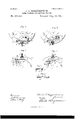
- FIG. 1 a broken View, partly in elevation and partly in section, of a watch-movement constructed in accordance with my invention and shown in its inverted position with its intermediate gravity part or coupler in the position which it will assume when the watch is inverted and before the stem has been manipulated.
- Fig. 2 is a similar view showing the coupling of the operating-lever with the operating-cam by the said gravity part consequent upon pushing in the stem when the parts are in the positions seen in Fig. 1.
- Fig. 3 is a similar View showing the rotated position of the operating-cam effected by the spring ot the operating-lever upon theremoval ot pressure from the stem when the parts are in the positions shown by Fig. 2.
- Fig. 2 is a similar view showing the coupling of the operating-lever with the operating-cam by the said gravity part consequent upon pushing in the stem when the parts are in the positions seen in Fig. 1.
- Fig. 3 is a similar View showing the rotated position of the operating-cam effected by the spring
- FIG. 4 is a similar view showing the watchmovement in its upright position with its gravity part disconnected from its operating lever, its operating-cam in its active position, and its stein drawn ont.
- Fig. 5 is a similar View showing the effect of pushingin the stem when the parts are in the positions shown by the preceding figure, the positions of the parts in this figure being their normal positions, except tor the operating-lever and the stem, the normal positions of which are indicated by broken lines.
- Fig. G is a broken view in elevation of the opposite side of the lower movement-plate with the yoke in position vfor setting the watch, the operating-eam being shown in its active position by broken lines.
- FIG. 7 is asimilar view showing the yoke in position for winding the watch, the operating-cam being shown in its retired or normal position by broken lines.
- Fig. S is a detached perspective view ot the gravity part or coupler.
- Fig. is a similar view ot' the operating-lever.
- Fig. 10 is a broken view, partly in elevation and partly in section, of a watch-movement, showing another form of my improvement and represented in its inverted position with its gravity partl in the position which it takes when the watch is inverted and before its stem has been pushed in.
- Fig. 11 is a similar View showing the rotation of the operating-cam and the adjustment of the watch for setting consequent upon pushing in the stein when the parts are in the positions shown by the piecetlinggtiie.
- Fig. 12 is a similar View showing the watch turned to its upright position and with its stem pulled out to permit the gravity part to change its position with respect to the operating-cam.
- Fig. 12 is a similar view showing the adjustment of the parts consequent upon pushing in the stem when they are adjusted, as shown in the preceding figure.
- Fig. 13 is a similar view showing the positions of the parts which are secured by pulling out the stem preparatory to setting the watch but without inverting the same.
- Fig. l-t is a broken view in elevation of the opposite side of the lower movement-plate, and showing the yoke in position t'or setting' the watch.
- Fig. 15 is a similar view with the yoke in position for winding the watch.
- Fig. 12 is a similar View showing the watch turned to its upright position and with its stem pulled out to permit the gravity part to change its position with respect to the operating-cam.
- Fig. 12 is a similar view showing the adjustment of the parts consequent upon pushing in the stem when they are
- FIG. 1G is a sectional view on the line :t a; of Fig. 12, Fig. 17 is a detached perspective View ot' the gravit-y part.
- Fig. 1S is a sectional view through the operating-lever and gravity part on the line x .t ot Fig. 11.
- Fig. 19 is a broken view, partly in elevation and partlyin section,of a watch, showing another form of my improvement, and represented with its parts in their normal adjustment, which I assume to be the adjustment ot parts obtaining the greater part of the time.
- Fig. 20 is a sectional view on the line 0c :r of Fig. 19, and showing the intermediate setting-wheel held in its retired adjustment by the gravity part.
- FIG. 21 is a vien' generally corresponding to Fig. 1f), but showing the watch inverted with its stem pulled out to permit the gravity part to act in releasing the intermediate setting-wheel.
- Fig. 22 is a sectional viewon the line y 'y of Fig. 21, and showing how the said wheel drops down into mesh with the minute-wheel consequentupon placing the watchin a horizontal position with its face upward after the parts have been brought into the adjustment IOO shown by the preceding figure.
- Fig. 23 is a view generally corresponding to Fig. 19, and showing the next position ot the watch after Fig. 22, the watch being placed in its upright position to cause its weight or gravity part to resume its normal position and thus retire the intermediate setting-wheel, as clearly shown also by Fig.
- Fig. 2i is adetached perspective view of the gravity part employed in this construction.
- Fig. 25 is a broken view, partly in elevation and partly in section, of another form which my improvement may assume, the parts being shown in their normal or winding positions by full lines and in their setting positions by broken lines.
- Fig. 26 is a viewJ partly in section and partly in elevation, showing the intermediate setting-wheel and the weight attached to its stalt locked in their normallyretired positions.
- FIG. 27 is a similar but ampliiied view showing the minute-wheels and the staff carrying the bowed lockingarms.
- Fig. 2S is a view showing the intermediate setting-wheel and weight locked in the operative position ot the former.
- Fig. 29 is a broken view in elevation of another form of my improvement herein employing a weight to swing the yoke from the winding to the setting' position of the same.
- Fig. 30 is a detached view in edge elevation of the weight shown by the preceding ligure.
- Fig. 3l is a broken view in elevation showing still another form of my improvement herein relying solely upon the weight ot the intermediate steeringwheel and its staff to shift it in position.
- Fig. 32 is a sectional view on the line :t of Fig. 3l, showing the watch in position for the Wheel to be moved by gravity into its active position.
- Fig. is a similar view showing the wheel in that position.
- My invention relates to an improvement in stem-winding and stem-setting watches, the object being to provide for setting the hands without opening the case and to avoid the displacement et the hands by the accidental shifting of either the winding or setting mechanism.
- my invention consists in an'intermediate part located between the stem and the settin g mechanism of a watch and constructed and arranged to respond to the action of gravity when the watch is placed in a predetermined position, and thus effect a change in the operative conditions within the watch with respect to the stem.
- My invention further consists in certain details of construction and combinations oil parts, as will be hereinafter described, and pointed out in the claims.
- an intermediate wheel made heavy enough to respond tothe action otl gravity when the watch is placed in certain positions or the weight may be placed upon the staff ot' the intermediate wheel, or the weight having ⁇ a cam-face may be pivotcd within the watch and arranged to act upon the sau of the intermediate wheel, or the weight may have the term of a latch constructed to co-opcrate with a cam which operates on the staff .of the intermediate wheel, or it may have the form of a'coupler co-operating with a cam acting upon the staff of the intermediate wheel, or the weight may have still other forms and operate in still other ways7 and yet embrace my invention, which consists, broadly,in a weight forming an intermediate part between the stem and the setting-train ot a watch and constructed and arranged to respond to the action of gravity when the watch is placed in a predetermined position, so as te change the operative conditions within the watch with respect to the said stem.
- Figs. l to 9, inclusive illustrate that vl'orm of my invention in which the weight consists of a coupler, which under certain conditions connects an operating-lever with a cam acting upon the arbor or sau o' the intermediate setting-wheel, the watch being shown in several different positions to clearly illustrate the positions ot the parts under different circumstauces.
- the weight consists of a coupler A, composed of a bar having oiic ol' its ends provided with two beveled faces AA, which converge to a point and offset, as at A2, upon its inner face, the inner wall ot the said ol'l'- set being concaved, as at A, for engagement with a coupling-pin B, mounted in the tree end of an operating-lever ll', hung at its opposite end upon a stud B2.
- the other end of the coupler is pivotcd so as to swing freely upon a pin A4, mounted in an operating-cani C, hung upon a pin (y, but under sullicicnt friction so that it will not turn of its own weight.
- the inner end of the cam which is of irregular shape, is provided with a rounded linger C2, which engages with the adjacent end D of the staff of the intermediate settingwheel D', tho said wheel being' mounted (see Figs. G and 7) in one end of a yoke E of ordinary construction in this class oi' watches.
- An elongated slot D2, formed in the lower plate F ot the watch, is provided to permit the wheel D to be moved toward and away from the minute-wheel G, into which it meshes 'for setting the hands ol' the watch.
- wheel D is constantly in mesh with the main winding-wheel H, as is also the intermediate winding-wheel I, which is mounted in the op posite end of the yoke E from the intermediate setting-wheel D the wheel I being normally engaged, as will be hereinafter described, with the ratchet-wheel I of the winding-train.
- Fig. 3 of the drawings I have shown the watch turned upside down; but this is unnecessary, as the watch may be held in any position whatever just as soon as the operating-lever has been coupled with the cam by means of the coupler, which is not brought into position for operation except when the watch is turned with its stem directly downward.
- the operating-lever B will engage with the curved face presented to it by the cam C, whereby the said cam will be caused to rotate on its pin Cand whereby its finger C2 is disengaged from the adjacent end of the staff or arbor D of the intermediate setting-wheel D', permitting the yoke-spring L to act in swinging the yoke into its normal position, in which the said staff D is carried into the outer end of the slot D'rl and the wheel D disengaged from the minute-wheel G and the wheel I re-engaged with the wheel I, as shown by Figs. l, 2, and 7 of the drawings.
- the coupler A at this time responds again to the action of gravity and drops inward, but wit-hout any operative effect.
- Figs. l0 to IS of the drawings show an embodiment of my invention in which the weight has the form of a latch M, hung so as to swing freely on a pin M', carried by the free end of ITO IIS
- the longitudinally-bowed operating-lever N pivoted at its opposite end by a pin N to the lower plate F of the movement, the said lever being provided with a stem or finger N2, entering the main winding-pinion .I in position to be engaged by the longitudinally movable and rotatable stem K, the said pinion and stem being of ordinary construction.
- the latch H is provided upon its inner edge with an offsetting portion comprising a finger M2 and a banking-face M2, the inner edge of the latch being also shaped, as at M4, to tit the outer edge ot' the operating-cam O, which is hung upon a pivot O', located in the said plate F, and the inner edge of the said cam being cut away to receive the adjacent end D of the staff of the intermediate settingwheel D', which is engaged when the watch is adjusted for winding with the minutewheel G.
- the said staff D plays in a slot D2, formed in the plate F, and is carried by one end of the yoke E, as shown by Figs. 14 and 15 of the drawings.
- the opposite endof the said yoke carries the arbor I2 oi' the intermediate winding-wheel I, which is engaged when the watch is adjusted for Winding with the ratchet-wheel I', an elongated slot D3 being formed in the plate F for the arbor I2 to play in.
- a spring L2 engaging with the inner edge of the operating-lever, exerts a constant eitort to throw the same to the position in which it is shown by Figs. 10, 12, and 13 of the drawings, while a spring L3 (see Fig. 14) engages with the yoke and exerts a constant effort to engage the intermediate windingwheel I with the ratchet-wheel I.
- the winding and setting trains and the yoke of this watch are of ordinary construetion.
- the latch which moves inward with it will operate through its tinger M2 to turn the cam O on its axis 0 and thus force the intermediate setting-wheel D into engagement with theminnte-wheel G, the yoke E being swung on its center at the same time, so as to disengage its intermediate winding-wheel I from the ratchet-wheel I.
- the watch may now be set either in this position or in any other.
- This watch can only be adjusted for setting after it has been inverted and its stem drawn out and then 'forced in again, and after having been adjusted for setting it can only be readjusted for winding by placing it in an upright position and first drawing out the stem and then pushing the same in again.
- this watch also the chance of displacing the hands by accidentally shifting the setting mechanism is made so remote as to be practically disposed of altogether.
- the function of the weight I is to hold the intermediate setting-wheel D normally out of engagement with the minutewheel G, the weight being pivotally hung on the center Il of the main winding-wheel Il and provided with an inclined and slightlycurved groove I, which is 'formed in its inner face in position to receive the staff D of the wheel D.
- This watch is provided with an operatinglever R, hung at one end upon a pin R and provided at its other end with a pin R2, which is engaged by one end of a spring S, which also engages under certain conditions, as will be hereinafter described, with the arbor I2 of the intermediate setting-wheel I.
- a spring T located on the opposite side oi the movement-plate F, is arranged to hold the said wheel I in its normal position of engagement with the ratchet-wheel I.
- the said operating-lever R is provided with a linger R2, entering the central opening of the main winding-pinion J in position to be engaged Yby the Stem K, which, with the said intermediate winding-wheel and the main wheel ll, are of ordinary construction.
- the intermediate setting-wheel D is provided with a longstaft I), arranged to have longitudinal movement in the two plates of the watch-movement, and
- the weight X is hung near one of its ends upon a stud X an d constructed with an inclined slot X2, which receives one end of the staff I2 of the intermediate windin ⁇ g-wheel I, the said sau also passing through a short slot I2, formed in the lower movementplate and located in a circle concentric with the center of the yoke.
- the combination in a stem winding and stein setting watch, the combination, with a rotatable stem, of winding and setting mechanism and an in termediate part locatedbetween the said stem and the setting ⁇ mechanism, the said part being constructed and arranged to respond to the action of gravity when the watch is placed in a predetermined position and thus effect a change in the operative conditions within the watch with respect to the stem, substantially as described.
- a stem -winding and stem -setting watch the combination, with a rotatable stem, of awinding and a setting train and intermediate parts located between the stem and setting-train, and including a wheel movable toward and away from the'train ⁇ a cam to move the pinion in one direction, means for moving it in the opposite direction, and a weight constructed and arranged to respond to the action of gravity when the watch is placed in a predetermined position and to co-operate with the said cam in changing the ceases operative conditions within the watch lwith respect tothe stem, substantially as described.
- a stem -winding and stem setting Watch the combination, with a rotatable and longitudinally-movablc stem, of a winding tra-in and a setting-train, an intermediate setting-wheel movable toward and away from the setting-train, a cam engaging with the staff of said wheel, an operating-lever adapted to be moved in one direction by the stein, a spring for moving the said-lever in the opposite direction, and a pivoted weight constructed and arranged to respond to the action of gravity when the watch is placed in a predetermined position, and virtually forming a connection between the operating-lever and the said cam, substantially as set forth.
- a stem -winding and stem-setting watch the combination, with a rotatable and longitudinally-movable stem, of a windingtrain and a setting-train, an intermdiate setting-wheel adapted to be moved toward and away from the setting-train, a cam to engage with the staif of the said wheel, an operatinglever adapted to be moved in one direction by the stem, a spring for moving the said lever in the opposite direction, and a coupler pivotallyattached tothe said cam and adapted to engage with a pin carried by the said lever when the watch is placed in a predetermined position, substantially as set forth, and whereby the said cam and lever are coupled together.
- a stem-winding and stem setting watch the combination, with a rotatable and longitudinally-inovable stem, of a windingtrain and a setting-train, a yoke carrying an intermediate setting-wheel at one end andan intermediate winding-wheel at the other end, a cam engaging with the staff ol' the said setting-wheel, an operating-lever adapted to be moved in one direction by the said stem, a spring for moving the lever in the opposite direction, a spring for normally holding the yoke, with its winding-wheel, in engagement with the winding-train, and a coupler pivotally attached to the cam and adapted to be engaged with a pin located in the operatinglever when the watch has been placed in an inverted position with its stem directly downward, substantially as described.
- a coupler having one of its ends provided with two converging beveled faces and with an offset the inner edge of which is concaved, substantially as described.
Landscapes
- Physics & Mathematics (AREA)
- General Physics & Mathematics (AREA)
- Electromechanical Clocks (AREA)
Description
`(Nu Model.) 5 Sheets-Sheet L C. T. HIGGI'NBOTHAM. STEM WINDING AND SETTING WATCH.
N0.- 458,366. Patentad Aug. 25, 1891.
5 Sheets-Sheet 2.
(No Model.)
C. T. HIGGINBOTHAM.
STEM WINDING AND SETTING WATCH.
No. 458,366. Patented Aug. 25,1891.
(No Model.) 5 Sheets-Sheet 3.
C. T. HIGGINBOTHAM. STEM WINDING AND SETTING WATCH.
No. 458,366. Patented Aug. 25, 1891.
w: News Farms co.. morcyuma.. wasmnuron. n. c.
(No Model.) 5 Sheets-Sheet 4. C. T. HIGGINBOTHAM. STEM WINDING AND SETTING WATCH.
No. 458,366. Patented Aug. 25, 1891.
(No Model.) heets--Sheetv 5.
C. T. HIGGINBGTHAM. STEM WINDING AND SETTING WATCH.
No. 458,366. PatentedfAug. 25,1891.
l wrlmmn UNITED STATES PATENT OEEIcE.
CHARLES T. HIGGINBOTIIAM, OF THOMAS'ION, CONNECTICUT.
STEM WINDING AND SETTING WATCH.
SPECIFICATION 'forming part of Letters Patent No. 458,366, dated August 25, 1891.
Avplication tiletlApril l0, 1891. Serial No. 388,395. (No model.)
To @ZZ whom it may concern:
Beit known that I, CHARLES T. HIGGIN- IBOTHAM, of Thomaston, in the county of Litchfield and State of Connecticut, have invented new Improvements in Stem-finding and Stem-Setting ratchesg and I do hereby declare the following, when taken in connection with accompanying drawings and the letters of reference marked thereon, to be a full, clear, and exact description of the same, and which said drawings constitute part ot' this specilication, and represent, in-
Figure 1, a broken View, partly in elevation and partly in section, of a watch-movement constructed in accordance with my invention and shown in its inverted position with its intermediate gravity part or coupler in the position which it will assume when the watch is inverted and before the stem has been manipulated. Fig. 2 is a similar view showing the coupling of the operating-lever with the operating-cam by the said gravity part consequent upon pushing in the stem when the parts are in the positions seen in Fig. 1. Fig. 3 is a similar View showing the rotated position of the operating-cam effected by the spring ot the operating-lever upon theremoval ot pressure from the stem when the parts are in the positions shown by Fig. 2. Fig. 4 is a similar view showing the watchmovement in its upright position with its gravity part disconnected from its operating lever, its operating-cam in its active position, and its stein drawn ont. Fig. 5 is a similar View showing the effect of pushingin the stem when the parts are in the positions shown by the preceding figure, the positions of the parts in this figure being their normal positions, except tor the operating-lever and the stem, the normal positions of which are indicated by broken lines. Fig. G is a broken view in elevation of the opposite side of the lower movement-plate with the yoke in position vfor setting the watch, the operating-eam being shown in its active position by broken lines. Fig. 7 is asimilar view showing the yoke in position for winding the watch, the operating-cam being shown in its retired or normal position by broken lines. Fig. S is a detached perspective view ot the gravity part or coupler. Fig. is a similar view ot' the operating-lever. Fig. 10 is a broken view, partly in elevation and partly in section, of a watch-movement, showing another form of my improvement and represented in its inverted position with its gravity partl in the position which it takes when the watch is inverted and before its stem has been pushed in. Fig. 11 is a similar View showing the rotation of the operating-cam and the adjustment of the watch for setting consequent upon pushing in the stein when the parts are in the positions shown by the piecetlinggtiie. Fig. 12 is a similar View showing the watch turned to its upright position and with its stem pulled out to permit the gravity part to change its position with respect to the operating-cam. Fig. 12 is a similar view showing the adjustment of the parts consequent upon pushing in the stem when they are adjusted, as shown in the preceding figure. Fig. 13 is a similar view showing the positions of the parts which are secured by pulling out the stem preparatory to setting the watch but without inverting the same. Fig. l-t is a broken view in elevation of the opposite side of the lower movement-plate, and showing the yoke in position t'or setting' the watch. Fig. 15 is a similar view with the yoke in position for winding the watch. Fig. 1G isa sectional view on the line :t a; of Fig. 12, Fig. 17 is a detached perspective View ot' the gravit-y part. Fig. 1S is a sectional view through the operating-lever and gravity part on the line x .t ot Fig. 11. Fig. 19 is a broken view, partly in elevation and partlyin section,of a watch, showing another form of my improvement, and represented with its parts in their normal adjustment, which I assume to be the adjustment ot parts obtaining the greater part of the time. Fig. 20 is a sectional view on the line 0c :r of Fig. 19, and showing the intermediate setting-wheel held in its retired adjustment by the gravity part. Fig. 21 is a vien' generally corresponding to Fig. 1f), but showing the watch inverted with its stem pulled out to permit the gravity part to act in releasing the intermediate setting-wheel. Fig. 22 is a sectional viewon the line y 'y of Fig. 21, and showing how the said wheel drops down into mesh with the minute-wheel consequentupon placing the watchin a horizontal position with its face upward after the parts have been brought into the adjustment IOO shown by the preceding figure. Fig. 23 is a view generally corresponding to Fig. 19, and showing the next position ot the watch after Fig. 22, the watch being placed in its upright position to cause its weight or gravity part to resume its normal position and thus retire the intermediate setting-wheel, as clearly shown also by Fig. 20, and the normal adjustment of parts, as shown by Fig. 1),being secured by pushing in the stem to permit theintermediate winding-wheel to re-engage with the ratchetwheel of the winding-train and the operatinglever to lock the gravity part in place. Fig. 2i is adetached perspective view of the gravity part employed in this construction. Fig. 25 is a broken view, partly in elevation and partly in section, of another form which my improvement may assume, the parts being shown in their normal or winding positions by full lines and in their setting positions by broken lines. Fig. 26 is a viewJ partly in section and partly in elevation, showing the intermediate setting-wheel and the weight attached to its stalt locked in their normallyretired positions. Fig. 27 is a similar but ampliiied view showing the minute-wheels and the staff carrying the bowed lockingarms. Fig. 2S is a view showing the intermediate setting-wheel and weight locked in the operative position ot the former. Fig. 29 is a broken view in elevation of another form of my improvement herein employing a weight to swing the yoke from the winding to the setting' position of the same. Fig. 30 is a detached view in edge elevation of the weight shown by the preceding ligure. Fig. 3l is a broken view in elevation showing still another form of my improvement herein relying solely upon the weight ot the intermediate steeringwheel and its staff to shift it in position. Fig. 32 is a sectional view on the line :t of Fig. 3l, showing the watch in position for the Wheel to be moved by gravity into its active position. Fig. is a similar view showing the wheel in that position.
My invention relates to an improvement in stem-winding and stem-setting watches, the object being to provide for setting the hands without opening the case and to avoid the displacement et the hands by the accidental shifting of either the winding or setting mechanism.
NVith these ends in view my invention consists in an'intermediate part located between the stem and the settin g mechanism of a watch and constructed and arranged to respond to the action of gravity when the watch is placed in a predetermined position, and thus effect a change in the operative conditions within the watch with respect to the stem.
My invention further consists in certain details of construction and combinations oil parts, as will be hereinafter described, and pointed out in the claims.
ln carrying out my invention the intermediate part constructed and arranged to respond to the action ot gravity, as described,
may take a variety et different forms and act in quite different ways. It may, for instance, consist of an intermediate wheel made heavy enough to respond tothe action otl gravity when the watch is placed in certain positions or the weight may be placed upon the staff ot' the intermediate wheel, or the weight having` a cam-face may be pivotcd within the watch and arranged to act upon the statt of the intermediate wheel, or the weight may have the term of a latch constructed to co-opcrate with a cam which operates on the staff .of the intermediate wheel, or it may have the form of a'coupler co-operating with a cam acting upon the staff of the intermediate wheel, or the weight may have still other forms and operate in still other ways7 and yet embrace my invention, which consists, broadly,in a weight forming an intermediate part between the stem and the setting-train ot a watch and constructed and arranged to respond to the action of gravity when the watch is placed in a predetermined position, so as te change the operative conditions within the watch with respect to the said stem.
I have shown in the accompanying drawings several diterent ways ot' carrying out my invention, the same being some of the ditferent specific forms above mentioned.
Figs. l to 9, inclusive, illustrate that vl'orm of my invention in which the weight consists of a coupler, which under certain conditions connects an operating-lever with a cam acting upon the arbor or statt o' the intermediate setting-wheel, the watch being shown in several different positions to clearly illustrate the positions ot the parts under different circumstauces.
The winding and setting trains of the watch are of ordinary construction and are therefore not fnlly shown, but only sufficiently to illustrate the application of my invention. In this case the weight consists of a coupler A, composed of a bar having oiic ol' its ends provided with two beveled faces AA, which converge to a point and offset, as at A2, upon its inner face, the inner wall ot the said ol'l'- set being concaved, as at A, for engagement with a coupling-pin B, mounted in the tree end of an operating-lever ll', hung at its opposite end upon a stud B2. The other end of the coupler is pivotcd so as to swing freely upon a pin A4, mounted in an operating-cani C, hung upon a pin (y, but under sullicicnt friction so that it will not turn of its own weight. The inner end of the cam, which is of irregular shape, is provided with a rounded linger C2, which engages with the adjacent end D of the staff of the intermediate settingwheel D', tho said wheel being' mounted (see Figs. G and 7) in one end of a yoke E of ordinary construction in this class oi' watches.
An elongated slot D2, formed in the lower plate F ot the watch, is provided to permit the wheel D to be moved toward and away from the minute-wheel G, into which it meshes 'for setting the hands ol' the watch. The said IOO IOS
TIO
wheel D is constantly in mesh with the main winding-wheel H, as is also the intermediate winding-wheel I, which is mounted in the op posite end of the yoke E from the intermediate setting-wheel D the wheel I being normally engaged, as will be hereinafter described, with the ratchet-wheel I of the winding-train.
The operating-lever B, before mentioned, is provided about midway of its length, and upon its outer face, with a finger B3, which enters the hollow winding-pinion J, which is geared into the main winding-wheel II, in position to be engaged by the longitudinallymovable and rotatable stem or arbor K. A spring L, arranged to engage with the inner edge of the said operating-lever, normally holds it in its outward position, in which it is shown by Figs. l and 4t of the drawings. A lighter spring L engages with that end of the yoke E carrying the intermediate windingwheel I, and exerts a constant effort to throw the said wheel into engagement with the ratchet-wheel I.
The normal condition of parts in the watch just above described will obtain when the wheel I is engaged with the ratchet-wheel I and the wheel D is disengaged from the minute-wheel G. In order to reverse these connections and place the watch in adjustment for setting, it must be held in an inverted position, with its stem directly downward, as shown by Figs. I, 2, and 3 of the drawings. By placing the watchin this position the coupler A, which swings freely on its pivot A4, will respond to the action of gravity and assume the position in which it is shown by Fig. l of the drawings. The stem J of the watch is now pushed inward, carrying the operating-lever B with it, and causing the coupling-pin B thereof to be engaged with one of the bevelfaces A upon the adjacent end of the coupler, whereby the same is pushed one side to permit the pin to pass the offset A2 of the coupler, which will then swing into position for receiving the said pin in its concaved face A3, as shown by Fig. 2 of the drawings. rlhe cam C and the operating-lever B having now been coupled together by the coupler A, pressure upon the stem K is removed, and the spring L, which has been placed under tension by the inward movement of the stem, will operate to restore the operating-lever to its normal position, and in so doing rotate the cam C on its pin C', whereby the staff D of' the intermediate setting-wheel D will be caused to ride up the inclined inner face of the finger C2 of the said cam and forced into the inner end of the slot D2, in which position it is locked bythe said finger of the cam, as shown by Figs. 3 andec of the drawings. This movement of the arbor D and the wheel D brings the latter into mesh with the minutewheel G, and thusplaces the watch in adjustment for setting, the described movement of the wheel D having turned the yoke E on its center against the tension of the spring L', and caused a corresponding movement of the intermediate winding-wheel I away from t-he ratchet-wheel I.
In Fig. 3 of the drawings I have shown the watch turned upside down; but this is unnecessary, as the watch may be held in any position whatever just as soon as the operating-lever has been coupled with the cam by means of the coupler, which is not brought into position for operation except when the watch is turned with its stem directly downward.
I would call attention to the factl that preparatory to placing the watch in adjustment for setting it is absolutely necessary that it be held in an inverted position in order to cause the coupler to be swung by gravityinto position to engage with the coupling-pin B, carried by the operating-lever. Just as soon, however, as that has been effected, the watch may be heldin any lposition while it is being set. On the other hand, the watch may be adjusted for winding when heldin any position. For convenience of illustration, however, I have chosen to illustrate the readjustment of the watch with the samein its ordinary position or with the stem upward,as shown byFigs. 4t and of the drawings. It will be observed that, as shown by Fig. et of the drawings, the watch is in its setting adjustment. If now the stem be pushed inward, the operating-lever B will engage with the curved face presented to it by the cam C, whereby the said cam will be caused to rotate on its pin Cand whereby its finger C2 is disengaged from the adjacent end of the staff or arbor D of the intermediate setting-wheel D', permitting the yoke-spring L to act in swinging the yoke into its normal position, in which the said staff D is carried into the outer end of the slot D'rl and the wheel D disengaged from the minute-wheel G and the wheel I re-engaged with the wheel I, as shown by Figs. l, 2, and 7 of the drawings. The coupler A at this time responds again to the action of gravity and drops inward, but wit-hout any operative effect.
It will be apparent from the foregoing deseription that a watch provided with my invention when constructed as shown by Figs. l to 9 of the drawings can onlybe put in adjustment for setting by first inverting it in position and then pushing its stem inward and withdrawing it, but that the watch can be set for winding inany of its positions. The danger of displacing the hands by the accidental shifting of the setting mechanism is therefore in this watch reduced to almost nothing, for it is impossible to conceive that the watch could be accidentally brought into an inverted position and have its stem thrust inward and then withdrawn, and in no other way can the setting-train be brought into position for operation.
Figs. l0 to IS of the drawings show an embodiment of my invention in which the weight has the form of a latch M, hung so as to swing freely on a pin M', carried by the free end of ITO IIS
IZO
the longitudinally-bowed operating-lever N, pivoted at its opposite end by a pin N to the lower plate F of the movement, the said lever being provided with a stem or finger N2, entering the main winding-pinion .I in position to be engaged by the longitudinally movable and rotatable stem K, the said pinion and stem being of ordinary construction. The latch H is provided upon its inner edge with an offsetting portion comprising a finger M2 and a banking-face M2, the inner edge of the latch being also shaped, as at M4, to tit the outer edge ot' the operating-cam O, which is hung upon a pivot O', located in the said plate F, and the inner edge of the said cam being cut away to receive the adjacent end D of the staff of the intermediate settingwheel D', which is engaged when the watch is adjusted for winding with the minutewheel G. The said staff D plays in a slot D2, formed in the plate F, and is carried by one end of the yoke E, as shown by Figs. 14 and 15 of the drawings. The opposite endof the said yoke carries the arbor I2 oi' the intermediate winding-wheel I, which is engaged when the watch is adjusted for Winding with the ratchet-wheel I', an elongated slot D3 being formed in the plate F for the arbor I2 to play in. A spring L2, engaging with the inner edge of the operating-lever, exerts a constant eitort to throw the same to the position in which it is shown by Figs. 10, 12, and 13 of the drawings, while a spring L3 (see Fig. 14) engages with the yoke and exerts a constant effort to engage the intermediate windingwheel I with the ratchet-wheel I.
The winding and setting trains and the yoke of this watch are of ordinary construetion.
When it is desired to place a watch constructed as shown in Figs. 10 to 1S' of the drawings in adjustment for setting the hands, it is inverted, as shown by Fig. 10 of the drawings, and its stem pulled outward. If preferred, this may be done before inverting the watch, as shown by Fig. 13, whereby its latch is permitted to assume under the action of gravity the position in which it is shown in the said figure, the engagement of its banking-face M3 with the inner edge of the operatinglever M preventing it from falling too far. The iinger M2 of the latch is thus brought into range with the outer edge of the cam at a point thereon inside of the pivot O', so that when the stem is pushed inward, as shown by Fig. 11 of lthe drawings, the latch which moves inward with it will operate through its tinger M2 to turn the cam O on its axis 0 and thus force the intermediate setting-wheel D into engagement with theminnte-wheel G, the yoke E being swung on its center at the same time, so as to disengage its intermediate winding-wheel I from the ratchet-wheel I. The watch may now be set either in this position or in any other.
To readjust the watch for winding, it is placed in its ordinary position with its stem upward and the stem pulled out, permitting the spring L2 to lift the operating-lever N and also the latch M, which is permitted to drop, so that its finger M2 will be carried on the outside of the pin O of the cam O and adjacent to the outer edge of the cam, as shown by dotted lines, Fig. 12. IVhen now the stem is thrust in again, the said finger M2 engages with the outer edge of the cam and turns the same on its pivot O', (see Fig. 19%) whereby it releases the statt D of the intermediate setting-wheel D', so that the spring L3 may at once operate to swing the yoke E, and thus engage the wheel I with the ratchet-wheel I. This watch, it will be seen, can only be adjusted for setting after it has been inverted and its stem drawn out and then 'forced in again, and after having been adjusted for setting it can only be readjusted for winding by placing it in an upright position and first drawing out the stem and then pushing the same in again. In this watch also the chance of displacing the hands by accidentally shifting the setting mechanism is made so remote as to be practically disposed of altogether.
In the construction shown by Figs. 15J to 24- of the drawings the function of the weight I is to hold the intermediate setting-wheel D normally out of engagement with the minutewheel G, the weight being pivotally hung on the center Il of the main winding-wheel Il and provided with an inclined and slightlycurved groove I, which is 'formed in its inner face in position to receive the staff D of the wheel D.
This watch is provided with an operatinglever R, hung at one end upon a pin R and provided at its other end with a pin R2, which is engaged by one end of a spring S, which also engages under certain conditions, as will be hereinafter described, with the arbor I2 of the intermediate setting-wheel I. A spring T, located on the opposite side oi the movement-plate F, is arranged to hold the said wheel I in its normal position of engagement with the ratchet-wheel I. The said operating-lever R is provided with a linger R2, entering the central opening of the main winding-pinion J in position to be engaged Yby the Stem K, which, with the said intermediate winding-wheel and the main wheel ll, are of ordinary construction.
In any of the ordinary positions which a watch constructed as shown in Figs. 19 to 24 would assume the weight l? will maintain the position in which it is shown by Figs. 1l), 20, and 23 of the drawings and keep the intermediate setting-wheel in its retired or cutout position. To set the watch, it is inverted and its stem pulled out, as shown byv Fig. 21 of the drawings, whereupon the weight l? will respond to the action of gravity and drop away from the arbor D, so as to bring the outer and deeper part of its groove P in alignment with the same. At the same time the pulling out oi the stem permits the spring S to engage with the arbor I2 ol the interme TCO ITO
IIS
diate Windingwheel I and move the said wheel outward through the length of the slot I3 in the plate F and against the tension of the spring T, which is thc weaker of the two, the wheel I thus being disengaged `lrom the ratchet-wheel I. If now the watch is placed in a horizontal position with its face upward, the pinion D will drop by gravity into engagement Withthe minute-wheel G, as shown by Fig. 22 of the drawings, after which the watch may be set.
To restore the watch into adjustment for winding, it has only to be placed with its stem or pendant upward, for then the weight P will at once respond to the action of gravity, and by engaging the inclined bottom of its groove P with the end of the stati D force the setting-wheel D out of engagement with the minute-wheel G and into its retired position, as shown by Fig. 20. The stem is now pushed inward again, as shown by Fig. 19, whereby the spring S is disengaged from the arbor I2, leaving the spring T t'ree to re-engage the winding-wheel I with the ratchetwheel I. In this construction two olf the intermediate parts between the stem and the setting-train-namely, the weight P and the intermediate setting-wheel D-are constructed to respond to the action oi gravit-y, one when the watch is in one position and the other when the watch is in another position. The construction last considered is simple and reliable; but perhaps the chances of its accidental operation are not quite as remote as some ot' the constructions heretofore considered.
In the construction shown by Figs. 25 to 28, inclusive, of the drawings the intermediate setting-wheel D is provided with a longstaft I), arranged to have longitudinal movement in the two plates of the watch-movement, and
provided with a cylindrical weight U', having its upper end furnished with an annular groove Uand its lowerend provided with abevel U2. The said wheel D is locked in its respective positions by means of two longitudinallybowed locking-arms V and V wedge-shaped in cross section and secured at dil-'ferent points on the length of a staii V2, which also carries an operating-lever V3, provided with a finger V4, which enters the main windingpinion J in position for engagement with the stem K. rlhe outer end of the said lever V3 is engaged by the spring IV, which moves the said lever outward when the stem K is withdrawn and engages with the arbor I2 of the intermediate winding-wheel I and moves the said wheel in the slot I3 and disengages it from the ratchet-wheel, which is not shown in these figures of the drawings. A lighter spring IV is provided for holding the intermediate winding-wheel in normal engagement with the ratchet-wheel when the stem K is pressed inward, as shown by Fig. 25 of the drawings. Normally the bowed arm V engages with the bevel U2, formed at the lower end of the weightdl, as shown by full lines in Fig. 2li of the drawings,and holds the said weight and the wheel D in their retired positions.
\Vhen it is desired to adjust the watch for Setting, it is placed in a horizont-ul position with its l'ace downward and the stem pulled outward. This will release the weight U, which will fall and carry the wheel D with it and inte engagement with the minute-wheel G, as shown by broken lines in Fig. 27 of the drawings. 'lhis will take place while the arm V is moving toward the weight and the arm V moving away from the same and before they reach the positions in which they are shown by full lilies in Fig. 2S of the drawings, the arm V in that ligure co-operating with the weight to hold the wheel D in engagementwiththe minute-wheel G. At the same time the spring' XV will litt the outer end of the arm V3 into engagement with the arbor I2 of the intermediate winding-wheel I and disconnects the same from the ratchet-wheel.
vTo readjust the watchior winding, its stem is thrust in, whereby the arm V will be cleared from the upper end ot` the weight and the arm V engaged with the bevel U2, formed at the lower end thereof, the weight being i'orced into its retired position by the beveled edge ot the arm V, as shown by full lines in Fig. 26 of lthe drawings. The purpose of the annular groove formedin the upper end of the weight U is yet to be explained. It provides for locking the weight in its retired position in case thestem should be withdrawn while the watch is in any other position than horizontal, with its face down, for whenever the stem is pulled out without a simultaneous movement of the weight by the action of gravit)v the arm V is cut into the said groove.
In the construct-ion shown by Figs. 20 and 30 ofthe drawings the weight X is hung near one of its ends upon a stud X an d constructed with an inclined slot X2, which receives one end of the staff I2 of the intermediate windin `g-wheel I, the said statt also passing through a short slot I2, formed in the lower movementplate and located in a circle concentric with the center of the yoke. When a watch thus constructed is inverted, the weight in responding to the action et gravity and :Falling will overcome the tension of the spring employed for holding the yoke normally in position for the engagementof the intermediate winding-wheel I, carried by it,with the ratchetwheel and temporarily swing the yoke to reverse its position and engage its intermediate setting-wheel D with the minute-wheel G, the inclined walls of the slot X2 operating upon the stud l2 to swing the yoke.
In the construction shown by Figs. 3l, 32, and 33 of the drawings the weight of the wheel D is alone relied upon to move it into its operative position when the watch has been properly placed for such action. This construct-ion does not require a longitudinallymovable stem, to which, therefore, myinvention is not limited. The shifting ot` the wheel IOO IIO
ISO
does, however, change the operative conditions Within the watch with respect to the stem thereof. It will thus be seen that by means of a weighted part, whether the same be the intermediate setting-wheeler a weight acting directly upon the same, or a weight acting upon a cam directly engaging with the staff of the said wheel, or a weight nsed as a coupler, I am enabled, by taking advantage of the action of gravity, to change the operative conditions within the watch with respect to the stem thereof by simply placing the watch in one or more predetermined positions, and that by selecting the positions and properly adapting my mechanism thereto I am enabled to reduce the chance of the accidental shifting` of the hands to the minimum. At the same time my device is of comparatively simple construction and reliable operation, and is applicable to stem-winding and stemsetting watches as now constructed. I would therefore have it understood that I do not limit myself to the exact construction herein shown and described, but hold myself at liberty to make such changes and alterations as fairly fall within the spirit and scope of my invention.
Having fully described my invention, what I claim as new, and desire to secure by Iletters Patent, is-
l. In a stem winding and stein setting watch, the combination, with a rotatable stem, of winding and setting mechanism and an in termediate part locatedbetween the said stem and the setting` mechanism, the said part being constructed and arranged to respond to the action of gravity when the watch is placed in a predetermined position and thus effect a change in the operative conditions within the watch with respect to the stem, substantially as described.
2. In a stem-winding and. stem setting watch, the combination, with a rotatable stem, of winding and setting trains and intermediate parts, including a wheel movable toward and away from the setting-train and a weight constructed and arranged to respond to the action of gravity when the watch is placed in a predetermined position and thus change the operative conditions within the watch with respect to the stem, substantially as described.
In a stem -winding and stem -setting watch, the combination, with a rotatable stem, of awinding and a setting train and intermediate parts located between the stem and setting-train, and including a wheel movable toward and away from the'train` a cam to move the pinion in one direction, means for moving it in the opposite direction, and a weight constructed and arranged to respond to the action of gravity when the watch is placed in a predetermined position and to co-operate with the said cam in changing the ceases operative conditions within the watch lwith respect tothe stem, substantially as described.
Li. In a stem -winding and stem setting Watch, the combination, with a rotatable and longitudinally-movablc stem, of a winding tra-in and a setting-train, an intermediate setting-wheel movable toward and away from the setting-train, a cam engaging with the staff of said wheel, an operating-lever adapted to be moved in one direction by the stein, a spring for moving the said-lever in the opposite direction, and a pivoted weight constructed and arranged to respond to the action of gravity when the watch is placed in a predetermined position, and virtually forming a connection between the operating-lever and the said cam, substantially as set forth.
5. In a stem -winding and stem-setting watch, the combination, with a rotatable and longitudinally-movable stem, of a windingtrain and a setting-train, an intermdiate setting-wheel adapted to be moved toward and away from the setting-train, a cam to engage with the staif of the said wheel, an operatinglever adapted to be moved in one direction by the stem, a spring for moving the said lever in the opposite direction, and a coupler pivotallyattached tothe said cam and adapted to engage with a pin carried by the said lever when the watch is placed in a predetermined position, substantially as set forth, and whereby the said cam and lever are coupled together.
(3. In a stem-winding and stem setting watch, the combination, with a rotatable and longitudinally-inovable stem, of a windingtrain and a setting-train, a yoke carrying an intermediate setting-wheel at one end andan intermediate winding-wheel at the other end, a cam engaging with the staff ol' the said setting-wheel, an operating-lever adapted to be moved in one direction by the said stem, a spring for moving the lever in the opposite direction, a spring for normally holding the yoke, with its winding-wheel, in engagement with the winding-train, and a coupler pivotally attached to the cam and adapted to be engaged with a pin located in the operatinglever when the watch has been placed in an inverted position with its stem directly downward, substantially as described.
7. In a stem-winding and stem setting watch, a coupler having one of its ends provided with two converging beveled faces and with an offset the inner edge of which is concaved, substantially as described.
In testimony whereof I have signed this specification in the presence of two subscribing witnesses.-
CIIAS. T. IIIGGINBOTIIAM.
Witnesses:
FRED C. EARLE, LILLIAN D. KELsEY.
IOO
IOS
ITO
Publications (1)
| Publication Number | Publication Date |
|---|---|
| US458366A true US458366A (en) | 1891-08-25 |
Family
ID=2527241
Family Applications (1)
| Application Number | Title | Priority Date | Filing Date |
|---|---|---|---|
| US458366D Expired - Lifetime US458366A (en) | Stem winding and setting watch |
Country Status (1)
| Country | Link |
|---|---|
| US (1) | US458366A (en) |
-
0
- US US458366D patent/US458366A/en not_active Expired - Lifetime
Similar Documents
| Publication | Publication Date | Title |
|---|---|---|
| US458366A (en) | Stem winding and setting watch | |
| US498494A (en) | Stem winding and setting watch | |
| US493642A (en) | nunamaker | |
| US1023384A (en) | Stem winding and setting watch. | |
| US496667A (en) | Wilson e | |
| US443165A (en) | Balance-escapement | |
| US864402A (en) | Stem-winding and stem-setting watch. | |
| US526871A (en) | Watch-winding | |
| US492611A (en) | nunamaker | |
| US487398A (en) | Timepiece repeating mechanism | |
| US1007292A (en) | Pendent-setting watch. | |
| US508800A (en) | Trustees | |
| US54257A (en) | Improvement in watch-keys | |
| US379050A (en) | Stem winding and setting mechanism for watches | |
| US672728A (en) | Winding and setting watch. | |
| US503482A (en) | Stem winding and setting watch | |
| US756459A (en) | Stem winding and setting watch. | |
| US660855A (en) | Stem winding and setting watch. | |
| US1004755A (en) | Watch-key. | |
| US706656A (en) | Stem-winding watch. | |
| US406513A (en) | Stem winding and setting watch | |
| US1205042A (en) | Warning-action for clock-movements. | |
| US384669A (en) | Stem winding and setting watch | |
| US228987A (en) | Stem winding and setting watch | |
| US94825A (en) | Improvement in stem-winding- and setting-attachment to watches |