US4580062A - Safety shield control device - Google Patents
Safety shield control device Download PDFInfo
- Publication number
- US4580062A US4580062A US06/487,379 US48737983A US4580062A US 4580062 A US4580062 A US 4580062A US 48737983 A US48737983 A US 48737983A US 4580062 A US4580062 A US 4580062A
- Authority
- US
- United States
- Prior art keywords
- circuit
- detection circuit
- bridge
- encoder
- equipment
- Prior art date
- Legal status (The legal status is an assumption and is not a legal conclusion. Google has not performed a legal analysis and makes no representation as to the accuracy of the status listed.)
- Expired - Fee Related
Links
Images

Classifications
-
- F—MECHANICAL ENGINEERING; LIGHTING; HEATING; WEAPONS; BLASTING
- F16—ENGINEERING ELEMENTS AND UNITS; GENERAL MEASURES FOR PRODUCING AND MAINTAINING EFFECTIVE FUNCTIONING OF MACHINES OR INSTALLATIONS; THERMAL INSULATION IN GENERAL
- F16P—SAFETY DEVICES IN GENERAL; SAFETY DEVICES FOR PRESSES
- F16P3/00—Safety devices acting in conjunction with the control or operation of a machine; Control arrangements requiring the simultaneous use of two or more parts of the body
- F16P3/08—Safety devices acting in conjunction with the control or operation of a machine; Control arrangements requiring the simultaneous use of two or more parts of the body in connection with the locking of doors, covers, guards, or like members giving access to moving machine parts
-
- G—PHYSICS
- G05—CONTROLLING; REGULATING
- G05B—CONTROL OR REGULATING SYSTEMS IN GENERAL; FUNCTIONAL ELEMENTS OF SUCH SYSTEMS; MONITORING OR TESTING ARRANGEMENTS FOR SUCH SYSTEMS OR ELEMENTS
- G05B9/00—Safety arrangements
-
- F—MECHANICAL ENGINEERING; LIGHTING; HEATING; WEAPONS; BLASTING
- F16—ENGINEERING ELEMENTS AND UNITS; GENERAL MEASURES FOR PRODUCING AND MAINTAINING EFFECTIVE FUNCTIONING OF MACHINES OR INSTALLATIONS; THERMAL INSULATION IN GENERAL
- F16P—SAFETY DEVICES IN GENERAL; SAFETY DEVICES FOR PRESSES
- F16P3/00—Safety devices acting in conjunction with the control or operation of a machine; Control arrangements requiring the simultaneous use of two or more parts of the body
- F16P3/08—Safety devices acting in conjunction with the control or operation of a machine; Control arrangements requiring the simultaneous use of two or more parts of the body in connection with the locking of doors, covers, guards, or like members giving access to moving machine parts
- F16P3/10—Safety devices acting in conjunction with the control or operation of a machine; Control arrangements requiring the simultaneous use of two or more parts of the body in connection with the locking of doors, covers, guards, or like members giving access to moving machine parts in which the operation of locking the door or other member causes the machine to start
-
- G—PHYSICS
- G08—SIGNALLING
- G08B—SIGNALLING OR CALLING SYSTEMS; ORDER TELEGRAPHS; ALARM SYSTEMS
- G08B13/00—Burglar, theft or intruder alarms
- G08B13/02—Mechanical actuation
- G08B13/08—Mechanical actuation by opening, e.g. of door, of window, of drawer, of shutter, of curtain, of blind
-
- G—PHYSICS
- G08—SIGNALLING
- G08B—SIGNALLING OR CALLING SYSTEMS; ORDER TELEGRAPHS; ALARM SYSTEMS
- G08B13/00—Burglar, theft or intruder alarms
- G08B13/22—Electrical actuation
-
- H—ELECTRICITY
- H01—ELECTRIC ELEMENTS
- H01H—ELECTRIC SWITCHES; RELAYS; SELECTORS; EMERGENCY PROTECTIVE DEVICES
- H01H36/00—Switches actuated by change of magnetic field or of electric field, e.g. by change of relative position of magnet and switch, by shielding
- H01H36/0006—Permanent magnet actuating reed switches
- H01H36/0046—Limit switches, also fail-safe operation or anti-tamper considerations
Definitions
- the present invention relates to automatic personal protection devices and more particularly to electronic lockout devices to prevent user interference with protection barrier safety devices.
- Such a shield can be in the form of a hinged door which, when closed, effectively blocks operating personnel from deliberately or accidentally interfering with operating equipment.
- door shields are usually provided with some sort of a lockout switch which controls power to the equipment. If the door or shield is not securely closed, the switch will prevent the equipment from operating.
- switches for this purpose can be contact operated switches (e.g. microswitch), magneticly operated switches (e.g. reed switch) or the like and can be normally opened or normally closed depending upon the configuration of the associated circuitry for operating the equipment.
- rf guards which utilize an rf loop and an antenna. If any capacitance, such as an operator's hand, is positioned between the loop and the antenna, it will be sensed by the antenna which will shut down the equipment.
- an object of the present invention to provide an equipment safety system which cannot be readily defeated by user personnel.
- the safety shield control device of the present invention may comprise an encoded switch which cooperates with a decoder member on the equipment whenever the safety shield or closure member is not securely in place.
- the encoder comprises a group of two or more encapsulated switches such as reed switches. The pattern arrangement of the switches is not visible to the user.
- a separate encoder/decoder switch is preferably provided for each shield or closure on the machine.
- the encoder is positioned on a stationary portion of the machine and when the shield is securely latched the decoder will be properly positioned to activate the switch assembly.
- Each encapsulated encoder may also be provided with a precision resistor network whose value is unknown to the user.
- the total resistance of the precision resistors from each encoder will then preferably form one leg of a balanced bridge circuit. Only when all the closures or shields are securely closed will the bridge be balanced to enable an output signal which, either directly or through a control circuit functions to energize the associated equipment.
- a safety system which is not user defeatable and which provides operator safety and proper equipment maintenance.
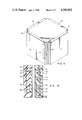
- FIG. 1 is a perspective view of a safety device equipped with a series of shields each of which has an electrical interlock.
- FIG. 1A is a fragmentary, sectional view of a safety shield electrical interlock showing an exemplary encoder and decoder.
- FIG. 2 is a schematic diagram indicating an encoding switch arrangement and a balanced bridge detecting circuit.
- FIG. 1 there is depicted a representation of an item of equipment 10, such as a spinwelder or the like, which includes moving, spinning, cutting, welding or other such elements (not illustrated) or which otherwise presents potential user hazards when in operation.
- safety shields 12, 14, 16 and 18 are provided.
- the shields may of course assume any convenient configuration consistent with the shape and functions of the equipment 10.
- the movable shields 12-18 may be made of shatterproof plastic or any such suitable material.
- ferric metal should not be used for the shield members.
- a separate electrical interlock will preferably be provided for each shield.
- the shields may be conveniently arranged to pivot open about a hinge 20 for easy access to the inside of the equipment 10 as necessary.
- Each shield is preferably provided with an electrical interlock 22, 24 which will be further described in connection with FIG. 1A wherein elements corresponding to those in FIG. 1 are similarly numbered.
- the circuit elements in FIG. 1A are exaggerated for clarity and the size, shapes and relative position of the devices depicted should not be construed to represent those of the actual device.
- An encoded switch, 24 is provided on the equipment 10 such as on a structural post of a spinwelder.
- the switch 24 cooperates with a decoder magnet arrangement 22 on a shield. While the encoder section is shown on the stationary element and the decoder on the movable shield, it will be apparent to the artisan that the configuration can be reversed. Since the encoder 24, as explained below, may be connected to additional equipment through terminals A and B, it is preferable to position it on the stationary (i.e. equipment 10) side.
- the encoder preferably contains three or more reed switches, S1-S4.
- the encoder is preferably encapsulated or potted within an opaque mounting case 26. Therefore, the arrangement of the switches is not visible to the equipment user.
- the decoder, or activating magnetic bar 22, like the encoder, is encapsulated in an opaque casing 28.
- the magnet bar is coded with the same arrangement as the encoded switches.
- the pattern of the magnets M1-M3 is not visible.
- the reed switches are selected to be of appropriate sensitivity and the magnets are small enough so that only the decoder bar 22 which is keyed to the encoder 24 will operate to close the normally open switches S1, S3 and S4 to complete the circuit between terminals A and B when the shield 12 is placed in proximity with the equipment 10.
- a normally closed reed switch S2 may be provided. This switch is arranged to open, and therefore maintain the interlock, if such an attempt is made to defeat the system.
- a precision resistor R1 may be encapsulated into the encoder 24 in order to defeat any attempt to bypass the switch assembly by shorting it out.
- the interfacing system, as described below, may be made responsive to the value of the resistance.
- the value of the precision resistor R1 should be known only to the equipment manufacturer or authorized operator personnel.
- any attempt to bypass the encoder switch assembly or to disconnect it from the system will result in an open circuit across terminals A-B when the system is energized.
- An open circuit will also result if any door is opened. Only when the encoder and decoder have not been tampered with and the safety shield is securely closed and aligned with the equipment 10, will the terminals A-B have the proper resistance or signal thereacross.
- the encoder/decoder switch system described above is used in connection with a circuit which can detect when a shield is opened or when the system has been tampered with.
- a system may be of the type shown in FIG. 2.
- the equipment is provided with four shields or windows W-1 to W-4.
- Each shield may have an encoder 26.
- These encoders may be identical or, as shown in FIG. 2, may be different from each other with regard to the number of switches used, the placement of the switches, the values of the precision resistors (R1-R4 in FIG. 2) or other such variations as would suggest themselves to the artisan.
- each encoder presents only a single terminal pair from its potted enclosure. These correspond to terminals A-B, C-D, E-F and G-H in the example shown.
- the encoders are preferably connected in series thereby presenting a single terminal pair A-H to the detection circuit 30.
- the detection circuit includes a balanced bridge comprising resistors R5, R6, R7 respectively on three of the four legs and the combination of the switch assemblies connected across terminals A-H on the other leg.
- the bridge is balanced and no bridge output signal is generated.
- a zero bridge signal results in a steady output voltage being provided across terminals I-J of the bridge.
- the connection between the switch assemblies and the balanced bridge, indicated at 32 and 34 is not accessable to be bypassed or diagnosed by the user.
- the entire bridge circuit is potted in an opaque material and preferably comprises an epoxy encapsulated printed circuit card 36 which prevents circuit diagnosis. Removal of the card 36 by the user will not defeat the interlock system since such removal will result in a zero output across terminals I-J and therefore disable the equipment.
- Adjustable resistor R8 is provided so that the total resistance of the leg of the bridge containing the encoder(s) can be balanced in accordance with the number of encoders used.
- Resistors R9 and R10 are included to provide sensitivity adjustment so that small excursions in line power will not act to trip the system and give a false indication of an open or misaligned safety shield. Essentially resistors R9 and R10 function to adjust the level at which the logic chip (as further described below) will trip.
- the balance adjustment R8 and sensitivity adjustment R10 are preferably factory set utilizing board potentiometers that are epoxy sealed after calibration. Any attempt to unseal them will therefore destroy the printed circuit card and disable the equipment.
- the sensitivity adjustment, R10 is connected to a logic chip which indicates when a shield is open or ajar or when the system has been tampered with.
- Gates 38 and 40 represent NOR gates. This configuration of double NOR gates is used as a signal buffer for low level switching. It should be appreciated that the double NOR gate is the logical equivalent of a single AND gate with its inputs tied and can be replaced by such an AND gate. In those applications where current drain from the bridge circuit to the light emitting diode, LED and its current limiting resistor R11 are not significant, the double NOR gate can be eliminated altogether.
- the NOR gate 42 merely functions as a voltage level sensor to sense the voltage across the bridge and provide an output at K depending upon the sensed voltage. As will be appreciated by the artisan, this gate could be replaced by a reverse biased transistor or other well-known voltage level detector. In operation, the gate 42 provides overvoltage detection and may be connected to an automatic shut-off device or to a master control device for controlling the equipment 10.
- the bridge is energized through terminal I-J which is connected to a regulated DC power supply, preferably of a low voltage such as 12 V DC.
- a balancing volt meter 44 may be provided if desired across bridge terminals L-M to monitor the bridge signal.
- the system may be used with door or windows which are not associated with equipment but which enclose a space to be protected, for example a room, home, store or other installation.
- the system may also be useful to align cooperating members or the like.
- the LED can be replaced by or supplemented with an enunciator such as an alarm or buzzer.
- the embodiment was chosen and described in order to best explain the principles of the invention and its practical application to thereby enable others skilled in the art to best utilize the invention in various embodiments and with various modifications as are suited to the particular use contemplated. It is intended that the scope of the invention be defined by the claims appended hereto.
Landscapes
- Engineering & Computer Science (AREA)
- General Engineering & Computer Science (AREA)
- Physics & Mathematics (AREA)
- General Physics & Mathematics (AREA)
- Mechanical Engineering (AREA)
- Automation & Control Theory (AREA)
- Transmission And Conversion Of Sensor Element Output (AREA)
- Safety Devices In Control Systems (AREA)
- Vehicle Body Suspensions (AREA)
- Switch Cases, Indication, And Locking (AREA)
- Burglar Alarm Systems (AREA)
Abstract
Description
Claims (13)
Priority Applications (6)
| Application Number | Priority Date | Filing Date | Title |
|---|---|---|---|
| US06/487,379 US4580062A (en) | 1983-04-21 | 1983-04-21 | Safety shield control device |
| NO841570A NO841570L (en) | 1983-04-21 | 1984-04-18 | SECURITY SHIELD REGULATION SYSTEM |
| AU27097/84A AU2709784A (en) | 1983-04-21 | 1984-04-19 | Interlocking switching system |
| EP84630065A EP0127561A1 (en) | 1983-04-21 | 1984-04-19 | Safety shield control device |
| KR1019840002158A KR850002336A (en) | 1983-04-21 | 1984-04-21 | Safety shield control |
| JP59079372A JPS6034597A (en) | 1983-04-21 | 1984-04-21 | Controller for safety shield |
Applications Claiming Priority (1)
| Application Number | Priority Date | Filing Date | Title |
|---|---|---|---|
| US06/487,379 US4580062A (en) | 1983-04-21 | 1983-04-21 | Safety shield control device |
Publications (1)
| Publication Number | Publication Date |
|---|---|
| US4580062A true US4580062A (en) | 1986-04-01 |
Family
ID=23935506
Family Applications (1)
| Application Number | Title | Priority Date | Filing Date |
|---|---|---|---|
| US06/487,379 Expired - Fee Related US4580062A (en) | 1983-04-21 | 1983-04-21 | Safety shield control device |
Country Status (6)
| Country | Link |
|---|---|
| US (1) | US4580062A (en) |
| EP (1) | EP0127561A1 (en) |
| JP (1) | JPS6034597A (en) |
| KR (1) | KR850002336A (en) |
| AU (1) | AU2709784A (en) |
| NO (1) | NO841570L (en) |
Cited By (22)
| Publication number | Priority date | Publication date | Assignee | Title |
|---|---|---|---|---|
| US4945340A (en) * | 1989-04-25 | 1990-07-31 | Pittway Corporation | Tamper-resistant magnetic security system |
| US5096147A (en) * | 1990-11-19 | 1992-03-17 | Sel Division, Alcatel Canada Inc. | In-circuit contact monitor |
| US5109199A (en) * | 1989-03-18 | 1992-04-28 | Daimler-Benz Ag | Seat belt buckle monitor switch having cooperative circuit |
| US5141380A (en) * | 1990-11-19 | 1992-08-25 | Daifuku Co., Ltd. | Safety arrangement for automatic warehousing facility |
| US5153589A (en) * | 1988-06-29 | 1992-10-06 | Ncr Corporation | Data processing terminal with removable keyboard module |
| US5289255A (en) * | 1991-03-28 | 1994-02-22 | Minnesota Mining And Manufacturing Co. | Cuvette for use in making a measurement of a blood parameter and assembly utilizing the same |
| US5308436A (en) * | 1993-07-03 | 1994-05-03 | Moore Business Forms, Inc. | Repair inserter sealer |
| US5541562A (en) * | 1994-10-16 | 1996-07-30 | Honeywell Inc. | Apparatus for sensing the closure of a door |
| US5673021A (en) * | 1996-05-22 | 1997-09-30 | Woods; Randall | Magnetic switch assembly for detecting unauthorized opening of doors or windows |
| US20080224803A1 (en) * | 2007-03-13 | 2008-09-18 | Omron Corporation | Switch |
| US20100055549A1 (en) * | 2008-09-02 | 2010-03-04 | Rodney Corder | Intrinsically Safe Battery Pack and System |
| US20110062793A1 (en) * | 2008-03-17 | 2011-03-17 | Powermat Ltd. | Transmission-guard system and method for an inductive power supply |
| US20110098845A1 (en) * | 2002-06-14 | 2011-04-28 | Cummins-Allison Corp. | Coin redemption machine having gravity feed coin input tray and foreign object detection system |
| US20150192054A1 (en) * | 2012-12-24 | 2015-07-09 | Ford Global Technologies, Llc | Capacitance-based vehicular component protection systems and configurations |
| US9331750B2 (en) | 2008-03-17 | 2016-05-03 | Powermat Technologies Ltd. | Wireless power receiver and host control interface thereof |
| US9337902B2 (en) | 2008-03-17 | 2016-05-10 | Powermat Technologies Ltd. | System and method for providing wireless power transfer functionality to an electrical device |
| USD763716S1 (en) * | 2014-11-25 | 2016-08-16 | Armec S.N.C. Diluigiarbore E C. | Protection cover for test equipment, in particular, for testing turbomachine rotors |
| US9493085B2 (en) | 2011-10-27 | 2016-11-15 | Ford Global Technologies, Llc | Vehicular charging and protection systems |
| US9960640B2 (en) | 2008-03-17 | 2018-05-01 | Powermat Technologies Ltd. | System and method for regulating inductive power transmission |
| US9960642B2 (en) | 2008-03-17 | 2018-05-01 | Powermat Technologies Ltd. | Embedded interface for wireless power transfer to electrical devices |
| US11387688B2 (en) | 2008-07-02 | 2022-07-12 | Powermat Technologies, Ltd. | System and method for coded communication signals regulating inductive power transmissions |
| US11979201B2 (en) | 2008-07-02 | 2024-05-07 | Powermat Technologies Ltd. | System and method for coded communication signals regulating inductive power transmissions |
Families Citing this family (7)
| Publication number | Priority date | Publication date | Assignee | Title |
|---|---|---|---|---|
| AU5420790A (en) * | 1989-04-14 | 1990-11-16 | Eja Engineering Company Limited | Safety switch assembly |
| IT1242596B (en) * | 1990-10-18 | 1994-05-16 | Gd Spa | SAFETY AND PROTECTION DEVICE OF THE DRYING AND WELDING GROUP OF AT LEAST ONE CONTINUOUS CIGARETTE BACON IN PACKAGING MACHINES. |
| BE1006793A5 (en) * | 1993-03-22 | 1994-12-13 | Pinket Dirk | High reliability security detection |
| FR2789204B1 (en) * | 1999-02-03 | 2001-03-09 | Btinternat | ELECTRONIC DEVICE FOR MONITORING AND MEMORIZING FAULT IN OPENING SECURITY LINES |
| US7714716B2 (en) | 2007-07-25 | 2010-05-11 | Robert Bosch Gmbh | Coded security sensor for a door |
| DE102011106737B4 (en) | 2011-06-28 | 2023-03-09 | Ofa Bamberg Gmbh | Compression stockings with ventilation channels and anti-slip profile |
| EP2871402B1 (en) * | 2013-11-08 | 2016-05-25 | Sick Ag | Modular safety switch |
Citations (6)
| Publication number | Priority date | Publication date | Assignee | Title |
|---|---|---|---|---|
| US3813663A (en) * | 1972-11-10 | 1974-05-28 | D Perkins | Electrical locking alarm system |
| US3825920A (en) * | 1972-11-16 | 1974-07-23 | Sierracin Corp | Laminated security window system |
| US3864173A (en) * | 1972-04-26 | 1975-02-04 | Hans Butschkau | Electric battery provided with a safeguard against short-circuitings |
| US4335376A (en) * | 1979-04-12 | 1982-06-15 | Marquardt Ralph E | Electronic control device |
| US4349814A (en) * | 1979-10-08 | 1982-09-14 | Duraplug Electricals Limited | Electric switches |
| US4420745A (en) * | 1978-12-05 | 1983-12-13 | Societe Anonyme Trefilunion | Security system |
Family Cites Families (5)
| Publication number | Priority date | Publication date | Assignee | Title |
|---|---|---|---|---|
| DE1061660B (en) * | 1957-05-31 | 1959-07-16 | Siemens Ag | Electrical fuse arrangement |
| DE1161183B (en) * | 1960-08-26 | 1964-01-09 | Siemens Ag | Circuit arrangement to protect against break-ins and theft |
| FR2336659A1 (en) * | 1975-12-24 | 1977-07-22 | Lynx Alarm | Magnetic displacement detector for burglar alarm systems - comprises three switches, with principal magnet and keeping magnet |
| FR2438253B2 (en) * | 1978-10-06 | 1986-11-28 | Lynx Alarm | MAGNETIC DETECTOR FOR THE RELATIVE MOVEMENT OF TWO OBJECTS, IN PARTICULAR AN OPENING DETECTOR FOR PROTECTION SYSTEMS |
| FR2526519A1 (en) * | 1982-05-05 | 1983-11-10 | Cousin Pierre | SAFETY DEVICE FOR STARTING AN ELECTRICAL APPARATUS |
-
1983
- 1983-04-21 US US06/487,379 patent/US4580062A/en not_active Expired - Fee Related
-
1984
- 1984-04-18 NO NO841570A patent/NO841570L/en unknown
- 1984-04-19 AU AU27097/84A patent/AU2709784A/en not_active Abandoned
- 1984-04-19 EP EP84630065A patent/EP0127561A1/en not_active Withdrawn
- 1984-04-21 JP JP59079372A patent/JPS6034597A/en active Pending
- 1984-04-21 KR KR1019840002158A patent/KR850002336A/en not_active Application Discontinuation
Patent Citations (6)
| Publication number | Priority date | Publication date | Assignee | Title |
|---|---|---|---|---|
| US3864173A (en) * | 1972-04-26 | 1975-02-04 | Hans Butschkau | Electric battery provided with a safeguard against short-circuitings |
| US3813663A (en) * | 1972-11-10 | 1974-05-28 | D Perkins | Electrical locking alarm system |
| US3825920A (en) * | 1972-11-16 | 1974-07-23 | Sierracin Corp | Laminated security window system |
| US4420745A (en) * | 1978-12-05 | 1983-12-13 | Societe Anonyme Trefilunion | Security system |
| US4335376A (en) * | 1979-04-12 | 1982-06-15 | Marquardt Ralph E | Electronic control device |
| US4349814A (en) * | 1979-10-08 | 1982-09-14 | Duraplug Electricals Limited | Electric switches |
Cited By (35)
| Publication number | Priority date | Publication date | Assignee | Title |
|---|---|---|---|---|
| US5153589A (en) * | 1988-06-29 | 1992-10-06 | Ncr Corporation | Data processing terminal with removable keyboard module |
| US5109199A (en) * | 1989-03-18 | 1992-04-28 | Daimler-Benz Ag | Seat belt buckle monitor switch having cooperative circuit |
| US4945340A (en) * | 1989-04-25 | 1990-07-31 | Pittway Corporation | Tamper-resistant magnetic security system |
| US5096147A (en) * | 1990-11-19 | 1992-03-17 | Sel Division, Alcatel Canada Inc. | In-circuit contact monitor |
| US5141380A (en) * | 1990-11-19 | 1992-08-25 | Daifuku Co., Ltd. | Safety arrangement for automatic warehousing facility |
| US5289255A (en) * | 1991-03-28 | 1994-02-22 | Minnesota Mining And Manufacturing Co. | Cuvette for use in making a measurement of a blood parameter and assembly utilizing the same |
| US5308436A (en) * | 1993-07-03 | 1994-05-03 | Moore Business Forms, Inc. | Repair inserter sealer |
| US5541562A (en) * | 1994-10-16 | 1996-07-30 | Honeywell Inc. | Apparatus for sensing the closure of a door |
| US5673021A (en) * | 1996-05-22 | 1997-09-30 | Woods; Randall | Magnetic switch assembly for detecting unauthorized opening of doors or windows |
| US8607957B2 (en) * | 2002-06-14 | 2013-12-17 | Cummins-Allison Corp. | Coin redemption machine having gravity feed coin input tray and foreign object detection system |
| US20110098845A1 (en) * | 2002-06-14 | 2011-04-28 | Cummins-Allison Corp. | Coin redemption machine having gravity feed coin input tray and foreign object detection system |
| US20080224803A1 (en) * | 2007-03-13 | 2008-09-18 | Omron Corporation | Switch |
| DE102008010226B4 (en) * | 2007-03-13 | 2018-12-13 | Omron Corp. | switch |
| US7999644B2 (en) | 2007-03-13 | 2011-08-16 | Omron Corporation | Switch |
| US9035501B2 (en) | 2008-03-17 | 2015-05-19 | Powermat Technologies, Ltd. | System and method for providing simple feedback signals indicating if more or less power is required during inductive power transmission |
| US9960640B2 (en) | 2008-03-17 | 2018-05-01 | Powermat Technologies Ltd. | System and method for regulating inductive power transmission |
| US20110062793A1 (en) * | 2008-03-17 | 2011-03-17 | Powermat Ltd. | Transmission-guard system and method for an inductive power supply |
| US9048696B2 (en) | 2008-03-17 | 2015-06-02 | Powermat Technologies, Ltd. | Transmission-guard system and method for an inductive power supply |
| US10033231B2 (en) | 2008-03-17 | 2018-07-24 | Powermat Technologies Ltd. | System and method for providing wireless power transfer functionality to an electrical device |
| US9083204B2 (en) | 2008-03-17 | 2015-07-14 | Powermat Technologies, Ltd. | Transmission-guard system and method for an inductive power supply |
| US9136734B2 (en) * | 2008-03-17 | 2015-09-15 | Powermat Technologies, Ltd. | Transmission-guard system and method for an inductive power supply |
| US9331750B2 (en) | 2008-03-17 | 2016-05-03 | Powermat Technologies Ltd. | Wireless power receiver and host control interface thereof |
| US9337902B2 (en) | 2008-03-17 | 2016-05-10 | Powermat Technologies Ltd. | System and method for providing wireless power transfer functionality to an electrical device |
| US11837399B2 (en) | 2008-03-17 | 2023-12-05 | Powermat Technologies, Ltd. | Transmission-guard system and method for an inductive power supply |
| US9960642B2 (en) | 2008-03-17 | 2018-05-01 | Powermat Technologies Ltd. | Embedded interface for wireless power transfer to electrical devices |
| US10205346B2 (en) | 2008-03-17 | 2019-02-12 | Powermat Technologies Ltd. | Wireless power receiver and host control interface thereof |
| US9685795B2 (en) | 2008-03-17 | 2017-06-20 | Powermat Technologies Ltd. | Transmission-guard system and method for an inductive power supply |
| US11979201B2 (en) | 2008-07-02 | 2024-05-07 | Powermat Technologies Ltd. | System and method for coded communication signals regulating inductive power transmissions |
| US11387688B2 (en) | 2008-07-02 | 2022-07-12 | Powermat Technologies, Ltd. | System and method for coded communication signals regulating inductive power transmissions |
| US20100055549A1 (en) * | 2008-09-02 | 2010-03-04 | Rodney Corder | Intrinsically Safe Battery Pack and System |
| US8129046B2 (en) | 2008-09-02 | 2012-03-06 | Dwyer Instruments, Inc. | Intrinsically safe battery pack and system |
| US9493085B2 (en) | 2011-10-27 | 2016-11-15 | Ford Global Technologies, Llc | Vehicular charging and protection systems |
| US9631541B2 (en) * | 2012-12-24 | 2017-04-25 | Ford Global Technologies, Llc | Capacitance-based vehicular component protection systems and configurations |
| US20150192054A1 (en) * | 2012-12-24 | 2015-07-09 | Ford Global Technologies, Llc | Capacitance-based vehicular component protection systems and configurations |
| USD763716S1 (en) * | 2014-11-25 | 2016-08-16 | Armec S.N.C. Diluigiarbore E C. | Protection cover for test equipment, in particular, for testing turbomachine rotors |
Also Published As
| Publication number | Publication date |
|---|---|
| KR850002336A (en) | 1985-05-10 |
| AU2709784A (en) | 1984-10-25 |
| EP0127561A1 (en) | 1984-12-05 |
| NO841570L (en) | 1984-10-22 |
| JPS6034597A (en) | 1985-02-22 |
Similar Documents
| Publication | Publication Date | Title |
|---|---|---|
| US4580062A (en) | Safety shield control device | |
| US4349814A (en) | Electric switches | |
| US3829850A (en) | Proximity detector | |
| US3161742A (en) | Magnetic intruder and fire deterctor | |
| US4812674A (en) | Safety gate limit switch using Hall effect transducer | |
| CA1321417C (en) | Apparatus and method for protecting the contacts of an electrical switch from current surges | |
| US4698621A (en) | Circuit breaker panels with alarm system | |
| US2877361A (en) | Burglar alarm system | |
| US3896425A (en) | Proximity detector | |
| US3506906A (en) | Ground fault circuit interrupter with inadvertent ground sensor | |
| US5233323A (en) | Defeat resistant interlock/monitoring system | |
| US3737765A (en) | Isolated power ground fault detector system | |
| NL8502553A (en) | IMPROVED PANELS FOR CIRCUIT BREAKERS WITH ALARM SYSTEMS. | |
| CA1145008A (en) | Intrusion detecting switch | |
| US4348661A (en) | Self-balancing alarm system | |
| US3588865A (en) | Security alarm system | |
| US4340852A (en) | Scanning system using alternating current for indicating the open, closed and ground condition of a contact | |
| EP0123641A2 (en) | Improved safety shield control system | |
| US4979069A (en) | Motor fault detector with optical isolation | |
| US5173831A (en) | Neutral line circuit interrupter | |
| GB2407126A (en) | Magnetic safety interlock and monitoring circuit | |
| DK0385206T3 (en) | Safety container | |
| US3617809A (en) | Electronic safety system | |
| US3439359A (en) | Alarm system for preventing the theet of valuable articles | |
| US3737744A (en) | Body detecting industrial safety system |
Legal Events
| Date | Code | Title | Description |
|---|---|---|---|
| AS | Assignment |
Owner name: COSDEN TECHNOLOGY, INC., DALLAS TX, A CORP OF DE Free format text: ASSIGNMENT OF ASSIGNORS INTEREST.;ASSIGNOR:MACLAUGHLIN, DONALD N.;REEL/FRAME:004244/0955 Effective date: 19830412 |
|
| AS | Assignment |
Owner name: PACKAGING RESOURCES, INC., A CORP. OF DE Free format text: ASSIGNMENT OF ASSIGNORS INTEREST.;ASSIGNORS:FINA OIL AND CHEMICAL COMPANY;COSDEN TECHNOLOGY, INC.;REEL/FRAME:004849/0215 Effective date: 19871208 Owner name: COSDEN OIL & CHEMICAL COMPANY Free format text: MERGER;ASSIGNORS:VERCON, INC., A DE CORP.;EMEJOTA ENGINEERING CORP.;REEL/FRAME:004849/0206 Effective date: 19860403 Owner name: AMERICAN PETROFINA COMPANY OF TEXAS Free format text: MERGER;ASSIGNORS:COSDEN OIL & CHEMICAL COMPANY;SIGMA COATINGS INC.;AMERICAN PETROFINA MARKETING, INC., A DE CORP.;AND OTHERS;REEL/FRAME:004849/0209 Effective date: 19860826 Owner name: FINA OIL AND CHEMICAL COMPANY Free format text: CHANGE OF NAME;ASSIGNOR:AMERICAN PETROFINA COMPANY OF TEXAS;REEL/FRAME:004849/0212 Effective date: 19860528 |
|
| FPAY | Fee payment |
Year of fee payment: 4 |
|
| FEPP | Fee payment procedure |
Free format text: PAYOR NUMBER ASSIGNED (ORIGINAL EVENT CODE: ASPN); ENTITY STATUS OF PATENT OWNER: LARGE ENTITY |
|
| FPAY | Fee payment |
Year of fee payment: 8 |
|
| AS | Assignment |
Owner name: PACKAGING RESOURCES INCORPORATED, ILLINOIS Free format text: ASSIGNMENT FOR RELEASE OF SECURITY;ASSIGNOR:SECURITY PACIFIC BUSINESS CREDIT INC.;REEL/FRAME:006667/0051 Effective date: 19930630 Owner name: UNION BANK OF SWITZERLAND, NEW YORK BRANCH, AS AGE Free format text: ASSIGNMENT FOR SECURITY;ASSIGNOR:PACKAGING RESOURCES INCORPORATED;REEL/FRAME:006667/0075 Effective date: 19930630 |
|
| REMI | Maintenance fee reminder mailed | ||
| LAPS | Lapse for failure to pay maintenance fees | ||
| FP | Lapsed due to failure to pay maintenance fee |
Effective date: 19980401 |
|
| STCH | Information on status: patent discontinuation |
Free format text: PATENT EXPIRED DUE TO NONPAYMENT OF MAINTENANCE FEES UNDER 37 CFR 1.362 |