US4573754A - Lamp assembly - Google Patents
Lamp assembly Download PDFInfo
- Publication number
- US4573754A US4573754A US06/589,365 US58936584A US4573754A US 4573754 A US4573754 A US 4573754A US 58936584 A US58936584 A US 58936584A US 4573754 A US4573754 A US 4573754A
- Authority
- US
- United States
- Prior art keywords
- cavity
- socket
- connector
- assembly
- base
- Prior art date
- Legal status (The legal status is an assumption and is not a legal conclusion. Google has not performed a legal analysis and makes no representation as to the accuracy of the status listed.)
- Expired - Lifetime
Links
- 239000004020 conductor Substances 0.000 claims abstract description 94
- 238000005192 partition Methods 0.000 claims abstract description 20
- 239000000463 material Substances 0.000 claims abstract description 15
- 238000007789 sealing Methods 0.000 claims description 28
- 238000003780 insertion Methods 0.000 claims description 20
- 230000037431 insertion Effects 0.000 claims description 20
- 230000000712 assembly Effects 0.000 claims description 5
- 238000000429 assembly Methods 0.000 claims description 5
- 229920000728 polyester Polymers 0.000 claims description 4
- 229920002635 polyurethane Polymers 0.000 claims description 3
- 239000004814 polyurethane Substances 0.000 claims description 3
- 230000000694 effects Effects 0.000 claims description 2
- 230000002093 peripheral effect Effects 0.000 claims 9
- 239000003989 dielectric material Substances 0.000 claims 7
- 239000011324 bead Substances 0.000 claims 4
- 239000012858 resilient material Substances 0.000 claims 4
- 239000007779 soft material Substances 0.000 claims 1
- 238000000638 solvent extraction Methods 0.000 claims 1
- 239000013536 elastomeric material Substances 0.000 abstract 1
- 229920003023 plastic Polymers 0.000 description 6
- 239000004033 plastic Substances 0.000 description 6
- 238000000034 method Methods 0.000 description 5
- 238000010276 construction Methods 0.000 description 3
- 238000013461 design Methods 0.000 description 3
- 239000004519 grease Substances 0.000 description 3
- 238000012856 packing Methods 0.000 description 3
- ISWSIDIOOBJBQZ-UHFFFAOYSA-N phenol group Chemical group C1(=CC=CC=C1)O ISWSIDIOOBJBQZ-UHFFFAOYSA-N 0.000 description 3
- DMFGNRRURHSENX-UHFFFAOYSA-N beryllium copper Chemical compound [Be].[Cu] DMFGNRRURHSENX-UHFFFAOYSA-N 0.000 description 2
- 238000006073 displacement reaction Methods 0.000 description 2
- 239000011521 glass Substances 0.000 description 2
- 238000004382 potting Methods 0.000 description 2
- HRPVXLWXLXDGHG-UHFFFAOYSA-N Acrylamide Chemical compound NC(=O)C=C HRPVXLWXLXDGHG-UHFFFAOYSA-N 0.000 description 1
- JOYRKODLDBILNP-UHFFFAOYSA-N Ethyl urethane Chemical compound CCOC(N)=O JOYRKODLDBILNP-UHFFFAOYSA-N 0.000 description 1
- 238000004891 communication Methods 0.000 description 1
- 150000001875 compounds Chemical class 0.000 description 1
- 230000007797 corrosion Effects 0.000 description 1
- 238000005260 corrosion Methods 0.000 description 1
- 230000006378 damage Effects 0.000 description 1
- 230000003028 elevating effect Effects 0.000 description 1
- 238000005538 encapsulation Methods 0.000 description 1
- 238000010438 heat treatment Methods 0.000 description 1
- 238000005286 illumination Methods 0.000 description 1
- 238000004519 manufacturing process Methods 0.000 description 1
- 238000003825 pressing Methods 0.000 description 1
- 239000000126 substance Substances 0.000 description 1
Images

Classifications
-
- H—ELECTRICITY
- H01—ELECTRIC ELEMENTS
- H01R—ELECTRICALLY-CONDUCTIVE CONNECTIONS; STRUCTURAL ASSOCIATIONS OF A PLURALITY OF MUTUALLY-INSULATED ELECTRICAL CONNECTING ELEMENTS; COUPLING DEVICES; CURRENT COLLECTORS
- H01R33/00—Coupling devices specially adapted for supporting apparatus and having one part acting as a holder providing support and electrical connection via a counterpart which is structurally associated with the apparatus, e.g. lamp holders; Separate parts thereof
- H01R33/965—Dustproof, splashproof, drip-proof, waterproof, or flameproof holders
-
- H—ELECTRICITY
- H01—ELECTRIC ELEMENTS
- H01R—ELECTRICALLY-CONDUCTIVE CONNECTIONS; STRUCTURAL ASSOCIATIONS OF A PLURALITY OF MUTUALLY-INSULATED ELECTRICAL CONNECTING ELEMENTS; COUPLING DEVICES; CURRENT COLLECTORS
- H01R33/00—Coupling devices specially adapted for supporting apparatus and having one part acting as a holder providing support and electrical connection via a counterpart which is structurally associated with the apparatus, e.g. lamp holders; Separate parts thereof
- H01R33/05—Two-pole devices
- H01R33/06—Two-pole devices with two current-carrying pins, blades or analogous contacts, having their axes parallel to each other
- H01R33/09—Two-pole devices with two current-carrying pins, blades or analogous contacts, having their axes parallel to each other for baseless lamp bulb
-
- Y—GENERAL TAGGING OF NEW TECHNOLOGICAL DEVELOPMENTS; GENERAL TAGGING OF CROSS-SECTIONAL TECHNOLOGIES SPANNING OVER SEVERAL SECTIONS OF THE IPC; TECHNICAL SUBJECTS COVERED BY FORMER USPC CROSS-REFERENCE ART COLLECTIONS [XRACs] AND DIGESTS
- Y10—TECHNICAL SUBJECTS COVERED BY FORMER USPC
- Y10S—TECHNICAL SUBJECTS COVERED BY FORMER USPC CROSS-REFERENCE ART COLLECTIONS [XRACs] AND DIGESTS
- Y10S439/00—Electrical connectors
- Y10S439/918—Multilamp vehicle panel
Definitions
- This invention relates to lamp assemblies and, more particularly, to lamp assemblies particularly suited for automotive applications.
- the invention lamp assembly includes a socket assembly, a base, and a plurality of elongated conductors.
- One end of the socket assembly is sealingly but releasably mounted in one face of the base with contacts on the mounted socket assembly end positioned in a socket cavity in the base, and the elongated conductors pass sealingly through a wall of the base to position their inboard ends in the socket cavity in respective electrical connection with the contacts of the socket assembly.
- the lamp assembly further includes a connector having a plurality of terminals adapted to respectively electrically connect with the outboard ends of the conductors.
- the connector terminals are positioned in one end of the connector; that end of the connector is sized and configured to be inserted into a connector cavity defined in the base and separated from the socket cavity by the base wall through which the elongated conductors pass; and the outboard ends of the elongated conductors are positioned in the connector cavity for respective electrical connection to the connector terminals upon insertion of the connector into the connector cavity.
- the socket assembly includes a hollow socket and a retainer element positioned within the socket and defining a rectangular cavity for receipt of a wedge base bulb.
- the rectangular bulb cavity is defined by a pair of opposing walls and at least one of the walls is defined by a yieldable finger which wedges open upon insertion of the bulb to allow passage of the leading edge of a collar on the base of the bulb and thereafter snaps back to releasably grasp the bulb collar.
- an electrical assembly in which an elongated electrical conductor element extends through a passage in a partition of a housing assembly for electrical contact at its inboard end with an electrical terminal disposed within a sealed cavity defined by the housing assembly.
- the passage tapers inwardly at its inboard end to form inwardly extending lip means and the conductor element has a thickness slightly greater than the width of the passage at the lip means and slightly less than the width of the outboard end of the passage so that the conductor element, upon insertion through the passage into the cavity, coacts with the lip means to form a tight seal for the cavity at the partition and to resist withdrawal of the conductor element through the passage.
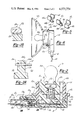
- FIG. 1 is an exploded perspective view of the invention lamp assembly
- FIG. 2 is an elevational view, in cross section, of the invention lamp assembly
- FIGS. 2A and 2B are enlarged views of selected portions of FIG. 2;
- FIG. 3 is a top view of the invention lamp assembly with certain elements of the assembly omitted for clarity of illustration;
- FIG. 4 is a bottom perspective view of a bulb retainer element employed in the invention lamp assembly
- FIG. 5 is a perspective view of electrical contact elements employed in the invention lamp assembly
- FIG. 6 is a partially fragmentary view of the invention lamp assembly shown in association with a lamp housing and parabola;
- FIGS. 7 and 8 are views of a modified moisture sealing construction.
- the invention lamp assembly broadly considered, comprises a base 10, a connector 12, a socket 14, a bulb 16, and a bulb retainer 18.
- Base 10 is formed of a resilient, plastic material such, for example, as a polyurethane or an acrylamide.
- Base 10 includes a socket cavity 10a opening at the upper face 10b of the base, and a connector cavity 10c opening in an end face 10d of the base.
- Connector cavity 10c is separated from socket cavity 10a by a wall or partition 10e.
- Three elongated conductor bars 20, 22, 24 of rectangular conductor bar stock, extend in parallel fashion within base 10. Bars 20, 22, 24 may, for example, be formed of beryllium copper material.
- One end 20a, 22a, 24a of each conductor bar is positioned in connector cavity 10c and the other end 20b, 22b, 24b of each conductor bar is supported on a platform surface 10f provided on the bottom of socket cavity 10a.
- passages 26 (FIG. 2A) extending longitudinally through partition 10e.
- Each passage 26 is rectangular in cross section and is necked down adjacent socket cavity 10a to form opposing lip portions 26a which taper outwardly in the direction of connector cavity 10b to blend with the main body portion 26b of the passage.
- Conductor bars 20, 22, 24 have a thickness that is slightly greater than the height of the opening defined between the relaxed lip portions 26a and slightly less than the height of passage portion 26b and a width that is slightly greater than the width of passage 26 so that, as the bars are selectively inserted through connector cavity 10c and through passages 26, lip portions 26a are splayed resiliently outwardly to pass the bars and allow the ends 20b, 22b, 24b to be seated on platform surface 10f.
- lip portions 26a coact with the respective upper and lower surfaces of the conductor bars and the side edges of the bars form an interference fit with the adjacent material of the base. Bars 20, 22, 24 thus form a moisture seal for socket cavity 10a at partition 10e.
- Lip portions 26a also coact with the engaged bar surfaces to resist withdrawal of the bars since any attempted withdrawal of a bar will tend to pivot lip portions 26a toward a more tightly closed clamping configuration. This arrangement prevents inadvertent withdrawal or displacement of the conductor bars while yet permitting withdrawal upon the application of a delibrate withdrawl force and, if desired, subsequent reinsertion for reassembly purposes.
- FIGS. 7 and 8 A modified sealing and clamping construction is shown in FIGS. 7 and 8 for use in applications requiring round cross section conductors rather than the flat, rectangular conductor bar stock used for conductor bars 20, 22, 24.
- circular passages 28 are provided in a partition 30 for coaction with round cross section conductors 32.
- Each passage 28 is necked down at one end to form an annular lip portion 28a which tapers outwardly toward the other end of the passage to blend with the main body cylindrical portion 28b of the passage.
- the round cross section conductor 32 has a diameter that is slightly greater than the relaxed inner diameter of annular lip portion 28a and slightly less than the diameter of main body passage portion 28b.
- lip portion 28a is splayed elastically outwardly to pass the conductor element (not shown) positioned in a cavity defined to the right of partition 30. Lip portion 28a thus coacts with the outer periphery of conductor 32 to form a moisture seal at the partition. Lip portion 28a also acts to resist withdrawal of conductor 32 since any attempted withdrawal will tend to pivot lip portion 28a toward a more tightly closed clamping configuration. This arrangement prevents inadvertent withdrawal or displacement of the conductor bars while yet permitting withdrawal upon the application of a deliberate withdrawal force and, if desired, subsequent reinsertion for reassembly purposes.
- Connector 12 is formed of a hard, rigid, plastic material such, for example, as a polyester, phenolic or the like.
- Connector 12 is generally hollow and includes an upper wall 12a, a lower wall 12b, sidewalls 12c and 12d, partitions 12e and 12f, and a locking tab 12g upstanding from top wall 12a.
- Partitions 12e and 12f coact with sidewalls 12c and 12d to define three parallel through passages 12h, 12i and 12j.
- a terminal 34 is positioned at the forward end of each passage 12h, 12i and 12j.
- a resilient tab 12k coacts with a detent in the top wall of each terminal 34 to maintain the terminal in its forward position within the connector upon insertion of a suitable tool into the forward end of the connector to resiliently raise the respective tab 12k.
- Three wires 36, 38, 40 are crimped at their forward ends to a respective terminal 34 and extend rearwardly therefrom through the appropriate passage 12h, 12i, 12j.
- Connector 12 is sized and configured to slide snugly into the connector cavity 10c of base 10 with conductor bar ends 20a, 22a, 24a each pressing firmly into a respective terminal 34 to establish a firm electrical connection between wires 36, 38, 40 and bars 20, 22, 24.
- locking tab 12 g cams upwardly over raised base portion 10g and then snaps downwardly to firmly embrace base portion 10g, firmly seat the connector in the base cavity, and preclude inadvertent withdrawal of the connector from the base.
- resilient lip portions 10h FIG. 2B
- FIG. 2B formed around the entire perimeter of the opening of cavity 10c in end face 10d, slidably and sealing wipe along upper and lower connector walls 12a, 12b and along connector sidewalls 12c and 12d to form a moisture seal between connector 12 and base 10 at the entrace to cavity 10c.
- the resilient polyurethane or the like material of lip portions 10h yield to allow insertion of the connector and conform snugly to the walls of the connector to optimize the mositure seal. If desired, wires 36, 38 and 40 may be potted into connector 12 to preclude the entry of moisture through the hollow interior of the connector.
- Socket 14 is formed of a hard, rigid, plastic material such, for example, as a polyester, phenolic or the like. Socket 14 has a tubular configuration and includes a cylindrical sidewall 14a, defining a central bore 14b, and an external collar 14c. Socket 14 is received with a snap press fit in socket opening 10a of base 10. Specifically, as socket 14 is pressed downwardly into opening 10a, the chamfered leading edge portion 14d of the socket presses resiliently past an annular lip 10i in socket opening 10a and seats in an annular seat 10j defined immediately below lip 10i.
- lip 10i seats in an annular notch seat 14e defined on socket 14 immediately above leading edge portion 14d
- collar 14c seats on the upper annular edge 10k of base rim portion 10l with a notch 14f in collar 14c embracing an upstanding post 10m on base 10 to insure proper indexing of socket 14 relative to base 10 during assembly and preclude subsequent inadvertent rotation of socket 14 relative to base 10.
- the resilient urethane or the like material of base 10 yields to allow insertion of socket 14 and conforms snugly to the inserted end of the socket to ensure an effective moisture seal for cavity 10a.
- Bulb 16 is of the wedge base type and includes a glass envelope 16a housing a double filament, a glass wedge base 16b receiving and selectively exposing elements 16c of both filaments, and an external plastic collar 42 positioned at the necked down interface of the envelope 16a and wedge base 16b.
- Bulb retainer 18 is formed of a hard, rigid, plastic material such, for example, as polyester, phenolic or the like. Bulb retainer 18 has a cylindrical, plug-like configuration and is received with a press fit in socket bore 14b to form a socket assembly. In assembled relation, the lower end 18a of the retainer projects slightly below the lower end of the socket.
- Retainer 18 includes an upstanding finger portion 18b and a rigid post portion 18c. Confronting lips 18d on finger portion 18c coact to define a generally rectangular opening 18e for receipt of bulb 16. As bulb 16 is pressed downwardly into retainer 18, wedge base 16b passes freely through opening 18e and through the opening defined between confronting rib portions 18f on post portion 18c and finger portion 18b.
- collar 42 splays finger portion 18b outwardly to allow the collar to pass, whereafter finger portion 18b snaps back to firmly grasp the collar.
- confronting lips 18d embrace the bulb envelope 16a immediately above collar 42
- confronting ribs 18f embrace the bulb base 16b immediately below collar 42
- wedge base 16b extends downwardly into a bulb cavity 18g defined between post portion 18c and finger portion 18b below ribs 18f.
- contact 44 includes a yoked upper end 44a, a bridge portion 44b, and a lower end 44c.
- Yoked upper end 44a embraces both sides of bulb base 16 and establishes electrical connection with exposed elements 16c of both bulb filaments.
- Lower end 44c establishes electrical connection with conductor bar 20.
- Contact 46 includes an upper end 46a, a bridge portion 46b, and a lower end 46c.
- Upper end 46a is positioned at one side of bulb base 16 to establish electrical connection with an exposed filament 16c of one of the bulb filaments and lower end 46c contacts conductor bar 22. Contact 46 thus establishes electrical connection between conductor bar 22 and one filament of bulb 16.
- Contact 48 includes an upper end 48a, a bridge portion 48b, and a lower end 48c. Upper end 48a is positioned at the other side of bulb base 16 to establish electrical connection with an exposed element 16c of the other bulb filament and lower end 48c contacts conductor bar 24. Contact 48 thus establishes electrical connection between conductor bar 24 and the other filament of bulb 16. Either filament of bulb 16 may thus be powered by powering the appropriate wire 38, 40.
- Contacts 44, 46, 48 are preferably formed of a beryllium copper material.
- the invention lamp assembly is seen in FIG. 6 in a typical lamp environment such, for example, as an automotive tail lamp assembly.
- the invention lamp assembly is mounted with a twisting movement in the housing 50 of the tail lamp with cam members 14g on socket 14 coacting with suitable grooves in housing 50 to securely mount the lamp assembly in the housing.
- envelope portion 16a of bulb 16 is positioned within lamp parabola 52 to provide the required tail lamp illumination.
- the heat generated by bulb 16 has the effect of heating the lamp assembly and, specifically, significantly elevating the temperature of the air in cavity 10a.
- the air in cavity 10a cools and contracts to form a vacuum condition in the cavity.
- the vacuum condition in cavity 10a operates to attempt to suck moisture laden air into the cavity. If moisture is thus introduced into the cavity, galvanic action occurs at the interface of contacts 44, 46, 48 and conductors 20, 22, 24 and the resulting corrosion eventually renders the lamp inoperative.
- Introduction of moisture into cavity 10a is effectively precluded, however, in the invention lamp assembly by the mechanical interference seal formed at the interface of socket 14 in base 10 and at the point of passage of conductors 20, 22, 24 through partition 10e. Moisture sealing of the lamp assembly is further facilitated by the mechanical interference fit between the base and the connector.
- the invention lamp assembly thus achieves effective moisture sealing by purely mechanical means and provides component parts which are readily assembled and disassembled. Since the invention lamp assembly achieves effective moisture sealing without resort to potting or grease packing, the lamp assembly may be selectively assembled in the specific manner or sequence that is most compatible with the assembly process of the apparatus or machine of which the lamp assembly will become a part. In the case of a tail lamp assembly for an automobile where the location of the lamp housing and of the vehicular wiring harness are essentially givens dictated by various automotive design and styling parameters, the various components of the invention lamp assembly may be selectively assembled, either by the parts supplier or by the orginal equipment manufacturer, in whatever sequence is most compatible with the total automotive assembly process and may be selectively connected to the lamp housing and to the wiring harness in whatever manner is most consistent with optimal assembly efficiency.
- the invention lamp assembly also allows later disassembly for repair without destroying the moisture seal, since the moisture seal is reestablished whenever the various components are reassembled.
- the invention lamp assembly provides greater flexibility in the original assembly process, allows later repair without destruction of the moisture seal, provides a more effective moisture seal, and allows economy of manufacture by eliminating the labor and materials required to achieve the encapsulation or packing.
Landscapes
- Fastening Of Light Sources Or Lamp Holders (AREA)
- Non-Portable Lighting Devices Or Systems Thereof (AREA)
- Connecting Device With Holders (AREA)
Priority Applications (4)
| Application Number | Priority Date | Filing Date | Title |
|---|---|---|---|
| US06/589,365 US4573754A (en) | 1984-03-14 | 1984-03-14 | Lamp assembly |
| JP59281859A JPS60195886A (ja) | 1984-03-14 | 1984-12-27 | ランプ組立体 |
| CA000476353A CA1212160A (en) | 1984-03-14 | 1985-03-13 | Lamp assembly |
| EP85301720A EP0155181A3 (de) | 1984-03-14 | 1985-03-13 | Lampenanordnung |
Applications Claiming Priority (1)
| Application Number | Priority Date | Filing Date | Title |
|---|---|---|---|
| US06/589,365 US4573754A (en) | 1984-03-14 | 1984-03-14 | Lamp assembly |
Publications (1)
| Publication Number | Publication Date |
|---|---|
| US4573754A true US4573754A (en) | 1986-03-04 |
Family
ID=24357711
Family Applications (1)
| Application Number | Title | Priority Date | Filing Date |
|---|---|---|---|
| US06/589,365 Expired - Lifetime US4573754A (en) | 1984-03-14 | 1984-03-14 | Lamp assembly |
Country Status (4)
| Country | Link |
|---|---|
| US (1) | US4573754A (de) |
| EP (1) | EP0155181A3 (de) |
| JP (1) | JPS60195886A (de) |
| CA (1) | CA1212160A (de) |
Cited By (45)
| Publication number | Priority date | Publication date | Assignee | Title |
|---|---|---|---|---|
| US4630877A (en) * | 1985-11-15 | 1986-12-23 | Microdot Inc. | Socket |
| US4653841A (en) * | 1986-02-14 | 1987-03-31 | General Motors Corporation | Low profile wedge base lamp bulb socket assembly |
| US4772217A (en) * | 1987-06-30 | 1988-09-20 | Augat Inc. | Pressure sensor connector system |
| US4795373A (en) * | 1987-05-15 | 1989-01-03 | Cooper Industries, Inc. | Lamp with plastic base |
| US4940422A (en) * | 1989-05-17 | 1990-07-10 | Zanxx, Inc. | Low profile lamp socket assembly |
| US4958429A (en) * | 1989-05-17 | 1990-09-25 | Zanxx, Inc. | Method of making low profile lamp socket assembly |
| US5000702A (en) * | 1989-05-17 | 1991-03-19 | Zanxx, Inc. | Low profile lamp socket assembly and method of making |
| US5029057A (en) * | 1989-11-20 | 1991-07-02 | Gte Products Corporation | Clipped together lamp base |
| US5035643A (en) * | 1989-05-17 | 1991-07-30 | Zanxx, Inc. | Axial low profile lamp socket assembly |
| US5041955A (en) * | 1989-11-20 | 1991-08-20 | Gte Products Corporation | Vibration resistant lamp base |
| US5411407A (en) * | 1994-09-02 | 1995-05-02 | Osram Sylvania Inc. | Lamp socket |
| USD360616S (en) | 1993-07-07 | 1995-07-25 | Sumitomo Wiring Systems, Ltd. | Electric socket for motorcar |
| US5479066A (en) * | 1993-03-31 | 1995-12-26 | U.S. Philips Corporation | Electric lamp |
| US5584156A (en) * | 1993-07-16 | 1996-12-17 | Lange; Fredric | Modular structural framing system |
| US5588274A (en) * | 1993-07-16 | 1996-12-31 | Lange; Fredric | Modular structural framing system |
| US5706622A (en) * | 1994-06-10 | 1998-01-13 | Lange; Fredric | Modular structural framing system |
| US5709571A (en) * | 1996-02-20 | 1998-01-20 | Yazaki Corporation | Wedge-base lamp socket with terminal cover |
| US5800183A (en) * | 1996-02-22 | 1998-09-01 | Tricon Industries Incorporated | Sealed socket assembly for a plug-in lamp and a method for assembling same |
| US6083055A (en) * | 1998-12-10 | 2000-07-04 | Chuang; Te-Chun | Lamp assembly |
| US6224415B1 (en) * | 2000-02-11 | 2001-05-01 | James W Gibboney, Jr. | Locking light socket and light |
| US6386903B1 (en) * | 2000-09-28 | 2002-05-14 | General Motors Corporation | Terminal position assurance assembly for roof marker lamp |
| US6467942B2 (en) | 2001-01-12 | 2002-10-22 | Alcoa Fujikura Limited | Automotive lamp socket |
| FR2829304A1 (fr) * | 2001-08-31 | 2003-03-07 | Valeo Vision | Agencement pour la connexion electrique d'une lampe |
| US20030068929A1 (en) * | 2001-10-04 | 2003-04-10 | Guide Corporation | Wedge base sealed lamp socket |
| US6632100B1 (en) | 1997-04-23 | 2003-10-14 | Anthony, Inc. | Lighting system method and apparatus socket assembly lamp insulator assembly and components thereof |
| US6641419B1 (en) | 1997-08-29 | 2003-11-04 | Anthony, Inc. | Lighting circuit, lighting system method and apparatus, socket assembly, lamp insulator assembly and components thereof |
| FR2861835A1 (fr) * | 2003-10-31 | 2005-05-06 | Valeo Vision | Dispositif projecteur avec support de connexion pour lampe a verrouillage |
| US20050163911A1 (en) * | 2004-01-28 | 2005-07-28 | Cargill, Inc. | Animal feed product containing crushed urea |
| US20050181678A1 (en) * | 2004-02-12 | 2005-08-18 | Patent-Treuhand-Gesellschaft Fur Elektrische Gluhlampen Mbh | Base for a headlight lamp and headlight lamp |
| US7063575B2 (en) | 2001-10-04 | 2006-06-20 | Guide Corporation | Terminal alignment features for bulb sockets |
| US20080090469A1 (en) * | 2006-10-13 | 2008-04-17 | Federal-Mogul World Wide, Inc. | Wiring System |
| US20080224166A1 (en) * | 2007-03-14 | 2008-09-18 | Glovatsky Andrew Z | Led interconnect spring clip assembly |
| US20080227331A1 (en) * | 2006-03-11 | 2008-09-18 | Hon Hai Precision Ind. Co., Ltd. | Electrical connector retaining mechanism having slide clip member |
| US20080233767A1 (en) * | 2007-03-23 | 2008-09-25 | Murakami Corporation | Bulb socket |
| US7479044B1 (en) * | 2007-12-07 | 2009-01-20 | St. Clair Technologies, Inc. | Lamp socket |
| US20090023323A1 (en) * | 2007-07-17 | 2009-01-22 | Lin Jeff C | LED Interconnection Integrated Connector Holder Package |
| US20090207617A1 (en) * | 2008-02-20 | 2009-08-20 | Merchant Viren B | Light emitting diode (led) connector clip |
| US20100029165A1 (en) * | 2008-08-01 | 2010-02-04 | Gibboney Jr James W | Method for Securing a Minature Blub in a Holder |
| US7699656B1 (en) * | 2008-06-27 | 2010-04-20 | Civilight Shenzhen Semiconductor Lighting Co., Ltd | Lamp holder having a wire clamp |
| US20110122613A1 (en) * | 2009-11-25 | 2011-05-26 | Fu-Hsien Hsu | Led decorative lamp |
| US20120250290A1 (en) * | 2011-03-29 | 2012-10-04 | Chan-Jae Park | Light emittng module and backlight assembly including the light emitting module |
| US20140322965A1 (en) * | 2013-04-24 | 2014-10-30 | Hitachi Metals, Ltd. | Connector and wire harness |
| US20160146444A1 (en) * | 2013-07-02 | 2016-05-26 | Molex Incorporated | Led holder system |
| US20160254623A1 (en) * | 2013-10-04 | 2016-09-01 | Philips Lighting Holding B.V. | Lighting device connector comprising a heat sink |
| CN111174168A (zh) * | 2018-11-13 | 2020-05-19 | 株式会社小糸制作所 | 车辆用灯具 |
Families Citing this family (2)
| Publication number | Priority date | Publication date | Assignee | Title |
|---|---|---|---|---|
| JPH0454182U (de) * | 1990-09-14 | 1992-05-08 | ||
| US6328593B1 (en) * | 2000-10-11 | 2001-12-11 | Chu-Chen Chang | Set of fancy lamp bulb and socket adaptor |
Citations (4)
| Publication number | Priority date | Publication date | Assignee | Title |
|---|---|---|---|---|
| US3263204A (en) * | 1964-05-21 | 1966-07-26 | United Carr Inc | Spring loaded socket and flexible contact |
| US3999095A (en) * | 1975-10-06 | 1976-12-21 | General Motors Corporation | Lamp socket and bulb assembly with side contacts |
| US4082398A (en) * | 1976-10-01 | 1978-04-04 | The Bendix Corporation | Electrical connector with front and rear insertable and removable contacts |
| US4100448A (en) * | 1977-05-02 | 1978-07-11 | General Electric Company | Lamp and socket assembly |
Family Cites Families (6)
| Publication number | Priority date | Publication date | Assignee | Title |
|---|---|---|---|---|
| US3138420A (en) * | 1962-10-08 | 1964-06-23 | United Carr Inc | Seal spring socket assembly |
| DE2516280A1 (de) * | 1975-04-14 | 1976-10-28 | Bunker Ramo | Elektrische steckverbindung |
| US3982813A (en) * | 1975-11-19 | 1976-09-28 | General Motors Corporation | Weather sealed lamp socket assembly |
| US4241967A (en) * | 1979-08-31 | 1980-12-30 | The Bendix Corporation | Electrical connector assembly sealing grommet |
| US4460227A (en) * | 1981-07-17 | 1984-07-17 | Automation Industries, Inc. | Sealing grommet means |
| JPS5814030A (ja) * | 1981-07-18 | 1983-01-26 | Ngk Insulators Ltd | 含水固形物の水分測定法 |
-
1984
- 1984-03-14 US US06/589,365 patent/US4573754A/en not_active Expired - Lifetime
- 1984-12-27 JP JP59281859A patent/JPS60195886A/ja active Pending
-
1985
- 1985-03-13 CA CA000476353A patent/CA1212160A/en not_active Expired
- 1985-03-13 EP EP85301720A patent/EP0155181A3/de not_active Withdrawn
Patent Citations (4)
| Publication number | Priority date | Publication date | Assignee | Title |
|---|---|---|---|---|
| US3263204A (en) * | 1964-05-21 | 1966-07-26 | United Carr Inc | Spring loaded socket and flexible contact |
| US3999095A (en) * | 1975-10-06 | 1976-12-21 | General Motors Corporation | Lamp socket and bulb assembly with side contacts |
| US4082398A (en) * | 1976-10-01 | 1978-04-04 | The Bendix Corporation | Electrical connector with front and rear insertable and removable contacts |
| US4100448A (en) * | 1977-05-02 | 1978-07-11 | General Electric Company | Lamp and socket assembly |
Cited By (63)
| Publication number | Priority date | Publication date | Assignee | Title |
|---|---|---|---|---|
| US4630877A (en) * | 1985-11-15 | 1986-12-23 | Microdot Inc. | Socket |
| US4653841A (en) * | 1986-02-14 | 1987-03-31 | General Motors Corporation | Low profile wedge base lamp bulb socket assembly |
| US4795373A (en) * | 1987-05-15 | 1989-01-03 | Cooper Industries, Inc. | Lamp with plastic base |
| US4772217A (en) * | 1987-06-30 | 1988-09-20 | Augat Inc. | Pressure sensor connector system |
| US5035643A (en) * | 1989-05-17 | 1991-07-30 | Zanxx, Inc. | Axial low profile lamp socket assembly |
| US4958429A (en) * | 1989-05-17 | 1990-09-25 | Zanxx, Inc. | Method of making low profile lamp socket assembly |
| US5000702A (en) * | 1989-05-17 | 1991-03-19 | Zanxx, Inc. | Low profile lamp socket assembly and method of making |
| US4940422A (en) * | 1989-05-17 | 1990-07-10 | Zanxx, Inc. | Low profile lamp socket assembly |
| US5029057A (en) * | 1989-11-20 | 1991-07-02 | Gte Products Corporation | Clipped together lamp base |
| US5041955A (en) * | 1989-11-20 | 1991-08-20 | Gte Products Corporation | Vibration resistant lamp base |
| US5479066A (en) * | 1993-03-31 | 1995-12-26 | U.S. Philips Corporation | Electric lamp |
| USD360616S (en) | 1993-07-07 | 1995-07-25 | Sumitomo Wiring Systems, Ltd. | Electric socket for motorcar |
| US5584156A (en) * | 1993-07-16 | 1996-12-17 | Lange; Fredric | Modular structural framing system |
| US5588274A (en) * | 1993-07-16 | 1996-12-31 | Lange; Fredric | Modular structural framing system |
| US5706622A (en) * | 1994-06-10 | 1998-01-13 | Lange; Fredric | Modular structural framing system |
| US5411407A (en) * | 1994-09-02 | 1995-05-02 | Osram Sylvania Inc. | Lamp socket |
| US5709571A (en) * | 1996-02-20 | 1998-01-20 | Yazaki Corporation | Wedge-base lamp socket with terminal cover |
| US6039579A (en) * | 1996-02-22 | 2000-03-21 | Tricon Industries, Incorporated | Sealed socket assembly for a plug-in lamp and a method for assembling same |
| US5800183A (en) * | 1996-02-22 | 1998-09-01 | Tricon Industries Incorporated | Sealed socket assembly for a plug-in lamp and a method for assembling same |
| US6632100B1 (en) | 1997-04-23 | 2003-10-14 | Anthony, Inc. | Lighting system method and apparatus socket assembly lamp insulator assembly and components thereof |
| US6641419B1 (en) | 1997-08-29 | 2003-11-04 | Anthony, Inc. | Lighting circuit, lighting system method and apparatus, socket assembly, lamp insulator assembly and components thereof |
| US6083055A (en) * | 1998-12-10 | 2000-07-04 | Chuang; Te-Chun | Lamp assembly |
| US6224415B1 (en) * | 2000-02-11 | 2001-05-01 | James W Gibboney, Jr. | Locking light socket and light |
| US6386903B1 (en) * | 2000-09-28 | 2002-05-14 | General Motors Corporation | Terminal position assurance assembly for roof marker lamp |
| US6467942B2 (en) | 2001-01-12 | 2002-10-22 | Alcoa Fujikura Limited | Automotive lamp socket |
| FR2829304A1 (fr) * | 2001-08-31 | 2003-03-07 | Valeo Vision | Agencement pour la connexion electrique d'une lampe |
| US6817885B2 (en) | 2001-08-31 | 2004-11-16 | Valeo Vision | Arrangement for the electrical connection of a lamp |
| EP1288566A3 (de) * | 2001-08-31 | 2005-11-02 | Valeo Vision | Elektrische Verbindungsanordnung für Lampe |
| US20030068929A1 (en) * | 2001-10-04 | 2003-04-10 | Guide Corporation | Wedge base sealed lamp socket |
| US7192315B2 (en) | 2001-10-04 | 2007-03-20 | Guide Corporation | Terminals for bulb sockets |
| US7014510B2 (en) | 2001-10-04 | 2006-03-21 | Guide Corporation | Wedge base sealed lamp socket |
| US7063575B2 (en) | 2001-10-04 | 2006-06-20 | Guide Corporation | Terminal alignment features for bulb sockets |
| FR2861835A1 (fr) * | 2003-10-31 | 2005-05-06 | Valeo Vision | Dispositif projecteur avec support de connexion pour lampe a verrouillage |
| EP1528314A3 (de) * | 2003-10-31 | 2013-04-03 | Valeo Vision | Kfz-Scheinwerfer mit einem Verbindungsträger für eine verriegelbare Lampe |
| US20050163911A1 (en) * | 2004-01-28 | 2005-07-28 | Cargill, Inc. | Animal feed product containing crushed urea |
| US20050181678A1 (en) * | 2004-02-12 | 2005-08-18 | Patent-Treuhand-Gesellschaft Fur Elektrische Gluhlampen Mbh | Base for a headlight lamp and headlight lamp |
| US7083476B2 (en) * | 2004-02-12 | 2006-08-01 | Patent-Treuhand-Gesellschaft für elektrische Glühlampen mbH | Base for a headlight lamp and headlight lamp |
| US7534134B2 (en) * | 2006-03-11 | 2009-05-19 | Hon Hai Precision Ind. Co., Ltd. | Electrical connector retaining mechanism having slide clip member |
| US20080227331A1 (en) * | 2006-03-11 | 2008-09-18 | Hon Hai Precision Ind. Co., Ltd. | Electrical connector retaining mechanism having slide clip member |
| US7690950B2 (en) * | 2006-10-13 | 2010-04-06 | Federal-Mogul World Wide, Inc. | Wiring system |
| US20100159726A1 (en) * | 2006-10-13 | 2010-06-24 | Owen Sr Robert H | Wiring system and connector therefor |
| US20080090469A1 (en) * | 2006-10-13 | 2008-04-17 | Federal-Mogul World Wide, Inc. | Wiring System |
| US7931506B2 (en) * | 2006-10-13 | 2011-04-26 | Federal-Mogul World Wide, Inc. | Wiring system and connector therefor |
| US7510400B2 (en) | 2007-03-14 | 2009-03-31 | Visteon Global Technologies, Inc. | LED interconnect spring clip assembly |
| US20080224166A1 (en) * | 2007-03-14 | 2008-09-18 | Glovatsky Andrew Z | Led interconnect spring clip assembly |
| US20080233767A1 (en) * | 2007-03-23 | 2008-09-25 | Murakami Corporation | Bulb socket |
| US7556520B2 (en) * | 2007-03-23 | 2009-07-07 | Murkami Corporation | Light bulb socket for holding a bulb |
| US20090023323A1 (en) * | 2007-07-17 | 2009-01-22 | Lin Jeff C | LED Interconnection Integrated Connector Holder Package |
| US7621752B2 (en) * | 2007-07-17 | 2009-11-24 | Visteon Global Technologies, Inc. | LED interconnection integrated connector holder package |
| US7479044B1 (en) * | 2007-12-07 | 2009-01-20 | St. Clair Technologies, Inc. | Lamp socket |
| US20090207617A1 (en) * | 2008-02-20 | 2009-08-20 | Merchant Viren B | Light emitting diode (led) connector clip |
| US7699656B1 (en) * | 2008-06-27 | 2010-04-20 | Civilight Shenzhen Semiconductor Lighting Co., Ltd | Lamp holder having a wire clamp |
| US7666048B1 (en) | 2008-08-01 | 2010-02-23 | Tech Patent Licensing, Llc | Method for securing a miniature bulb in a holder |
| US20100029165A1 (en) * | 2008-08-01 | 2010-02-04 | Gibboney Jr James W | Method for Securing a Minature Blub in a Holder |
| US20110122613A1 (en) * | 2009-11-25 | 2011-05-26 | Fu-Hsien Hsu | Led decorative lamp |
| US8172427B2 (en) * | 2009-11-25 | 2012-05-08 | Fu-Hsien Hsu | LED decorative lamp |
| US20120250290A1 (en) * | 2011-03-29 | 2012-10-04 | Chan-Jae Park | Light emittng module and backlight assembly including the light emitting module |
| US20140322965A1 (en) * | 2013-04-24 | 2014-10-30 | Hitachi Metals, Ltd. | Connector and wire harness |
| US9312646B2 (en) * | 2013-04-24 | 2016-04-12 | Hitachi Metals, Ltd. | Connector and wire harness |
| US20160146444A1 (en) * | 2013-07-02 | 2016-05-26 | Molex Incorporated | Led holder system |
| US20160254623A1 (en) * | 2013-10-04 | 2016-09-01 | Philips Lighting Holding B.V. | Lighting device connector comprising a heat sink |
| US10033141B2 (en) * | 2013-10-04 | 2018-07-24 | Philips Lighting Holding B.V. | Lighting device connector comprising a heat sink |
| CN111174168A (zh) * | 2018-11-13 | 2020-05-19 | 株式会社小糸制作所 | 车辆用灯具 |
Also Published As
| Publication number | Publication date |
|---|---|
| JPS60195886A (ja) | 1985-10-04 |
| CA1212160A (en) | 1986-09-30 |
| EP0155181A3 (de) | 1986-05-14 |
| EP0155181A2 (de) | 1985-09-18 |
Similar Documents
| Publication | Publication Date | Title |
|---|---|---|
| US4573754A (en) | Lamp assembly | |
| US4672352A (en) | Fuse assembly | |
| EP0191776B1 (de) | Steckverbinder mit getrenntem anschlussklemmenhalteglied | |
| US5082452A (en) | Clamp-type electrical connectors | |
| US4999751A (en) | Innovative structure of christmas light assembly | |
| US6053774A (en) | Miniature light bulb socket structure having an insert to keep wire terminals separate | |
| JPH02312175A (ja) | 低プロフィル・ランプソケット組立品および製造法 | |
| US5772473A (en) | Fuse holder | |
| US5278741A (en) | Light bulb assembly particularly useful for miniature lamps | |
| EP0818856B1 (de) | Lampenfassung | |
| EP0822626B1 (de) | Lampenfassung | |
| HU221363B1 (en) | Electric lamp | |
| US5597329A (en) | Connector attachment component | |
| EP0709936B1 (de) | Lampenfassung | |
| US4382654A (en) | Resilient contact support for lamp socket | |
| US5121304A (en) | Vehicle lamp | |
| GB2279186A (en) | An electrical connector assembly | |
| US5931696A (en) | Electrical connecting device | |
| US5967838A (en) | Electrical connecting device | |
| EP0650231B1 (de) | Lampenfassung | |
| US6520790B2 (en) | Waterproofing configuration for a lighting fixture | |
| KR960001297Y1 (ko) | 인쇄회로기판용 전구 소켓 | |
| GB2094564A (en) | Lamp socket for a push-in type lamp assembly | |
| US6511205B1 (en) | Rear lighting backplate | |
| IE44960B1 (en) | Battery connector cover |
Legal Events
| Date | Code | Title | Description |
|---|---|---|---|
| AS | Assignment |
Owner name: U.S. PLASTICS CORP., 35441 GROESBECK HIGHWAY, MT. Free format text: ASSIGNMENT OF ASSIGNORS INTEREST.;ASSIGNOR:HILL, CLINTON W.;REEL/FRAME:004477/0926 Effective date: 19840302 |
|
| STCF | Information on status: patent grant |
Free format text: PATENTED CASE |
|
| FEPP | Fee payment procedure |
Free format text: PAYOR NUMBER ASSIGNED (ORIGINAL EVENT CODE: ASPN); ENTITY STATUS OF PATENT OWNER: SMALL ENTITY |
|
| FPAY | Fee payment |
Year of fee payment: 4 |
|
| FEPP | Fee payment procedure |
Free format text: PAYER NUMBER DE-ASSIGNED (ORIGINAL EVENT CODE: RMPN); ENTITY STATUS OF PATENT OWNER: SMALL ENTITY Free format text: PAYOR NUMBER ASSIGNED (ORIGINAL EVENT CODE: ASPN); ENTITY STATUS OF PATENT OWNER: SMALL ENTITY |
|
| FPAY | Fee payment |
Year of fee payment: 8 |
|
| FPAY | Fee payment |
Year of fee payment: 12 |