US4559023A - Torque damper - Google Patents
Torque damper Download PDFInfo
- Publication number
- US4559023A US4559023A US06/592,601 US59260184A US4559023A US 4559023 A US4559023 A US 4559023A US 59260184 A US59260184 A US 59260184A US 4559023 A US4559023 A US 4559023A
- Authority
- US
- United States
- Prior art keywords
- passage
- drive member
- check valve
- variable volume
- piston
- Prior art date
- Legal status (The legal status is an assumption and is not a legal conclusion. Google has not performed a legal analysis and makes no representation as to the accuracy of the status listed.)
- Expired - Fee Related
Links
- 239000000314 lubricant Substances 0.000 claims abstract description 23
- 230000007246 mechanism Effects 0.000 claims abstract description 23
- 238000004891 communication Methods 0.000 claims abstract description 18
- 230000008878 coupling Effects 0.000 claims abstract description 10
- 238000010168 coupling process Methods 0.000 claims abstract description 10
- 238000005859 coupling reaction Methods 0.000 claims abstract description 10
- 238000013016 damping Methods 0.000 abstract description 24
- 239000012530 fluid Substances 0.000 abstract description 11
- 230000006866 deterioration Effects 0.000 abstract description 3
- 230000005540 biological transmission Effects 0.000 description 4
- 230000033001 locomotion Effects 0.000 description 3
- 230000004323 axial length Effects 0.000 description 2
- 230000035939 shock Effects 0.000 description 2
- 230000009471 action Effects 0.000 description 1
- 230000008859 change Effects 0.000 description 1
- 230000006835 compression Effects 0.000 description 1
- 238000007906 compression Methods 0.000 description 1
- 230000003247 decreasing effect Effects 0.000 description 1
- 230000007774 longterm Effects 0.000 description 1
- 230000001050 lubricating effect Effects 0.000 description 1
- 238000005461 lubrication Methods 0.000 description 1
- 238000012986 modification Methods 0.000 description 1
- 230000004048 modification Effects 0.000 description 1
- 238000013021 overheating Methods 0.000 description 1
- 230000004044 response Effects 0.000 description 1
Images

Classifications
-
- F—MECHANICAL ENGINEERING; LIGHTING; HEATING; WEAPONS; BLASTING
- F16—ENGINEERING ELEMENTS AND UNITS; GENERAL MEASURES FOR PRODUCING AND MAINTAINING EFFECTIVE FUNCTIONING OF MACHINES OR INSTALLATIONS; THERMAL INSULATION IN GENERAL
- F16H—GEARING
- F16H57/00—General details of gearing
- F16H57/0006—Vibration-damping or noise reducing means specially adapted for gearings
-
- Y—GENERAL TAGGING OF NEW TECHNOLOGICAL DEVELOPMENTS; GENERAL TAGGING OF CROSS-SECTIONAL TECHNOLOGIES SPANNING OVER SEVERAL SECTIONS OF THE IPC; TECHNICAL SUBJECTS COVERED BY FORMER USPC CROSS-REFERENCE ART COLLECTIONS [XRACs] AND DIGESTS
- Y10—TECHNICAL SUBJECTS COVERED BY FORMER USPC
- Y10T—TECHNICAL SUBJECTS COVERED BY FORMER US CLASSIFICATION
- Y10T74/00—Machine element or mechanism
- Y10T74/13—Machine starters
- Y10T74/131—Automatic
- Y10T74/134—Clutch connection
-
- Y—GENERAL TAGGING OF NEW TECHNOLOGICAL DEVELOPMENTS; GENERAL TAGGING OF CROSS-SECTIONAL TECHNOLOGIES SPANNING OVER SEVERAL SECTIONS OF THE IPC; TECHNICAL SUBJECTS COVERED BY FORMER USPC CROSS-REFERENCE ART COLLECTIONS [XRACs] AND DIGESTS
- Y10—TECHNICAL SUBJECTS COVERED BY FORMER USPC
- Y10T—TECHNICAL SUBJECTS COVERED BY FORMER US CLASSIFICATION
- Y10T74/00—Machine element or mechanism
- Y10T74/19—Gearing
- Y10T74/19623—Backlash take-up
-
- Y—GENERAL TAGGING OF NEW TECHNOLOGICAL DEVELOPMENTS; GENERAL TAGGING OF CROSS-SECTIONAL TECHNOLOGIES SPANNING OVER SEVERAL SECTIONS OF THE IPC; TECHNICAL SUBJECTS COVERED BY FORMER USPC CROSS-REFERENCE ART COLLECTIONS [XRACs] AND DIGESTS
- Y10—TECHNICAL SUBJECTS COVERED BY FORMER USPC
- Y10T—TECHNICAL SUBJECTS COVERED BY FORMER US CLASSIFICATION
- Y10T74/00—Machine element or mechanism
- Y10T74/19—Gearing
- Y10T74/19633—Yieldability in gear trains
Definitions
- the field of the present invention is damping systems for torque variations in a drive train.
- Torque damping devices have been employed to reduce shock loading within a drive train.
- An output shaft from an engine or transmission is coupled to a drive shaft by means of a drive member.
- the drive member may be splined to the drive shaft such that it can move axially relative thereto.
- the splines require the rotation of the drive member with the drive shaft.
- the drive member is also coupled to the output shaft of the engine or transmission by means of a cam coupling mechanism.
- Such a mechanism includes cam followers fixed to one or the other of the output shaft and drive member.
- a cam is fixed to the other of these drive elements and has a radially extending cam surface upon which the follower rides.
- a concentrically arranged piston and sleeve may be employed to define an oil chamber on either side of the piston.
- An orifice extends through the piston to allow for damping flow between chambers.
- One of the piston and sleeve is fixed to the drive member while the other is fixed to the drive shaft.
- the power train In two-wheeled vehicles and the like which have incorporated such systems, the power train is generally required to be very compact.
- the foregoing device, illustrated in FIG. 1, requires some axial space to accommodate both oil chambers arranged in series along the mechanism. Consequently, on compact drive systems, such a mechanism may be difficult to include. Additionally, such mechanisms tend to employ the same oil between servicing. The damping action to which such oil is subjected can lead to oil overheating which may result in fluid deterioration.
- the present invention is directed to a torque damping system for a drive train employing a piston and sleeve mechanism to form a single variable volume chamber.
- a fluid damper functions to derive damping energy from this single chamber defined by the piston and sleeve.
- Lubricant from the lubricant supply system of the engine supplies fluid to the damping system on a continuous basis when the engine is on. Some flow may be accommodated from such a system to insure against long-term fluid deterioration.
- the damping mechanism may be located axially inwardly of the variable volume chamber so as to reduce the axial length of the damping system.
- a check valve may be employed in the passageway within the drive shaft to prevent flow toward the lubricant supply system.
- a flow restricter may be positioned between the fluid communication with the variable volume chamber and an accumulator piston such that flow from the variable volume chamber when the chamber is compressed will not flow to the lubricant supply system but will be accumulated through the flow restricter.
- FIG. 1 is a cross-sectional elevation of a prior art torque damper.
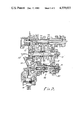
- FIG. 2 is a cross-sectional elevation of a transmission employing a torque damper of the present invention.
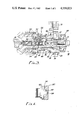
- FIG. 3 is a cross-sectional elevation illustrating the torque damper of the present invention in greater detail.
- FIG. 4 is a cross-sectional view taken along line IV--IV of FIG. 3.
- the torque damper includes a cam coupling mechanism including a cam follower b and a cam c.
- the cam c has a radially extending surface upon which the cam follower b rides.
- the cam c is part of a drive member d which is mounted on the driven shaft a by splines such that the member d may move axially relative to the shaft a but is constrained from rotating relative to the shaft.
- a piston e is associated with the drive member d to stroke within a sleeve f fixed relative to the drive shaft a.
- An orifice g permits flow from the two oil chambers h and i for damping purposes.
- a spring j biases the drive member d toward the cam follower b.
- a case 10 is illustrated within which a transmission mechanism is located.
- the mechanism includes a countershaft 12 and a driven shaft 14.
- a final output shaft 16 directs power from the mechanism.
- a gear wheel 18 meshes with a driven gear wheel 20.
- the driven gear wheel 20 is mounted such that it may rotate relative to the driven shaft.
- Lubricant flow is illustrated by a plurality of arrows in FIG. 2. Communication is shown to exist between the lubricant source 22 and the driven shaft 14 through a lubricant passage 24 extending to a concentric location in the shaft 14 to feed the torque damper, generally designated 26.
- the driven shaft 14 is shown to be rotatably mounted within bearings 28 and 30.
- a first drive member 32 is concentrically mounted about the driven shaft 14.
- Axial splines 34 constrain the first drive member to rotate with the driven shaft 14 but allow relative axial movement therebetween.
- Extending from one end of the first driven member 32 is a cam follower 36.
- the driven gear wheel 20 cooperates with the cam follower 36 by providing a cam 38 having radially extending cam surfaces 40 to which the cam followers 36 extend. This relationship is best illustrated in FIG. 4. As can also be seen in FIG.
- a sleeve 44 Spaced from the cam coupling mechanism and fixed to the driven shaft 14 is a sleeve 44.
- the sleeve 44 is concentrically mounted to the driven shaft 14 and extends axially to define an annular cavity between the sleeve 44 and the periphery of the driven shaft 14. Extending into the cavity thus formed is an annular piston 46.
- the annular piston 46 is integral with the first drive member 32 which is able to move axially relative to the driven shaft 14 and in turn the sleeve 44.
- a variable volume chamber 48 is formed within the sleeve 44 and is closed by the piston 46.
- the first drive member 32 is caused to move axially back and forth on the driven shaft 14 according to the torque load imposed on the drive train. This is a result of cooperation between the cam 38 and cam follower 36 of the cam coupling mechanism.
- the piston 46 moves axially relative to the driven shaft 14 so as to increase and reduce the variable volume 48.
- the piston advances to reduce the volume of the chamber 48.
- the volume is increased.
- the motion of the piston 46 drives oil contained within the chamber 48 through passageways 50 into and from the interior of the driven shaft 14.
- a spring 52 extends between a flange 54 on the sleeve 44 and a shoulder 56 on the first drive member 32. The spring 52 is maintained in compression to bias the first drive member 32 toward the gear wheel 20.
- a passage 58 Located concentrically within the driven shaft 14 is a passage 58.
- the passage 58 is in communication at a first end with the lubricant supply passage 24.
- the passageways 50 are also in communication with the central passage 58.
- Positioned within the passage 58 is a valve sleeve 60.
- the valve sleeve 60 provides a seat for a check valve 62.
- the check valve 62 operates in a conventional manner to allow flow in one direction, toward the right in FIG. 3, and prevent flow in the other direction.
- a bias spring 64 retains the check valve 62 in the seated condition except when relative pressure promotes flow therethrough.
- the check valve 62 is located between the source of lubricant and the passageways 50 in communication with the variable volume chamber 48.
- the passage 58 extends beyond the point of communication with the passageways 50 to form further internal volume.
- a flow restricter 66 defined by a thin plate with a hole therethrough divides the internal volume of the passage 58. This flow restricter 66 is held in place by means of a bias spring 68 against a shoulder 70 formed in the passage 58.
- the two internal bias springs 64 and 68 are maintained in position by means of a spring keeper 72.
- the flow restricter 66 and the check valve 62 are on opposite sides of the point of communication with the surrounding annular variable volume chamber 48.
- an accumulator piston 74 On the opposite side of the flow restricter from the check valve 62 is an accumulator piston 74.
- the accumulator piston 74 is biased toward the passage 58 by means of a spring 76 to reduce the volume of the passage 58.
- the variable volume chamber 48 is compressed, the increased fluid volume directed into the passage 58 is accommodated by the accumulater piston 74.
- variable volume chamber 48 is located radially outwardly of the damping mechanism itself. In this way, axial length of the unit is substantially reduced.
- the elements of the damping system are shown to be concentrically mounted within the rotating driven shaft 14. In this way, centrifugal force does not affect the components such as the check valve 62 or the orifice plate of the flow restricter 66.
- the piston 46 when torque is released from the drive train, the piston 46 will retract. This creates a reduced pressure in the damping system.
- the flow restricter include an orifice plate which is biased against the shoulder 70, the orifice plate may move quickly to the left, as seen in FIG. 3, so as to accommodate that release of torque. As a result, there is no tendency for air to be drawn into the damping system.
Landscapes
- Engineering & Computer Science (AREA)
- General Engineering & Computer Science (AREA)
- Mechanical Engineering (AREA)
- Shafts, Cranks, Connecting Bars, And Related Bearings (AREA)
- Valve Device For Special Equipments (AREA)
Applications Claiming Priority (2)
| Application Number | Priority Date | Filing Date | Title |
|---|---|---|---|
| JP58-47178 | 1983-03-23 | ||
| JP58047178A JPS59175623A (ja) | 1983-03-23 | 1983-03-23 | トルクダンパ装置 |
Publications (1)
| Publication Number | Publication Date |
|---|---|
| US4559023A true US4559023A (en) | 1985-12-17 |
Family
ID=12767819
Family Applications (1)
| Application Number | Title | Priority Date | Filing Date |
|---|---|---|---|
| US06/592,601 Expired - Fee Related US4559023A (en) | 1983-03-23 | 1984-03-22 | Torque damper |
Country Status (2)
| Country | Link |
|---|---|
| US (1) | US4559023A (enExample) |
| JP (1) | JPS59175623A (enExample) |
Cited By (12)
| Publication number | Priority date | Publication date | Assignee | Title |
|---|---|---|---|---|
| US4765197A (en) * | 1984-07-02 | 1988-08-23 | Dana Corporation | Spacer for transmission shaft |
| US4990122A (en) * | 1987-12-21 | 1991-02-05 | Sundstrand Corporation | Shaft failure indicator |
| US5033323A (en) * | 1989-02-24 | 1991-07-23 | Eaton Corporation | Gear rattle damper for countershaft transmissions |
| DE4115243A1 (de) * | 1991-05-10 | 1992-11-12 | Bayerische Motoren Werke Ag | Drehschwingungsdaempfer fuer ein kraftfahrzeuggetriebe |
| EP0807768A1 (en) * | 1996-05-15 | 1997-11-19 | Hyundai Motor Company | A transfer shaft for an automatic transmission |
| US5855518A (en) * | 1995-07-17 | 1999-01-05 | Nsk Ltd. | Damper device for rotary motion |
| US20040051319A1 (en) * | 2002-09-12 | 2004-03-18 | Denso Corporation | Starter |
| US20110072924A1 (en) * | 2009-09-29 | 2011-03-31 | Hiroshi Sotani | Power unit for a vehicle |
| US20160076634A1 (en) * | 2014-09-16 | 2016-03-17 | Honda Motor Co., Ltd. | Vibration isolation structure of power unit including torque dampers |
| US20160305529A1 (en) * | 2015-04-17 | 2016-10-20 | E-Aam Driveline Systems Ab | Transmission with pinion for reduced backlash |
| AU2014200254B2 (en) * | 2013-03-28 | 2017-02-02 | Honda Motor Co., Ltd. | Vibration isolating structure for power unit |
| CN113557368A (zh) * | 2019-03-11 | 2021-10-26 | 采埃孚股份公司 | 用于将第一可旋转部件互锁地连接至第二可旋转部件的爪形联接件 |
Families Citing this family (1)
| Publication number | Priority date | Publication date | Assignee | Title |
|---|---|---|---|---|
| JP5227922B2 (ja) * | 2009-08-27 | 2013-07-03 | 本田技研工業株式会社 | 鞍乗り型車両のトルクダンパ装置 |
Citations (4)
| Publication number | Priority date | Publication date | Assignee | Title |
|---|---|---|---|---|
| US2546633A (en) * | 1946-02-08 | 1951-03-27 | Adiel Y Dodge | Speed and torque responsive coupling |
| US2644439A (en) * | 1948-12-27 | 1953-07-07 | Bayerische Motoren Werke Ag | Change speed and starting gearing for motorcycles |
| US2683512A (en) * | 1949-11-09 | 1954-07-13 | Reed Roller Bit Co | Clutch |
| US4272973A (en) * | 1979-04-26 | 1981-06-16 | Fu Tsai Lee | Socket joint for torque wrench |
Family Cites Families (1)
| Publication number | Priority date | Publication date | Assignee | Title |
|---|---|---|---|---|
| JPS5527503A (en) * | 1978-08-12 | 1980-02-27 | Honda Motor Co Ltd | Torsional vibration attenuating mechanism for use in speed change gear |
-
1983
- 1983-03-23 JP JP58047178A patent/JPS59175623A/ja active Granted
-
1984
- 1984-03-22 US US06/592,601 patent/US4559023A/en not_active Expired - Fee Related
Patent Citations (4)
| Publication number | Priority date | Publication date | Assignee | Title |
|---|---|---|---|---|
| US2546633A (en) * | 1946-02-08 | 1951-03-27 | Adiel Y Dodge | Speed and torque responsive coupling |
| US2644439A (en) * | 1948-12-27 | 1953-07-07 | Bayerische Motoren Werke Ag | Change speed and starting gearing for motorcycles |
| US2683512A (en) * | 1949-11-09 | 1954-07-13 | Reed Roller Bit Co | Clutch |
| US4272973A (en) * | 1979-04-26 | 1981-06-16 | Fu Tsai Lee | Socket joint for torque wrench |
Cited By (16)
| Publication number | Priority date | Publication date | Assignee | Title |
|---|---|---|---|---|
| US4765197A (en) * | 1984-07-02 | 1988-08-23 | Dana Corporation | Spacer for transmission shaft |
| US4990122A (en) * | 1987-12-21 | 1991-02-05 | Sundstrand Corporation | Shaft failure indicator |
| US5033323A (en) * | 1989-02-24 | 1991-07-23 | Eaton Corporation | Gear rattle damper for countershaft transmissions |
| DE4115243A1 (de) * | 1991-05-10 | 1992-11-12 | Bayerische Motoren Werke Ag | Drehschwingungsdaempfer fuer ein kraftfahrzeuggetriebe |
| US5855518A (en) * | 1995-07-17 | 1999-01-05 | Nsk Ltd. | Damper device for rotary motion |
| EP0807768A1 (en) * | 1996-05-15 | 1997-11-19 | Hyundai Motor Company | A transfer shaft for an automatic transmission |
| US20040051319A1 (en) * | 2002-09-12 | 2004-03-18 | Denso Corporation | Starter |
| US8943918B2 (en) * | 2009-09-29 | 2015-02-03 | Honda Motor Co., Ltd. | Power unit for a vehicle |
| US20110072924A1 (en) * | 2009-09-29 | 2011-03-31 | Hiroshi Sotani | Power unit for a vehicle |
| AU2014200254B2 (en) * | 2013-03-28 | 2017-02-02 | Honda Motor Co., Ltd. | Vibration isolating structure for power unit |
| US20160076634A1 (en) * | 2014-09-16 | 2016-03-17 | Honda Motor Co., Ltd. | Vibration isolation structure of power unit including torque dampers |
| US10001204B2 (en) * | 2014-09-16 | 2018-06-19 | Honda Motor Co., Ltd. | Vibration isolation structure of power unit including torque dampers |
| US20160305529A1 (en) * | 2015-04-17 | 2016-10-20 | E-Aam Driveline Systems Ab | Transmission with pinion for reduced backlash |
| US9903460B2 (en) * | 2015-04-17 | 2018-02-27 | E-Aam Driveline Systems Ab | Transmission with pinion for reduced backlash |
| CN113557368A (zh) * | 2019-03-11 | 2021-10-26 | 采埃孚股份公司 | 用于将第一可旋转部件互锁地连接至第二可旋转部件的爪形联接件 |
| CN113557368B (zh) * | 2019-03-11 | 2024-02-23 | 采埃孚股份公司 | 用于将第一可旋转部件互锁地连接至第二可旋转部件的爪形联接件 |
Also Published As
| Publication number | Publication date |
|---|---|
| JPS59175623A (ja) | 1984-10-04 |
| JPH0218447B2 (enExample) | 1990-04-25 |
Similar Documents
| Publication | Publication Date | Title |
|---|---|---|
| US4559023A (en) | Torque damper | |
| US6622839B2 (en) | Multiple clutch arrangement | |
| US5855518A (en) | Damper device for rotary motion | |
| US4561827A (en) | Air compressor having condition responsive clutch control | |
| US3902567A (en) | Noise attenuating transmission casing | |
| US7147092B2 (en) | Multiple clutch unit | |
| US11976694B2 (en) | Power take off including a torsional vibration damping assembly | |
| KR0152373B1 (ko) | 캠축 위상조정 구동부 | |
| JPH0341246A (ja) | チエーン伝動装置またはベルト伝動装置に用いられる緊張装置 | |
| EP2153085B1 (de) | Torsionsschwingungsdämpfersystem für den antriebsstrang eines fahrzeugs | |
| US2418901A (en) | Crosshead and guide structure | |
| US3603112A (en) | Injection pump for internal combustion engines | |
| US2400119A (en) | Variable displacement pump | |
| US3421343A (en) | Engine drive system | |
| US6324843B1 (en) | Hydraulic-mechanical type continuously variable transmission for vehicle | |
| US20190031024A1 (en) | Viscous coupling and power take off assembly for a drive train system | |
| DE3874542T2 (de) | Luefterkupplung. | |
| US4708231A (en) | Centrifugal clutch | |
| US5385018A (en) | Device for transmitting automotive engine driving torque for automatic power transmission with feature of absorption of torsional vibration | |
| US5017178A (en) | Resilient coupling apparatus | |
| US4924728A (en) | Gear shift mechanism with a damper device | |
| US2293731A (en) | Hydraulic clutch transmission mechanism | |
| DE102009027219B4 (de) | Torsionsschwingungsdämpferanordnung | |
| US6561305B2 (en) | Hydraulic clutching steering damper | |
| EP0221064A1 (en) | Shock absorber |
Legal Events
| Date | Code | Title | Description |
|---|---|---|---|
| AS | Assignment |
Owner name: HONDA GIKEN KOGYO KABUSHIKI KAISHA NO. 27-8, 6-CHO Free format text: ASSIGNMENT OF ASSIGNORS INTEREST.;ASSIGNORS:UCHIBABA, KOUICHI;HAYASHI, TSUTOMU;ISHIKAWA, HARUO;AND OTHERS;REEL/FRAME:004301/0794 Effective date: 19840615 |
|
| FEPP | Fee payment procedure |
Free format text: PAYOR NUMBER ASSIGNED (ORIGINAL EVENT CODE: ASPN); ENTITY STATUS OF PATENT OWNER: LARGE ENTITY |
|
| FPAY | Fee payment |
Year of fee payment: 4 |
|
| REMI | Maintenance fee reminder mailed | ||
| LAPS | Lapse for failure to pay maintenance fees | ||
| FP | Lapsed due to failure to pay maintenance fee |
Effective date: 19931219 |
|
| STCH | Information on status: patent discontinuation |
Free format text: PATENT EXPIRED DUE TO NONPAYMENT OF MAINTENANCE FEES UNDER 37 CFR 1.362 |