US4545007A - Luminaire with lenticular lens - Google Patents
Luminaire with lenticular lens Download PDFInfo
- Publication number
- US4545007A US4545007A US06/649,576 US64957684A US4545007A US 4545007 A US4545007 A US 4545007A US 64957684 A US64957684 A US 64957684A US 4545007 A US4545007 A US 4545007A
- Authority
- US
- United States
- Prior art keywords
- light
- lenticular lens
- lens
- luminaire
- lentical
- Prior art date
- Legal status (The legal status is an assumption and is not a legal conclusion. Google has not performed a legal analysis and makes no representation as to the accuracy of the status listed.)
- Expired - Lifetime
Links
Images


Classifications
-
- F—MECHANICAL ENGINEERING; LIGHTING; HEATING; WEAPONS; BLASTING
- F21—LIGHTING
- F21V—FUNCTIONAL FEATURES OR DETAILS OF LIGHTING DEVICES OR SYSTEMS THEREOF; STRUCTURAL COMBINATIONS OF LIGHTING DEVICES WITH OTHER ARTICLES, NOT OTHERWISE PROVIDED FOR
- F21V5/00—Refractors for light sources
- F21V5/04—Refractors for light sources of lens shape
- F21V5/048—Refractors for light sources of lens shape the lens being a simple lens adapted to cooperate with a point-like source for emitting mainly in one direction and having an axis coincident with the main light transmission direction, e.g. convergent or divergent lenses, plano-concave or plano-convex lenses
Definitions
- This invention relates to luminaire lighting, and more particularly, a lenticular lens for high intensity flood or area lighting with precise beam control.
- the design of luminaires for high intensity lighting presents certain difficult problems in obtaining good luminance without undesirable bright spots.
- luminaires for flood or area lighting use shaped specular reflectors which redirect incident light flux from an intense light source to form a desired beam.
- Conventional reflector shapes are parabolic, for a narrow beam; elliptical, hyperbolic and spherical, for a wide beam; or a combination of sections of the four shapes.
- the function of the reflector is to distribute the light both functionally and efficiently.
- the difficulty is that an observer sees two segments of light: the source itself and a reflected image of the light source.
- these segments represent only a small fraction of the total luminaire face, they produce high source brightness or direct glare. While this can be minimized by the use of diffusion devices, such as frosting or pebbling, this often results in loss of beam control. Also, such anti-glare devices tend to spread the light beyond desired beam angles thereby reducing the efficiency of the luminaire.
- the present invention is intended to overcome the foregoing difficulties in a high intensity luminaire for flood or area lumination.
- the present invention is particularly suited for use with high intensity light sources such as the so-called halogen light sources.
- a lenticular lens for distributing the high intensity light flux over the entire face of the luminaire.
- the luminaire itself comprises a parabolic reflector with the light source positioned at or near its focus. Incident light flux is reflected in a parallel direction by the reflector through the lenticular lens.
- the lens itself refracts parallel rays reflected from the reflector by means of aspheric curved surfaces on each lens element, or lentical, to a focal point directly in front of the lentical. Since each lentical distributes the light rays only in a predetermined cone, maximum efficiency is obtained. The observer sees a multiple of tiny light images of the light source with a dark surround.
- the lenticular lens functions as if the luminaire had as many light sources as there are lenticals. If, for example, a lenticular lens contains 2,000 identical lenticules, the light passing through the lens forms 2,000 separate images. Each image is 1/2,000ths of the total flux of the fixture. When viewed from any normal viewing angle, the lens appears to have a multitude of tiny light images, each with a dark surround. The result is a minimum brightness from any viewing angle. Each lentical independently produces a complete distribution of light and the amount of light distributed by each lentical has the same pattern as every other lentical.
- the lenticular lens comprises a plurality of continuous polygonal lens elements with each element comprising a highly polished aspherical curved entrance surface and a flat exit surface.
- the aspheric surface of each lentical is divided into a number of coaxial zones, each designed to accept a specific quantity of light flux from the parabolic reflector and refract that quantity of flux into a specific solid angle of the projected beam.
- desired distribution of light is achieved.
- the convergence of light rays by each lenticular lens element produces a real image of the light source in front of the lenticular lens and all images are substantially identical.
- the geometric light distribution from all images is also identical.
- a lenticular lens for a luminaire comprising a plurality of contiguous polygonal lens elements, each element having a light receiving end and a light transmitting end.
- the light receiving end of each element is substantially aspherical and is defined by a plurality of coaxial arcs of differing radii.
- the exit end of each lentical is substantially flat.
- Each lentical or lens element is preferably hexagonal so that they can be arranged in abutting relation to each other.
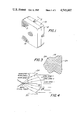
- FIG. 1 is a perspective of the luminaire of the present invention.
- FIG. 2 is a transverse sectional view of the luminaire shown in FIG. 1 taken along the line 2--2.
- FIG. 3 is a partial front view of the lenticular lens in accordance with the present invention.
- FIG. 4 is an enlarged, transverse sectional view of the lenticular lens showing one of the lenticals.
- FIG. 5 is an enlarged, transverse sectional view of one of the lenticals showing its basic dimensions.
- a luminaire 10 comprising a casing 12 with the lenticular lens 14 mounted in its front face.
- the luminaire 10 includes a parabolic reflector 16 held in position by a pair of brackets 18 and 20 fixed to the rear of casing 12 by threaded fasteners.
- the luminaire 10 is also provided with an appropriate socket (not shown) for supporting an alkaline metal type lamp such as high power sodium or mercury vapor at or near the focus of the reflector 16.
- an alkaline metal type lamp such as high power sodium or mercury vapor at or near the focus of the reflector 16.
- light flux emitted from the lamp 22 is reflected by the parabolic reflector 16 as parallel rays passing through the lenticular lens 14.
- the lens 14 is fixed in the front surface of a casing 12 by any conventional means.
- ballast and electrical connections for the lamp 22 are conventional, and play no part in the present invention, they have not been illustrated.
- the lenticular lens 14 comprises a plurality of lenticals 24 which are hexagonal in cross section.
- the hexagonal cross sectional shape is chosen so that each lentical is fully contiguous with every other lentical except of course those on the edge of the lens 14.
- the hexagonal cross sectional shape is preferred, other shapes may be chosen.
- Each lentical is identical to every other lentical.
- a typical lentical 24 is illustrated in FIG. 4.
- Each lentical 24 comprises an aspheric light entrance surface 28 and a flat light exit surface 30.
- Each light entrance surface is convex and comprises a set of highly polished aspherical curved surfaces divided into a number of coaxial zones. Each zone accepts a specific quantity of parallel light flux from the reflector 16 and refracts that flux into a specific solid angle of the projected beam.
- parallel light rays strike the lentical 24 and are refracted to form an image of the light source in front of the lenticular element. The image need not be sharply focused.
- the exemplary concave entrance surface 28 is divided into three co-axial zones labeled lens zone 1, lens zone 2 and lens zone 3. Each lens zone has a different radius of curvature but is coaxial with the lenses central axis of the lens 32.
- parallel flux entering lens zone 3 is refracted by the lentical 24 and exits at beam zone 3.
- Parallel light entering lens zone 2 is refracted and exits at beam zone 2.
- Parallel flux entering lens zone 1 is refracted and exits at beam zone 1.
- additional zones may be used as desired.
- the precise radius of curvature for each lens zone can be varied depending upon the desired angle of flux distribution.
- the entrance surface should be highly polished.
- FIG. 5 shows the dimensions of a lentical for a lenticular lens to be used as a flood light.
- the following is a table of the dimensions for a typical lentical for a lenticular lens used as a flood lamp in accordance with the present invention.
- the cross-over of light rays in front of the lenticular lens does not necessarily form a sharp image of the light source.
- the degree of sharpness of focus depends upon the light distribution desired.
- By controlling the shape of each zone on the entrance surface light is refracted into a desired beam zone.
- the angular spread of the beam zones combined with the quantity of flux in each zone determines final beam distribution of the lentical. Since all lenticals are identical and all light incident on the lenticular lens is substantially parallel, it follows that the beam spread characteristics from all elements are identical.
- Luminaires constructed with lenticular lenses made in accordance with the present invention have demonstrated excellent light distribution qualities.
- a flood luminaire with a 50 watt high pressure sodium lamp projects approximately 800 candelas at 35° horizontally.
- Observers viewing an 81/2" by 81/2" lenticular lens see 800 candelas spread throughout the entire projected face area of the luminaire.
- Photographic examinations show that each lentical appears to be an individual light source with a dark surround.
- a conventional flood light viewed at the same angle appears to project all 800 candelas from a small portion of the total projected face area.
- each lentical acts as a mini light source, and there are as many light sources distributed across the face of the lenticular lens as there are lenticals.
- Each of these light sources produces a complete distribution of light independently. If for example, the beam produced by the luminaire 10 is 127° horizontal by 127° vertical then each individual lens element also produces 127° by 127° beam, but in any given direction the candelas produced by one lentical is a fraction of the total candelas of the luminaire and conversely the candelas intensity of the luminaire in any direction is the total of all of the individual candelas from all of the lens elements in that direction.
- candelas intensity in any direction eminates from light sources spread throughout the total face area of the luminaire and therefore maximum surface brightness is always at the minimum possible, since candelas per square inch are always candelas divided by the full projected area of the lenticular lens.
- a conventional flood light using a specular reflector with a clear glass cover plate, having equal distribution, will project the 800 candelas at 35° horizontal from a small portion of the total projected face area.
Abstract
Description
______________________________________
            Radius Of
                    Distance
            Curvature
                    From Axis
______________________________________
Lens Zone 1   .078"       .0 to .039"
Lens Zone 2   .156"     .039" to .072"
Lens Zone 3   .250"     .072" to .115"
______________________________________
 Hexagonal cross sectional shape
 Vertical spacing  each lenticule
 Horizontal spacing  each lenticule .1732
Claims (7)
Priority Applications (2)
| Application Number | Priority Date | Filing Date | Title |
|---|---|---|---|
| US06/649,576 US4545007A (en) | 1984-09-12 | 1984-09-12 | Luminaire with lenticular lens |
| CA000488299A CA1244390A (en) | 1984-09-12 | 1985-08-08 | Luminaire with lenticular lens |
Applications Claiming Priority (1)
| Application Number | Priority Date | Filing Date | Title |
|---|---|---|---|
| US06/649,576 US4545007A (en) | 1984-09-12 | 1984-09-12 | Luminaire with lenticular lens |
Publications (1)
| Publication Number | Publication Date |
|---|---|
| US4545007A true US4545007A (en) | 1985-10-01 |
Family
ID=24605401
Family Applications (1)
| Application Number | Title | Priority Date | Filing Date |
|---|---|---|---|
| US06/649,576 Expired - Lifetime US4545007A (en) | 1984-09-12 | 1984-09-12 | Luminaire with lenticular lens |
Country Status (2)
| Country | Link |
|---|---|
| US (1) | US4545007A (en) |
| CA (1) | CA1244390A (en) |
Cited By (13)
| Publication number | Priority date | Publication date | Assignee | Title |
|---|---|---|---|---|
| US4722023A (en) * | 1984-05-15 | 1988-01-26 | Koito Seisakusho Co., Ltd. | Lamp assembly for emitting a beam of light at an angle to its optical axis |
| EP0389724A1 (en) * | 1989-03-27 | 1990-10-03 | Bachir Hihi | Light-source multiplication device |
| US4991073A (en) * | 1989-03-08 | 1991-02-05 | Gte Products Corporation | Lighting lens |
| US5043856A (en) * | 1989-03-08 | 1991-08-27 | Gte Products Corporation | Lighting lens |
| WO1992000487A1 (en) * | 1990-06-23 | 1992-01-09 | Robert Bosch Gmbh | Vehicle headlight |
| US5168646A (en) * | 1990-06-01 | 1992-12-08 | Ncm International, Inc. | Visual effect graphic and method of making same |
| EP0598546A1 (en) * | 1992-11-16 | 1994-05-25 | General Electric Company | Lenticular lenses |
| US5442252A (en) * | 1992-11-16 | 1995-08-15 | General Electric Company | Lenticulated lens with improved light distribution |
| US5444606A (en) * | 1994-02-10 | 1995-08-22 | Lexalite International Corporation | Prismatic reflector and prismatic lens |
| USD377994S (en) * | 1995-07-24 | 1997-02-11 | Morrill Cindy M | Protective cover for use with a magnifying lamp |
| US6102558A (en) * | 1997-05-23 | 2000-08-15 | Valeo Vision | Motor vehicle headlight with a reflector for generating a wide beam, and with a striated cover lens |
| US6550942B1 (en) * | 1998-04-16 | 2003-04-22 | Alliedsignal Inc. | Linear illumination sources and systems |
| US20060002112A1 (en) * | 2004-07-01 | 2006-01-05 | Osram Sylvania Inc. | Incandescent reflector heat lamp with uniform irradiance |
Citations (17)
| Publication number | Priority date | Publication date | Assignee | Title |
|---|---|---|---|---|
| US65817A (en) * | 1867-06-18 | Improvement in the construction of signs | ||
| US595273A (en) * | 1897-12-07 | soper | ||
| US1259492A (en) * | 1917-04-19 | 1918-03-19 | Holophane Glass Company Inc | Lantern-plate. |
| US1751984A (en) * | 1926-12-30 | 1930-03-25 | American Gasaccumulator Co | Reflector |
| US1969982A (en) * | 1931-03-12 | 1934-08-14 | John L Lehman | Light beam reflecting and controlling means |
| US2086182A (en) * | 1937-07-06 | Method of and apparatus fob pro | ||
| US2183249A (en) * | 1937-11-06 | 1939-12-12 | Zeiss Ikon Ag | Illuminating device for projectors |
| US2229693A (en) * | 1937-02-18 | 1941-01-28 | Max Hermann Wende | Antidazzle head lamp |
| DE956568C (en) * | 1958-11-21 | 1957-01-17 | Kurt Koerber & Co K G | Cigarette rod machine |
| CA555654A (en) * | 1958-04-08 | W. Onksen George | Vehicle lamp lens | |
| US2907249A (en) * | 1956-10-05 | 1959-10-06 | Electro Seal Corp | Lens for signal lights |
| US3222516A (en) * | 1963-06-24 | 1965-12-07 | Lancaster Glass Corp | Lenticulated lens for traffic light |
| US3267278A (en) * | 1965-02-24 | 1966-08-16 | Elastic Stop Nut Corp | Lens and lens assemblies |
| US3357770A (en) * | 1961-10-02 | 1967-12-12 | Intermountain Res And Engineer | Stereoscopic viewing apparatus which includes a curved lenticular screen in front ofa curved picture supporting surface |
| US3794829A (en) * | 1972-04-20 | 1974-02-26 | I Taltavull | Non-luminance lighting panel |
| DE2846842A1 (en) * | 1978-10-27 | 1980-04-30 | Albert Schmid | Multiple colour lighting equipment - has light source and translucent scatter disc with sections having different colours |
| US4471412A (en) * | 1982-01-09 | 1984-09-11 | Kei Mori | Illumination device |
-
1984
- 1984-09-12 US US06/649,576 patent/US4545007A/en not_active Expired - Lifetime
-
1985
- 1985-08-08 CA CA000488299A patent/CA1244390A/en not_active Expired
Patent Citations (17)
| Publication number | Priority date | Publication date | Assignee | Title |
|---|---|---|---|---|
| US595273A (en) * | 1897-12-07 | soper | ||
| US2086182A (en) * | 1937-07-06 | Method of and apparatus fob pro | ||
| US65817A (en) * | 1867-06-18 | Improvement in the construction of signs | ||
| CA555654A (en) * | 1958-04-08 | W. Onksen George | Vehicle lamp lens | |
| US1259492A (en) * | 1917-04-19 | 1918-03-19 | Holophane Glass Company Inc | Lantern-plate. |
| US1751984A (en) * | 1926-12-30 | 1930-03-25 | American Gasaccumulator Co | Reflector |
| US1969982A (en) * | 1931-03-12 | 1934-08-14 | John L Lehman | Light beam reflecting and controlling means |
| US2229693A (en) * | 1937-02-18 | 1941-01-28 | Max Hermann Wende | Antidazzle head lamp |
| US2183249A (en) * | 1937-11-06 | 1939-12-12 | Zeiss Ikon Ag | Illuminating device for projectors |
| US2907249A (en) * | 1956-10-05 | 1959-10-06 | Electro Seal Corp | Lens for signal lights |
| DE956568C (en) * | 1958-11-21 | 1957-01-17 | Kurt Koerber & Co K G | Cigarette rod machine |
| US3357770A (en) * | 1961-10-02 | 1967-12-12 | Intermountain Res And Engineer | Stereoscopic viewing apparatus which includes a curved lenticular screen in front ofa curved picture supporting surface |
| US3222516A (en) * | 1963-06-24 | 1965-12-07 | Lancaster Glass Corp | Lenticulated lens for traffic light |
| US3267278A (en) * | 1965-02-24 | 1966-08-16 | Elastic Stop Nut Corp | Lens and lens assemblies |
| US3794829A (en) * | 1972-04-20 | 1974-02-26 | I Taltavull | Non-luminance lighting panel |
| DE2846842A1 (en) * | 1978-10-27 | 1980-04-30 | Albert Schmid | Multiple colour lighting equipment - has light source and translucent scatter disc with sections having different colours |
| US4471412A (en) * | 1982-01-09 | 1984-09-11 | Kei Mori | Illumination device |
Cited By (17)
| Publication number | Priority date | Publication date | Assignee | Title |
|---|---|---|---|---|
| US4722023A (en) * | 1984-05-15 | 1988-01-26 | Koito Seisakusho Co., Ltd. | Lamp assembly for emitting a beam of light at an angle to its optical axis |
| US4991073A (en) * | 1989-03-08 | 1991-02-05 | Gte Products Corporation | Lighting lens |
| US5043856A (en) * | 1989-03-08 | 1991-08-27 | Gte Products Corporation | Lighting lens |
| EP0389724A1 (en) * | 1989-03-27 | 1990-10-03 | Bachir Hihi | Light-source multiplication device |
| US5168646A (en) * | 1990-06-01 | 1992-12-08 | Ncm International, Inc. | Visual effect graphic and method of making same |
| WO1992000487A1 (en) * | 1990-06-23 | 1992-01-09 | Robert Bosch Gmbh | Vehicle headlight |
| US5307246A (en) * | 1990-06-23 | 1994-04-26 | Robert Bosch Gmbh | Vehicle lamp |
| US5442252A (en) * | 1992-11-16 | 1995-08-15 | General Electric Company | Lenticulated lens with improved light distribution |
| EP0598546A1 (en) * | 1992-11-16 | 1994-05-25 | General Electric Company | Lenticular lenses |
| US5683175A (en) * | 1992-11-16 | 1997-11-04 | General Electric Company | Lenticulated lens |
| US5444606A (en) * | 1994-02-10 | 1995-08-22 | Lexalite International Corporation | Prismatic reflector and prismatic lens |
| USD377994S (en) * | 1995-07-24 | 1997-02-11 | Morrill Cindy M | Protective cover for use with a magnifying lamp |
| US6102558A (en) * | 1997-05-23 | 2000-08-15 | Valeo Vision | Motor vehicle headlight with a reflector for generating a wide beam, and with a striated cover lens |
| US6550942B1 (en) * | 1998-04-16 | 2003-04-22 | Alliedsignal Inc. | Linear illumination sources and systems |
| US20060002112A1 (en) * | 2004-07-01 | 2006-01-05 | Osram Sylvania Inc. | Incandescent reflector heat lamp with uniform irradiance |
| US7196460B2 (en) * | 2004-07-01 | 2007-03-27 | Osram Sylvania Inc. | Incandescent reflector heat lamp with uniform irradiance |
| GB2415771B (en) * | 2004-07-01 | 2009-04-22 | Osram Sylvania Inc | Incandescent reflector heat lamp with uniform irradiance |
Also Published As
| Publication number | Publication date |
|---|---|
| CA1244390A (en) | 1988-11-08 |
Similar Documents
| Publication | Publication Date | Title |
|---|---|---|
| US5897201A (en) | Architectural lighting distributed from contained radially collimated light | |
| US3020395A (en) | Lighting device | |
| US5808759A (en) | Projection type display including a holographic diffuser | |
| JP2723251B2 (en) | Optical equipment that outputs normalized light | |
| US2002376A (en) | Searchlight reflector | |
| US7244050B2 (en) | Full cutoff area light fixture | |
| US4545007A (en) | Luminaire with lenticular lens | |
| JP2002525791A (en) | Lighting equipment | |
| EP2728246A1 (en) | Polyhedral secondary optical lens | |
| RU2293250C2 (en) | Searchlight with fresnel lens | |
| US5051878A (en) | Luminaire having a lensed reflector system for improved light distribution control | |
| US20110170291A1 (en) | Efficient and uniformly distributed illumination from multiple source luminairies | |
| JP2004046071A (en) | Light-beam directional optical structure | |
| CZ278791B6 (en) | Lighting system for lamps, projection and enlarging apparatus | |
| US5149191A (en) | Combination louver/lens light fixture shield | |
| US4698734A (en) | Lensed indirect luminaire with side angle brightness control | |
| GB2421584A (en) | Optical device with converging and diverging elements for directing light | |
| JPH10509809A (en) | Projector having a plurality of lamp light sources | |
| EP0071230B1 (en) | Lighting apparatus | |
| WO2009138228A1 (en) | Illumination apparatus | |
| AU677410B2 (en) | Luminaire | |
| US3950638A (en) | High intensity indirect lighting fixture | |
| US5235499A (en) | Lamp system having a torroidal light emitting member | |
| EP0509679A2 (en) | Vehicle Lamp | |
| US3786248A (en) | Luminaire |
Legal Events
| Date | Code | Title | Description |
|---|---|---|---|
| AS | Assignment |
Owner name: DEVINE LIGHTING, 4645 EAST 11TH ST., P.O. BOX 4324 Free format text: ASSIGNMENT OF ASSIGNORS INTEREST.;ASSIGNOR:NAGEL, ROBERT;REEL/FRAME:004315/0067 Effective date: 19840820 Owner name: DEVINE LIGHTING,MISSOURI Free format text: ASSIGNMENT OF ASSIGNORS INTEREST;ASSIGNOR:NAGEL, ROBERT;REEL/FRAME:004315/0067 Effective date: 19840820 |
|
| STCF | Information on status: patent grant |
Free format text: PATENTED CASE |
|
| FEPP | Fee payment procedure |
Free format text: PAYOR NUMBER ASSIGNED (ORIGINAL EVENT CODE: ASPN); ENTITY STATUS OF PATENT OWNER: SMALL ENTITY |
|
| FPAY | Fee payment |
Year of fee payment: 4 |
|
| FEPP | Fee payment procedure |
Free format text: PAT HOLDER CLAIMS SMALL ENTITY STATUS - SMALL BUSINESS (ORIGINAL EVENT CODE: SM02); ENTITY STATUS OF PATENT OWNER: SMALL ENTITY Free format text: PAYER NUMBER DE-ASSIGNED (ORIGINAL EVENT CODE: RMPN); ENTITY STATUS OF PATENT OWNER: SMALL ENTITY |
|
| FPAY | Fee payment |
Year of fee payment: 8 |
|
| REMI | Maintenance fee reminder mailed | ||
| FPAY | Fee payment |
Year of fee payment: 12 |
|
| SULP | Surcharge for late payment | ||
| AS | Assignment |
Owner name: HUBBELL LIGHTING, INC., CONNECTICUT Free format text: ASSIGNMENT OF ASSIGNORS INTEREST;ASSIGNOR:DEVINE LIGHTING, INC.;REEL/FRAME:009314/0425 Effective date: 19980707 |